Allen-Bradley Kinetix 5500 Installation Instructions Manual
Kinetix series 5500 servo drives
Hide thumbs
Also See for Kinetix 5500:
- User manual (278 pages) ,
- Design manual (118 pages) ,
- Installation instructions (2 pages)
Table of Contents
Advertisement
Installation Instructions
Kinetix 5500 Servo Drives
Catalog Numbers 2198-H003-ERS, 2198-H008-ERS, 2198-H015-ERS, 2198-H025-ERS,
2198-H040-ERS, 2198-H070-ERS, 2198-H003-ERS2, 2198-H008-ERS2, 2198-H015-ERS2,
2198-H025-ERS2, 2198-H040-ERS2, 2198-H070-ERS2
Topic
About the Kinetix 5500 Drives
About the Kinetix 5500 Drives
Kinetix® 5500 servo drives provide an Integrated Motion over the EtherNet/IP network solution
for applications with output power and current requirements in the range of 0.2...14.6 kW and
1.4...32.5 A 0-pk, respectively.
information on wiring, applying power, troubleshooting, and integration with ControlLogix®
EtherNet/IP network modules or CompactLogix™ 5370 controllers.
Page
1
2
3
3
4
5
9
12
15
18
19
Advertisement
Table of Contents

Related Manuals for Allen-Bradley Kinetix 5500


Summary of Contents for Allen-Bradley Kinetix 5500
-
Page 1: Table Of Contents
0.2…14.6 kW and 1.4…32.5 A 0-pk, respectively. Refer to the Kinetix 5500 Servo Drives User Manual, publication 2198-UM001, for detailed information on wiring, applying power, troubleshooting, and integration with ControlLogix®... -
Page 2: Important User Information
2 Kinetix 5500 Servo Drives Important User Information Read this document and the documents listed in the additional resources section about installation, configuration, and operation of this equipment before you install, configure, operate, or maintain this product. Users are required to familiarize themselves with installation and wiring instructions in addition to requirements of all applicable codes, laws, and standards. -
Page 3: Catalog Number Explanation
Kinetix 5500 Servo Drives 3 Catalog Number Explanation This publication applies to the following Kinetix 5500 servo drives. For connecting safe torque-off signals, hard-wired drives use the safe torque-off (STO) connector and ship with the protective cover removed. Networked safe torque-off drives do not use the STO connector and ship with the protective cover in place. -
Page 4: Removing The Grounding Screws In Ungrounded Power Configurations
If you have grounded wye power distribution, you do not need to remove the screws. Go to IMPORTANT Install the Kinetix 5500 Servo Drive on page Removing the ground screws can affect EMC performance. Removing the grounding screws in multi-axis configurations is best done when the drive is removed from the panel and placed on its side on a solid surface equipped as a grounded static-safe workstation. -
Page 5: Install The Kinetix 5500 Servo Drive
• AC fed ungrounded • Reduced leakage current (1) Refer to the Kinetix 5500 Servo Drives User Manual, publication 2198-UM001, for example configurations. Install the Kinetix 5500 Servo Drive These procedures assume you have prepared your panel and understand how to bond your system. - Page 6 Zero-stack Tab and Cutout Aligned 2. Mount the Kinetix 5500 drive to the cabinet subpanel with M4 (#8-32) steel machine screws torqued to 2.0 N•m (17.7 lb•in), max. Rockwell Automation Publication 2198-IN001C-EN-P - January 2014...
-
Page 7: Product Dimensions
Kinetix 5500 Servo Drives 7 Product Dimensions Included in this figure are the drill hole patterns for standalone drives. Refer to the Kinetix 5500 Servo Drives User Manual, publication 2198-UM001, for multi-axis drill-hole patterns. Kinetix 5500 Drives with 2198-KITCON-DSL Connector Kit Dimensions are in mm (in.) - Page 8 8 Kinetix 5500 Servo Drives Kinetix 5500 Drives with 2198-H2DCK Converter Kit Dimensions are in mm (in.) Frame 1 Servo Drive 2198-H2DCK Feedback Converter Kit Mounted on Frame 1 Drive 45.0 (1.77) 56.0 (2.20) (10.08) 2198-H2DCK 2198-H2DCK Feedback Converter Kit...
-
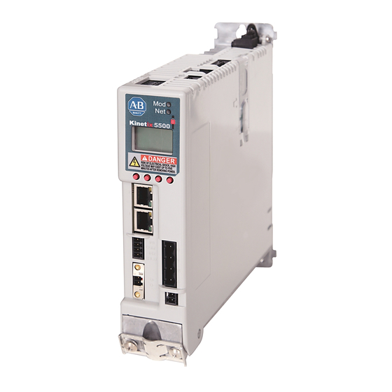
Page 9: Connector Data
Kinetix 5500 Servo Drives 9 Connector Data Use this illustration to identify the Kinetix 5500 drive features and indicators. Kinetix 5500 Drive Features and Indicators – Kinetix 5500 Drive, Top View Kinetix 5500 Drive, Front View (2198-H003-ERS2 drive is shown) - Page 10 10 Kinetix 5500 Servo Drives Kinetix 5500 Drive Connectors Designator Description Connector AC mains input power 4-position plug, terminal screws DC common bus power 2-position (T-connector used in shared-bus configurations) 24V control input power 2-position plug, terminal screws Shunt power...
- Page 11 2198-KITCON-DSL connector kit) termination point SHIELD SHIELD Cable shield and shield clamp (internal to 2198-H2DCK converter kit) termination point (1) Refer to Kinetix 5500 Servo Drives User Manual, publication 2198-UM001, for installation instructions. Motor Brake (BC) Connector Pinout BC Pin Description Signal...
-
Page 12: Wiring Requirements
-ERS drives ship with the safe torque-off function enabled. Connect the safe torque-off inputs to a safety circuit or install bypass wiring to enable motion. Refer to the Kinetix 5500 Servo Drives User Manual, publication 2198-UM001, for more information. Ethernet Communication PORT1 and PORT2 Pinout... - Page 13 Kinetix 5500 Servo Drives 13 Kinetix 5500 Drive Power and I/O Wiring Requirements Connects to Terminals Wire Size Strip Length Torque Value Kinetix 5500 Drive Description Cat. No. (AWG) mm (in.) N•m (lb•in) Signal 2198-H003-ERSx 2198-H008-ERSx 1.5…4 IPD-1 2198-H015-ERSx 8.0 (0.31) (16…12)
- Page 14 • Ground shielded power cables to prevent potentially high voltages on the shield. Ground Your Kinetix 5500 Drive to the Subpanel Ground Kinetix 5500 drives and 2198-CAPMOD-1300 capacitor modules to a bonded cabinet ground bus with a braided ground strap or 4.0 mm (12 AWG) copper wire.
-
Page 15: Attach The Motor Cable Shield Clamp
Kinetix 5500 Servo Drives 15 Attach the Motor Cable Shield Clamp A shield clamp and two screws are supplied with each Kinetix 5500 drive. Use the clamp to bond the motor cable shield-braid to chassis ground. • Routing the conductors with service loops provides stress relief. - Page 16 16 Kinetix 5500 Servo Drives 14 and 10 AWG Cable Installation Kinetix 5500 Servo Drives, Frame 2 or 3, Front View Motor Power (frame 2 is shown) (MP) Connector 2198-KITCON-DSL Clamp features apply Motor Feedback to all frame sizes. Motor Brake...
-
Page 17: Refer To The Kinetix 5500 Servo Drives User Manual, Publication 2198-Um001, For Detailed
2.0 N•m (17.7 lb•in.) cable diameter is smaller than the drive clamp alone. Refer to the Kinetix 5500 Servo Drives User Manual, publication 2198-UM001, for detailed information on wiring the 2198-H2DCK feedback converter kit and attaching the motor power/brake shield clamp. -
Page 18: Motor Overload Protection
18 Kinetix 5500 Servo Drives Motor Overload Protection This servo drive uses solid-state motor overload protection that operates in accordance with UL 508C. Motor overload protection is provided by algorithms (thermal memory) that predict actual motor temperature based on operating conditions as long as control power is continuously applied. -
Page 19: Additional Resources
Provides declarations of conformity, certificates, and other Product Certifications website, http://www.ab.com certification details. You can view or download publications at http://www.rockwellautomation.com/literature. To order paper copies of technical documentation, contact your local Allen-Bradley distributor or Rockwell Automation sales representative. Rockwell Automation Publication 2198-IN001C-EN-P - January 2014... -
Page 20: Documentation Feedback
Your comments will help us serve your documentation needs better. If you have any suggestions on how to improve this document, complete this form, publication RA-DU002, available at http://www.rockwellautomation.com/literature/. Allen-Bradley, CompactLogix, ControlLogix, Kinetix, Rockwell Software, and Rockwell Automation are trademarks of Rockwell Automation, Inc.
Need help?
Do you have a question about the Kinetix 5500 and is the answer not in the manual?
Questions and answers