STIEBEL ELTRON DHE 18 AU Operation And Installation
Instantaneous water heater with full electronic control
Hide thumbs
Also See for DHE 18 AU:
- Operation and installation (24 pages) ,
- Operation and installation manual (24 pages)

Related Manuals for STIEBEL ELTRON DHE 18 AU


Summary of Contents for STIEBEL ELTRON DHE 18 AU
- Page 1 OPERATION AND INSTALLATION Instantaneous water heater with full electronic control » DHE 18 AU » DHE 27 AU...
-
Page 2: Table Of Contents
CONTENTS | SPECIAL INFORMATION SPECIAL INFORMATION SPECIAL INFORMATION OPERATION General information �����������������������������������������3 - The appliance may be used by children aged 8 Safety instructions ����������������������������������������������� 3 and up and persons with reduced physical, sen- Other symbols in this documentation ����������������������� 3 sory or mental capabilities or a lack of experience Units of measurement ������������������������������������������... -
Page 3: General Information
OPERATION General information OPERATION Other symbols in this documentation Note Notes are bordered by horizontal lines above and below the text. General information is identified by the symbol General information shown on the left. f Read these texts carefully. The chapter "Operation" is intended for appliance users and qual- ified contractors. -
Page 4: Ce Designation
OPERATION Appliance description Where children or persons with limited physical, sensory or men- - when the output is less than 80 % tal abilities are allowed to use this appliance, we recommend a - when the maximum output is less than 80 % while the inlet permanent temperature limit. -
Page 5: Settings And Displays
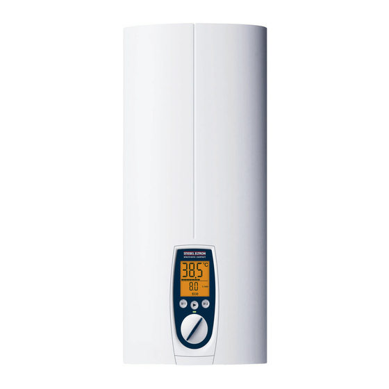
OPERATION Settings and displays Settings and displays Setting the temperature User interface 1 Temperature setting 20 - 60 °C in steps of 0.5 °C, OFF = heating system switched off 2 Programmed temperature selection 3 Economy monitor selection You can store a preferred temperature with memory key M. f Select a preferred temperature. -
Page 6: Economy Monitor Selection
OPERATION Settings and displays Economy monitor selection Appliance settings Key to symbols Example menu structure with currency in euros (Eur) Press once START menu Press once Change menu Hold for 2 seconds Change settings / scanning Reset 2 sec. Menu structure Reset OFF | 4 - 15 l/min 2 sec. - Page 7 OPERATION Settings and displays 1 ECO water and energy saving function 6 Setting the time The ECO function enables you to limit the flow rate to a maxi- You have the option of displaying the time or the flow rate. You mum value.
-
Page 8: Cleaning, Care And Maintenance
OPERATION Cleaning, care and maintenance Cleaning, care and maintenance f Never use abrasive or corrosive cleaning agents. A damp cloth is sufficient for cleaning the appliance. f Check the taps regularly. Limescale deposits at the spouts can be removed using commercially available descaling agents. -
Page 9: Installation
INSTALLATION Safety INSTALLATION Preparations f Flush the water line thoroughly. Taps/valves Safety f Use appropriate pressure-tested taps. Open taps are not permitted. Only a qualified contractor should carry out installation, commis- A safety valve is not required. sioning, maintenance and repair of the appliance. Permissible water pipe materials General safety instructions - Cold water inlet pipe:... -
Page 10: Installation
INSTALLATION Installation Undersink installation f Remove the back panel by pressing the two locking hooks and pulling the lower part of the back panel forwards. 1 Cold water inlet 2 DHW outlet Oversink installation f Mount the wall mounting bracket. Align the installation template based on the existing electrical connection when marking out the drill holes (wall mounting and lower back panel). - Page 11 INSTALLATION Installation f Remove the transport plugs from the water connections. f Remove the fixing toggle from the upper part of the back panel. f Route the power cable through the lower cable grommet from behind, until the power cable rests against the cable sheath.
-
Page 12: Completing The Installation
INSTALLATION Installation 10.2 Completing the installation f Open the shut-off valve in the cold water inlet line. Fitting the sealing elements for the appliance cover f Connect the power cable to the mains terminal (see chapter "Specification / Wiring diagram"). The specified voltage must match the mains voltage. -
Page 13: Installation Options
INSTALLATION Installation 10.3 Installation options - Electrical connection from above on unfinished walls - Electrical connection for finished walls - Large cross-section for electrical connection from below - Water installation on unfinished walls - Wall mounting bracket when replacing an appliance - Installation with offset tiles - Pivoting appliance cover - Operation with preheated water... - Page 14 INSTALLATION Installation Installation with offset tiles Damage to the appliance and environment The strainer must be fitted for the appliance to function. f When replacing the appliance, check that the strain- er is present. f Screw the connection pipes from the appliance with flat gas- kets to the tee.
-
Page 15: Commissioning
INSTALLATION Commissioning 11. Commissioning 11.2 Recommissioning See chapter "Settings and displays / Following an interruption to WARNING Electrocution the water supply" Commissioning may only be carried out by a qualified contractor in accordance with safety regulations. 12. Service mode 11.1 Initial start-up f Open the appliance cover and hook it on the side of the back panel. -
Page 16: Shutting Down The System
INSTALLATION Shutting down the system Scanning the error menu Setting the anti-scalding protection The error menu only appears if the appliance has a fault. Use this anti-scalding protection in such places as nurseries and hospitals. The temperature set here is also the upper limit for the childproofing temperature setting (see chapter "Appliance settings"). - Page 17 INSTALLATION Troubleshooting Possible indications of diagnostic traffic light (LED) Illuminates in the event of a fault Yellow Illuminates during heating mode Green Flashing: Appliance is supplied with mains power Fault Cause Diagnostic traf- Remedy fic light The appliance does There is no mains voltage. No LED illuminates Check the MCB/fuse in your fuse box/distribution panel.
-
Page 18: Maintenance
INSTALLATION Maintenance 15. Maintenance 16. Specification 16.1 Dimensions and connections WARNING Electrocution Before any work on the appliance, disconnect all poles from the power supply. ≤ 20 Draining the appliance You can drain the appliance for maintenance work. CAUTION Scalding Hot water may escape when draining the appliance. -
Page 19: Wiring Diagram
INSTALLATION Specification 16.2 Wiring diagram Connected load in kW 50 °C DHW output in l/min. Rated voltage Cold water inlet temperature 380 V 400 V 415 V 5 °C 10 °C 15 °C 20 °C 3/PE ~ 380-415 V 10.1 11.0 12.0 12.2 13.2 13.5 13.6 14.2... -
Page 20: Fault Conditions
INSTALLATION Specification 16.6 Fault conditions In case of faults, loads up to 80 °C at a pressure of 1.2 MPa can occur temporarily in the installation. 16.7 Data table DHE 18 AU DHE 27 AU 233988 233989 Electrical data Rated voltage Rated output 16.2... -
Page 21: Warranty | Environment And Recycling
Who gives the warranty 9.3. The name, address and contact details (such as phone The warranty is given by Stiebel Eltron (Aust) Pty Ltd number and e-mail address) of the owner; (A.B.N. 82 066 271 083) of Unit 4/8 Rocklea Drive, Port Mel- 9.4. - Page 22 The Stiebel Eltron warranty for the unit is in addition to any b) connection to an incorrect water supply; rights and remedies you may have under the Australian c) connection to water from a bore, dam or swimming Consumer Law.
- Page 23 NOTES www.stiebel-eltron.com DHE AU|...
- Page 24 Deutschland Verkauf Tel. 05531 702-110 | Fax 05531 702-95108 | info-center@stiebel-eltron.de STIEBEL ELTRON GmbH & Co. KG Kundendienst Tel. 05531 702-111 | Fax 05531 702-95890 | kundendienst@stiebel-eltron.de Dr.-Stiebel-Straße 33 | 37603 Holzminden Ersatzteilverkauf Tel. 05531 702-120 | Fax 05531 702-95335 | ersatzteile@stiebel-eltron.de Tel.
Need help?
Do you have a question about the DHE 18 AU and is the answer not in the manual?
Questions and answers