
Related Manuals for Quectel MC60-TE-A


Summary of Contents for Quectel MC60-TE-A
- Page 1 MC60-TE-A User Guide GSM/GPRS/GNSS Module Series Rev. MC60-TE-A_User_Guide_V2.0 Date: 2016-09-27 www.quectel.com...
- Page 2 QUECTEL OFFERS THE INFORMATION AS A SERVICE TO ITS CUSTOMERS. THE INFORMATION PROVIDED IS BASED UPON CUSTOMERS’ REQUIREMENTS. QUECTEL MAKES EVERY EFFORT TO ENSURE THE QUALITY OF THE INFORMATION IT MAKES AVAILABLE. QUECTEL DOES NOT MAKE ANY WARRANTY AS TO THE INFORMATION CONTAINED HEREIN, AND DOES NOT ACCEPT ANY LIABILITY FOR ANY INJURY, LOSS OR DAMAGE OF ANY KIND INCURRED BY USE OF OR RELIANCE UPON THE INFORMATION.
-
Page 3: About The Document
GSM/GPRS/GNSS Module Series MC60-TE-A User Guide About the Document History Revision Date Author Description 2016-07-18 Tiger CHENG Initial Added figures for reference in Chapter 5. 2016-09-27 Tiger CHENG Added using main UART and UART3 to communicate with GNSS part in Chapter 5.3.3. -
Page 4: Table Of Contents
Figure Index ..............................5 Introduction ............................6 1.1. Safety Information ........................7 Product Concept ..........................8 2.1. MC60-TE-A Top and Bottom View................... 8 Interface Application of MC60-TE-A ....................10 3.1. SIM2 Card Interface ......................10 3.2. Test Points ..........................11 MC60-TE-A Accessories Assembly .................... -
Page 5: Table Index
GSM/GPRS/GNSS Module Series MC60-TE-A User Guide Table Index TABLE 1: PINS OF SIM2 CARD INTERFACE ....................10 TABLE 2: PINS OF TEST POINTS ........................11 TABLE 3: PIN DEFINITION OF THE 60-PIN DIP CONNECTOR ..............23 TABLE 4: RELATED DOCUMENTS ........................25... - Page 6 FIGURE 4: TEST POINTS ..........................11 FIGURE 5: MC60-TE-A TOOLKIT ACCESSORIES ..................13 FIGURE 6: CONNECTION BETWEEN MC60-TE-A AND GNSS/GSM ANTENNA .......... 14 FIGURE 7: S101/S102 SWITCH STATUS INDICATION ................... 15 FIGURE 8: S101/S102 SWITCH STATUS ON MAIN UART WHEN COMMUNICATING WITH GSM PART ... 15 FIGURE 9: S101/S102 SWITCH STATUS ON UART3 WHEN COMMUNICATING WITH GSM PART ...
-
Page 7: Introduction
MC60-TE-A interface specifications, electrical and mechanical details and know how to use it. MC60-TE-A is intended to be used in combination with GSM EVB for MC60 module testing and evaluation. For detailed description of GSM EVB, please refer to document [4]. -
Page 8: Safety Information
Quectel module. Manufacturers of the cellular terminal should send the following safety information to users and operating personnel, and incorporate these guidelines into all manuals supplied with the product. If not so, Quectel assumes no liability for customer’s failure to comply with these precautions. -
Page 9: Product Concept
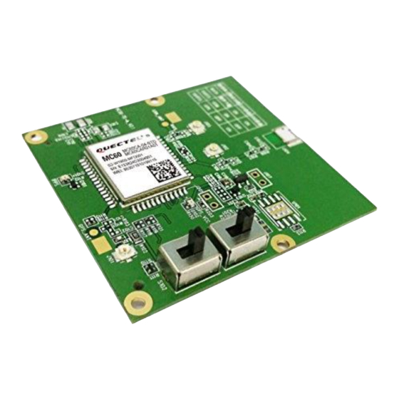
GSM/GPRS/GNSS Module Series MC60-TE-A User Guide Product Concept 2.1. MC60-TE-A Top and Bottom View Figure 1: MC60-TE-A Top View A: Serial selector switch B: GSM antenna interface C: GNSS antenna interface D: BT antenna interface E: LED indicator MC60-TE-A_User_Guide Confidential / Released... -
Page 10: Figure 2: Mc60-Te-A Bottom View
GSM/GPRS/GNSS Module Series MC60-TE-A User Guide Figure 2: MC60-TE-A Bottom View F: SIM2 card interface G: Test points NOTES Some interfaces and test pins are reserved only for engineers to debug some functions which are not used for customers. Some functions are only supported in certain software versions. -
Page 11: Interface Application Of Mc60-Te-A
GSM/GPRS/GNSS Module Series MC60-TE-A User Guide Interface Application of MC60-TE-A 3.1. SIM2 Card Interface Figure 3: SIM2 Card Interface Table 1: Pins of SIM2 Card Interface Signal Description Connect to ground Reserved SIM_DATA SIM card data I/O SIM_CLK SIM card clock... -
Page 12: Test Points
GSM/GPRS/GNSS Module Series MC60-TE-A User Guide SIM_RST SIM card reset Ground SIM_VDD Power supply for SIM card Ground Ground 3.2. Test Points Figure 4: Test Points Table 2: Pins of Test Points Signal Description PCM_CLK/SPI_CS PCM clock PCM_SYNC/SPI_MISO O PCM frame synchronization... - Page 13 GSM/GPRS/GNSS Module Series MC60-TE-A User Guide PCM_IN/SPI_CLK PCM data input Ground GNSS_VCC_EN GNSS power enabled PCM_OUT/SPI_MOSI General purpose input/output port RXD_AUX Receive data I2C_SCL28 Reserved I2C_SDA28 Reserved MC60-TE-A_User_Guide Confidential / Released 12 / 25...
-
Page 14: Mc60-Te-A Accessories Assembly
GSM/GPRS/GNSS Module Series MC60-TE-A User Guide MC60-TE-A Accessories Assembly Figure 5: MC60-TE-A Toolkit Accessories A: GNSS antenna B: CD C: GNSS antenna patch lead MC60-TE-A_User_Guide Confidential / Released 13 / 25... -
Page 15: Illustration
GSM/GPRS/GNSS Module Series MC60-TE-A User Guide Illustration MC60-TE-A kit is intended to be used in combination with GSM EVB for MC60 module testing and evaluation. The connection between MC60-TE-A and GNSS/GSM antenna can refer to the following figure. Figure 6: Connection between MC60-TE-A and GNSS/GSM Antenna 5.1. -
Page 16: Communicate With Gsm Part Of The Module
If the UART3 is used for communication with the GSM part, please turn the S101 switch to OFF and S102 switch to ON state on MC60-TE-A, and then connect the UART3 on EVB to PC’s USB port with the USB to UART converter cable. -
Page 17: Figure 9: S101/S102 Switch Status On Uart3 When Communicating With Gsm Part
(2) Open the QCOM (AT command window) on PC. Set appropriate Baud Rate (such as 115200bps) and COM number which can be checked by the Device Manager on PC. (3) Connect the antenna to the GSM_ANT on MC60-TE-A with an RF cable. (4) Insert SIM card into the SIM card socket. -
Page 18: Communicate With Gnss Part Of The Module
5.3.1. Use Main UART (All-in-one Solution) (1) Turn the S101 and S102 switch to ON state on MC60-TE-A, and then connect the main UART of EVB to PC’s USB port with the USB to UART converter cable. This is the recommended method. -
Page 19: Figure 11: S101/S102 Switch Status On Uart3 When Communicating With Gnss Part
D503 on the EVB will be lighted. (4) Send AT+QGNSSC=1 command via main UART to power on the GNSS part, the LED D102 on MC60-TE-A will be lighted. For details of the corresponding AT commands, please refer to document [1]. -
Page 20: Use Main Uart And Uart3
(1) Use a short circuit cap to connect the J106. Figure 13: J106 Short Circuit Connection (2) Turn the S101 and S102 switch to ON state on MC60-TE-A, and then connect the main UART and UART3 of EVB to PC’s USB ports with the USB to UART converter cables. -
Page 21: Firmware Upgrade Through Main Uart Port
EVB will be lighted. (5) Send AT+QGNSSC=1 command via main UART to power on the GNSS part, the LED D102 on MC60-TE-A will be lighted. For details of the corresponding AT commands, please refer to document [1]. (6) Send AT commands about GNSS and get the data of GNSS via main UART (7) NMEA data will be received via UART3. -
Page 22: Compatible Design And Applications
Figure 16: Using a Passive Antenna When testing the BT function, the built-in Bluetooth antenna of MC60-TE-A is recommended to be used. In this case, resistor R109 (0 ohm, 0402 package) is mounted, while resistor R105 (0 ohm, 0402 package) is not mounted. -
Page 23: Figure 18: Using An External Bluetooth Antenna
GSM/GPRS/GNSS Module Series MC60-TE-A User Guide Figure 18: Using an External Bluetooth Antenna MC60-TE-A_User_Guide Confidential / Released 22 / 25... -
Page 24: 60-Pin Assignment
GSM/GPRS/GNSS Module Series MC60-TE-A User Guide 60-pin Assignment Figure 19: DIP Connector of MC60-TE-A Table 3: Pin Definition of the 60-pin DIP Connector Pin No. Pin Name Pin No. Pin Name VBAT VBAT VBAT VBAT VBAT ADC0 VRTC VDD_EXT NETLIGHT... - Page 25 GSM/GPRS/GNSS Module Series MC60-TE-A User Guide PWRKEY KBR0 KBR1 GPIO0 KBR2 TXD3 SIM1_VDD RXD3 SIM1_RST KBC0 SIM1_DATA KBC1 SIM1_CLK SIM1_PRESENCE I SD_CMD SD_CLK SD_DATA DBG_RXD DBG_TXD SPK1P MICP SPK1N MICN SPK2P MICP MICN MC60-TE-A_User_Guide Confidential / Released 24 / 25...
-
Page 26: Appendix A References
GSM/GPRS/GNSS Module Series MC60-TE-A User Guide Appendix A References Table 4: Related Documents Document Name Remark Quectel_MC60_AT_Commands_Manual MC60 AT commands manual Quectel_GSM_UART_Application_Note Serial port application note Quectel_MC60_Hareware_Design MC60 Hardware design Quectel_GSM_EVB_User_Guide GSM EVB user guide MC60-TE-A_User_Guide Confidential / Released 25 / 25...
Need help?
Do you have a question about the MC60-TE-A and is the answer not in the manual?
Questions and answers