
Related Manuals for Quectel M.2 EVB


Summary of Contents for Quectel M.2 EVB
- Page 1 M.2 EVB User Guide LTE Module Series Rev: M.2_EVB_User_Guide_V1.0 Date: 2018-07-13 Status: Released www.quectel.com...
-
Page 2: About The Document
QUECTEL OFFERS THE INFORMATION AS A SERVICE TO ITS CUSTOMERS. THE INFORMATION PROVIDED IS BASED UPON CUSTOMERS’ REQUIREMENTS. QUECTEL MAKES EVERY EFFORT TO ENSURE THE QUALITY OF THE INFORMATION IT MAKES AVAILABLE. QUECTEL DOES NOT MAKE ANY WARRANTY AS TO THE INFORMATION CONTAINED HEREIN, AND DOES NOT ACCEPT ANY LIABILITY FOR ANY INJURY, LOSS OR DAMAGE OF ANY KIND INCURRED BY USE OF OR RELIANCE UPON THE INFORMATION. - Page 3 LTE Module Series M.2 EVB User Guide About the Document History Revision Date Author Description Storm BAO/ 2018-07-13 Initial Claude WEI M.2_EVB_User_Guide 1 / 37...
-
Page 4: Table Of Contents
General Overview ..........................8 Key Features ..........................8 2.1. Interface Overview ........................9 2.2. Top and Bottom Views of M.2 EVB ................... 11 2.3. EVB Kit Accessories ........................ 12 2.4. EVB Kit Accessories Assembly ...................... 15 Application Interfaces ........................16 Power Interface (J101/J701) .................... - Page 5 LTE Module Series M.2 EVB User Guide Table Index TABLE 1: KEY FEATURES OF M.2 EVB ......................8 TABLE 2: INTERFACES OF M.2 EVB ......................... 9 TABLE 3: ACCESSORIES LIST ........................13 TABLE 4: PIN ASSIGNMENT OF J701 ......................18 TABLE 5: PIN DEFINITION OF J302 ........................
- Page 6 FIGURE 3: M.2 EVB BOTTOM VIEW ....................... 12 FIGURE 4: M.2 EVB KIT ACCESSORIES ......................13 FIGURE 5: M.2 EVB KIT ACCESSORIES ASSEMBLY ..................15 FIGURE 6: POWER SUPPLY FOR M.2 EVB ....................16 FIGURE 7: POWER INTERFACE ........................17 FIGURE 8: POWER PLUG DESIGN .........................
-
Page 7: Introduction
M.2 EVB User Guide Introduction This document describes how to use the M.2 EVB (Evaluation Board). It is an assistant tool for engineers to develop and test Quectel EM05 and EM06 modules, which are designed in M.2 form factor. 1.1. Safety Information The following safety precautions must be observed during all phases of operation, such as usage, service or repair of any cellular terminal or mobile incorporating EM05 and EM06 modules. - Page 8 LTE Module Series M.2 EVB User Guide The cellular terminal or mobile contains a transmitter and receiver. When it is ON, it receives and transmits radio frequency signals. RF interference can occur if it is used close to TV set, radio, computer or other electric equipment.
-
Page 9: General Overview
LTE Module Series M.2 EVB User Guide General Overview Quectel supplies M.2 EVB for designers to develop applications based on Quectel EM05 and EM06 modules. The EVB can test all functionalities of these modules. 2.1. Key Features The following table describes the detailed features of M.2 EVB. -
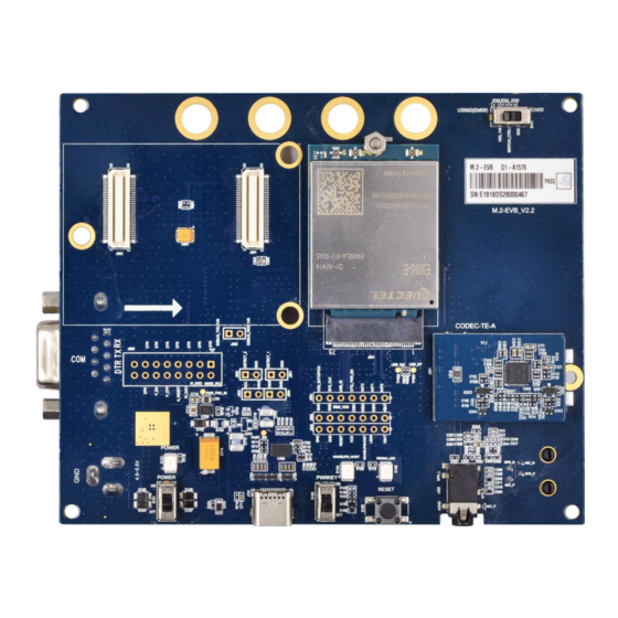
Page 10: Interface Overview
Power Power RESET USB Type-C PWRKEY Supply Audio Interface Switch Figure 1: M.2 EVB Interface Overview Table 2: Interfaces of M.2 EVB Interface Reference No. Description The power jack on the EVB. J101 (bottom side) Typical supply voltage: +5V Power Supply... - Page 11 (U)SIM card connector 2 J402 (bottom side) (Not applicable to EM05 module) COM Port J201 (bottom side) Debug UART port (only for internal debugging by Quectel) D101 (Power ON/OFF indicator) is used to indicate power ON/OFF status of the EVB D101, Status Indication...
-
Page 12: Top And Bottom Views Of M.2 Evb
LTE Module Series M.2 EVB User Guide 2.3. Top and Bottom Views of M.2 EVB The top and bottom views of the M.2 EVB are shown as following figures. Figure 2: M.2 EVB Top View M.2_EVB_User_Guide 11 / 37... -
Page 13: Evb Kit Accessories
LTE Module Series M.2 EVB User Guide Figure 3: M.2 EVB Bottom View 2.4. EVB Kit Accessories All accessories of the M.2 EVB kit are listed as below. M.2_EVB_User_Guide 12 / 37... - Page 14 Main Antennas USB Driver Disk Instruction Sheet USB to RS-232 Converter Cable USB Type-C Cable Bolts and Nuts Figure 4: M.2 EVB Kit Accessories Table 3: Accessories List Items Description Quantity USB type-C cable Cables USB to UART converter cable...
- Page 15 LTE Module Series M.2 EVB User Guide A sheet of paper giving instructions for EVB Instruction Sheet connection, details of EVB accessories, etc. NOTE The main antenna can also be used for diversity reception. M.2_EVB_User_Guide 14 / 37...
-
Page 16: Evb Kit Accessories Assembly
LTE Module Series M.2 EVB User Guide EVB Kit Accessories Assembly The following figure shows the EVB kit accessories assembly. Figure 5: M.2 EVB Kit Accessories Assembly M.2_EVB_User_Guide 15 / 37... -
Page 17: Application Interfaces
M.2 EVB. 4.1. Power Interface (J101/J701) The M.2 EVB can be powered by an external power adapter through connecting with the power jack (J101) or USB receptacle (J701) on the EVB. The power adapter connects to a step-down converter which can provide the supply voltage (VBAT) required for operating the EVB and the module. -
Page 18: Interface (J501)
Figure 7: Power Interface Before connecting the power supply, customers have to select a proper DC power adapter to supply power for the M.2 EVB, and the power plug design of the adapter is shown as below. Inner contact Outer contact Figure 8: Power Plug Design 4.2. -
Page 19: Usb Interface (J701)
USB* The M.2 EVB provides a USB Type-C interface J701 for connection with a host device. The USB data lines D+ and D- are connected directly to the EM06 module. The CC1 and CC2 lines can be used for Type-C configuration channel signals. -
Page 20: Audio Interfaces (J301/J302/J303)
The USB interface of EM05 does not support voice over USB function. 4.4. Audio Interfaces (J301/J302/J303) Quectel M.2 EVB provides one digital audio codec board interface (PCM) J301 and two analog audio interfaces J302 and J303. This chapter gives a detailed introduction on these audio interfaces. -
Page 21: Earphone Interface (J302)
LTE Module Series M.2 EVB User Guide BTB CON BTB CON TLV3104 Module MIC_BIAS IN2P PCM_CLK BCLK IN2N U101 PCM_SYNC LRCK J303 MIC HPO_L PCM_OUT DACDAT1 HPO_R PCM_IN ADCDAT1 J302 I2C_SCL LOUDL/P LOUDR/N I2C_SDA J301 J301 VDD_EXT Figure 11: Reference Design for Connection between Codec Board and EVB Figure 12: Connection between Codec Board and EVB 4.4.2. - Page 22 LTE Module Series M.2 EVB User Guide Close to Socket Differential layout AGND J301 U101 10pF 33pF 4.7uF 75pF 15pF AGND MIC_N MIC_P J302 Codec 22uF NM_0R Close to Socket TE-A SPK_L 22uF SPK_R 10pF 33pF Audio Jack 10pF 33pF...
-
Page 23: Handset Interface (J303)
Right channel of stereo audio output SPK_L Left channel of stereo audio output 5, 6 Not connected The following figure shows the sketch design of audio plug which suits for the audio jack on M.2 EVB. SPK_L 32Ω SPK_R 32Ω... -
Page 24: U)Sim Interfaces (J401/J402)
4.5. (U)SIM Interfaces (J401/J402) The M.2 EVB has two 8-pin push-push type (U)SIM card (3.0V or 1.8V) connector J401 and J402. Both of them can be used for EM06 module, and EM06 supports Dual SIM Single Standby* function. The J402 is not applicable for EM05 module. - Page 25 J402 J401 Figure 18: Pin Assignments of J401/J402 Table 7: Pin Assignments of J401/J402 Pin No. Signal Name Description SIM_VDD (U)SIM card power supply, provided by M.2 EVB SIM_RST (U)SIM card reset SIM_CLK (U)SIM card clock Ground Not connected SIM_DATA...
-
Page 26: Switches And Button
LTE Module Series M.2 EVB User Guide 4.6. Switches and Button The M.2 EVB includes three switches S101/S103/S701 and a button S102, as shown in the following figure. S101 S102 S103 S701 Figure 19: Switches and Button Table 8: Description of the Switches and Button Reference No. -
Page 27: Test Points
Extinct: RF function is disabled 4.8. Test Points The M.2 EVB provides a series of test points. They can help customers to obtain the corresponding waveform of some signals. The following figures and tables show test points J502, J503, J504, J505, J202, J601, J602, J603 and J604. - Page 28 LTE Module Series M.2 EVB User Guide J502 Figure 21: Test Point J502 Table 10: Pin Definition of J502 Pin No. Pin Name Description Data terminal ready test pin GNSS_IRQ GNSS_IRQ test pin Data terminal ready test pin W_DIS2 GPS control test pin...
- Page 29 LTE Module Series M.2 EVB User Guide Data terminal ready test pin Dynamic power control test pin Not connected Not connected J504 J503 J505 Figure 22: Test Points J503, J504 and J505 Table 11: Pin Definition of J503 Pin No.
- Page 30 LTE Module Series M.2 EVB User Guide Ground Table 12: Pin Definition of J504 Pin No. Pin Name Description ANT0 Tunable antenna control ANT1 Tunable antenna control ANT2 Tunable antenna control OTG_PWR_EN USB power supply enable pin USB_ID USB_ID test pin...
- Page 31 LTE Module Series M.2 EVB User Guide J202 J602 J601 J603 J604 Figure 23: Test Points J202, J601, J602, J603 and J604 Table 14: Pin Definition of J202 Pin No. Pin Name Description DEBUG_TXD_1V8 DEBUG_TXD_1V8 test pin DEBUG_RXD_1V8 DEBUG_RXD_1V8 test pin Table 15: Pin Definition of J601 Pin No.
- Page 32 LTE Module Series M.2 EVB User Guide Table 16: Pin Definition of J602 Pin No. Pin Name Description DETECT_2 Module insertion detection pin Ground Table 17: Pin Definition of J603 Pin No. Pin Name Description Module power supply test pin...
-
Page 33: Operation Procedures Illustration
LTE Module Series M.2 EVB User Guide Operation Procedures Illustration This chapter introduces how to use the M.2 EVB for testing and evaluation of Quectel EM05 and EM06 modules. 5.1. Power on the Module 1. Connect the module to the EVB. Insert the module into the connectors (J501) on EVB, and then fix the other end of the module with screws. -
Page 34: Communication Via Usb Type-C Interface
[1]. Figure 24: USB Ports Install and then use the QCOM tool provided by Quectel to realize communication between the module and the PC. The following figure shows the COM Port Setting field on QCOM: select correct “COM Port” (USB AT Port which is shown in above figure) and set correct “Baudrate” (such as 115200bps). -
Page 35: Reset The Module
LTE Module Series M.2 EVB User Guide 3. Click the “Load FW Files” button to choose the firmware package. 4. Click the “Start” button to upgrade the firmware. Figure 26: Configurations for Firmware Upgrade For more details about QFlash tool usage and configuration, please refer to document [5]. -
Page 36: Power Off The Module
NOTE Please refer to document [2] for details about AT+QPOWD command. 5.6. Test Current Consumption The M.2 EVB can also be used to test the current consumption of the module after making the following modifications. 1. Remove R607. Figure 27: Location of R607 M.2_EVB_User_Guide... - Page 37 LTE Module Series M.2 EVB User Guide Connect an external power supply to J603 or J604 (either of them) to supply power for the module independently. Figure 28: Location of J603 and J604 2. Power on the module according to the procedure mentioned in Chapter 5.1 and then test the current consumption of the module.
-
Page 38: Appendix A References
LTE Module Series M.2 EVB User Guide Appendix A References Table 20: Related Documents Document Name Remark Quectel_LTE_Windows_USB_Drivers_Installation_ Install USB drivers for M.2 module on Guide Windows system Respective AT commands manual for Quectel_xx_AT_Commands_Manual EM05 and EM06 modules Respective hardware design for EM05 and...
Need help?
Do you have a question about the M.2 EVB and is the answer not in the manual?
Questions and answers