Chapters
Table of Contents

Related Manuals for DINSEO DIX TIG GO 1906.M HF


Summary of Contents for DINSEO DIX TIG GO 1906.M HF
- Page 1 BA-0130 Operations manual TIG Welding Power Source DIX TIG GO 1906.M HF DIX TIG GO 2506.M HF Keep in secure area for future reference! S C H W E I S S E N W E L D I N G...
-
Page 2: Table Of Contents
Digital interface PCB replacement ideal performance in MMA weld, with any type of electrode. The DIX TIG GO 1906.M HF units are the ideal solution for all profes- Procedure for cover assembly and disassembly sional welding applications and for maintenance work that calls Meaning of graphic symbols on welding power source 9 for power and portability. -
Page 3: Usage Limits (Iec 60974-1)
The general technical data of the system are summarized in ta- - Anti-sticking function to avoid the electrodes sticking. ble 1. DIX TIG GO 1906.M HF • The PFC device makes the wave form of the current absorbed How to lift up the welding power source... -
Page 4: Open The Packaging
The system essentially consists of: Use the welder’s own plug to connect it up to the main power sup- • DIX TIG GO 1906.M HF or DIX TIG GO 2506.M HF weld unit. ply. Proceed as follows if you have to replace the plug: • Separately:... - Page 5 FIG. A...
-
Page 6: Interfacing Accessories (Optional)
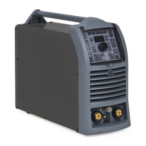
Interfacing accessories (optional) Automation analogue / digital robot interface Fitted on the back of the DIX TIG GO 2506.M HF welding power source (see example, Pos. 1, Fig. B). Automation analogue / digital robot interface connection cable - Cutting robot or for automatic equipment Connect the cable to the analogue / digital interface as shown in figure (Pos. -
Page 7: Electrode Welding (Mma)
TIG WELDING WITH “Lift” TYPE STRIKING 3) Make the adjustments and select the parameters on the con- 4a) Open the gas cylinder and flow regulator. trol panel (for further information see the control panel manu- 5a) Put the electrode at the point at which welding is to begin, put al). -
Page 8: Maintenance
Maintenance NOTE: The value shown on the display during welding represents the effective current output with all types of control. ATTENTION: Before carrying out any inspection of the inside of The digital control unit of the welding power source is fitted with a the welding power source, disconnect the system from the supply. -
Page 9: Meaning Of Graphic Symbols On Welding Power Source
Meaning of graphic symbols on welding power source Connector for the remote control Power supply switch System for use in environments with increased Warning! risk of electroshock Product suitable for free circulation in the Euro- Fast coupling TIG torch gas tube pean Community Before using the equipment you should carefully Danger! High voltage... -
Page 10: Wiring Diagram (Dix Tig Go 1906.M Hf)
Wiring diagram (DIX TIG GO 1906.M HF) - Page 11 2101WA31...
-
Page 12: Wiring Diagram (Dix Tig Go 2506.M Hf)
Wiring diagram (DIX TIG GO 2506.M HF) - Page 13 2101WB24...
-
Page 14: Key To The Electrical Diagram
•1 •2 •3 •4 •5 •6 •7 •8 •9 •10 •11 •12 •13 •14 •15 •16 •17 •18 •19 •20 FCTA L1-2 •21 •22 •23 •24 •25 •26 •27 •28 •29 •30 •31 •32 •33 •34 •35 •36 •37 •38 •39 •40 S-AI... -
Page 15: Control Panel
Control panel Calling up saved programs Introduction Viewing the parameters set Displaying the software version installed Activating the VRD device Electrode welding (MMA) Auxiliary functions TIG welding Factory default TIG LIFT DC welding with the SPOT WELDING Error and protection conditions function on Spot welding with DIX ARC COOL SPOT function with TIG HF DC welding... - Page 16 ■ WELDING MODE ■ ENCODER knob The welding power source offers 4 welding modes. Each time This is used to regulate and change the welding the button is pushed, the welding power source switches to parameters, according to which LED is switched select the welding mode indicated by the LED that stays lit, in the on and the value shown on the DISPLAY, which following order:...
-
Page 17: Displaying The Software Version Installed
1B - STANDARD CONFIGURATION TIG welding When one of the 2 TIG welding processes available on the weld- ing power source is activated, this allows you to select the follow- ing welding parameters, based on which LED is flashing: PRE-GAS duration WARNING: This special parameter is only to be activated by SLOPE UP duration qualified personnel, or those trained by technicians. -
Page 18: Tig Welding
4) WELDING PARAMETERS SELECTION 4) Turn the ENCODER Knob (E) until the DISPLAY (D) shows To refine the weld quality, the following parameters can be set the CURRENT VALUE at which you wish to weld. by pushing the WELDING PARAMETERS SELECTION key (T7) in succession: • HOT START - This increases the welding current, in per- centage terms, for a time interval that can be set at the start... -
Page 19: Spot Welding With Dix Arc Cool Spot Function With Tig Hf Dc Welding
Spot welding with DIX ARC COOL SPOT Multi spot welding with Multi-DIX ARC function with TIG HF DC welding COOL SPOT function with TIG HF DC welding Innovative TIG HF DC tack weld device that makes it possible to do precise, safe tack welding with very little heat applied. Thanks The Multi-DIX ARC COOL SPOT function can be used for cold to the “Perfect-Point”... -
Page 20: Tig Welding - Welding Parameters
WARNING: This can only be programmed when 4 STROKES or TIG welding - Welding parameters SWITCH welding mode is activated. The can be configured in the following 2 ways: POST GAS duration (0,5 ÷ 25,0 sec) • STANDARD (Std) configuration. WARNING: When the post-gas LED flashes and the LED I is on • SPECIAL (SPE) configuration. - Page 21 To exit the setting phase, hold the WELDING PARAMETERS SELECTION key (T7) down for about 1 second. 2B) FAST PULSE TIG pulse welding with manual setting of parameters. Press the PULSE key (T3) until the requited pulsation is active. FAST SLOW Press the WELDING PARAMETERS SELECTION PULSE...
- Page 22 following (in addition to the WELDING PARAMETERS defined as being “BASIC”): WELDING PARAMETERS with PULSE mode and L10 L18 L19 SWITCH welding mode active (SWITCH LED on) When this welding mode is active it is possible to work at 2 differ- ent pulse current levels ( I and I ).
- Page 23 To exit the setting phase, hold the WELDING PARAMETERS SE- LECTION key (T7) down for about 1 second. 3D - SYN PULSE + SWITCH Press the PULSE key (T3) until the requited pulsation is active (SYN LED on). FAST Press the WELDING MODE SELECTION key SLOW (T6) until the SWITCH welding mode is active PULSE...
-
Page 24: Editing The Maximum And Minimum Limits For Welding Parameters
Editing the maximum and minimum limits for welding parameters Welding power source in STANDARD (Std) configuration: During TIG welding with HF ignition, the units allow you to modify the MINIMUM and MAXIMUM LIMITS for some WELDING PARAMETERS, thereby providing a more skilled welder and a more versatile welding power source. -
Page 25: Calling Up Saved Programs
4) You can now set or edit the individual parameters or create Activating the VRD device new programs. 5) Rotate the ENCODER Knob (E) to scroll the programs until To activate the VRD device, which must be done when the weld- you find an empty, unused program slot. -
Page 26: Factory Default
Factory default Error and protection conditions WARNING: This operation results in complete resetting of all parameters to the factory settings. To reset the settings, you must: • When the welding power source is off, push and hold the WELD- ING PROCESS SELECTION (T5) and WELDING MODE SELECTION (T6) keys down together.
Need help?
Do you have a question about the DIX TIG GO 1906.M HF and is the answer not in the manual?
Questions and answers