Advertisement
Quick Links
Installation Instructions
Model DLC
Device Loop Card
INTRODUCTION
OPERATION
P/N 315-033090-17
The Model DLC Device Loop Card from Siemens Industry,
Inc., is the interface for connection of FireFinder-XLS/Desigo
Fire Safety Modular/Cerberus PRO Modular smoke detec-
tors, Multi-Criteria detectors including Carbon Monoxide,
manual stations, monitor devices, and control devices to the
FireFinder-XLS/Desigo Fire Safety Modular/Cerberus PRO
Modular System. The DLC uses one network address on the
system. The application program that is loaded into the on-
board microprocessor controls the DLC operation.
The DLC contains 12 LEDs for diagnosis of problems.
Ground fault detection is provided by the loop.
All field devices connected to the DLC are addressed and
tested using the Device Programming Unit (DPU).
The DLC initializes, operates, and maintains all devices
residing on the loop. The DLC communicates all relevant
device and event information, such as alarms and troubles,
to the System CPU. The sensitivity of any intelligent smoke
detector and the logic functions of any intelligent output
devices can be checked and adjusted from the Operator
Interface (OI) through the DLC. All information about the
devices on the loop can be displayed on the OI. The DLC
allows the System polarity insensitive devices to be
connected without generating errors.
The DLC supports only one loop (two isolated parallel
zones) of up to 252 FireFinder-XLS/Desigo Fire Safety
Modular/Cerberus PRO Modular intelligent field devices as
well as device accessories (relay bases, audible bases, and
remote lamps) in any combination. The microprocessor
controls the on-board isolator to isolate either zone from
the loop if one of them is shorted. When one zone is
isolated from the loop, the other zone will still work.
The on-board microprocessor provides the DLC with the
ability to function and initiate alarm conditions even if the
main FireFinder-XLS/Desigo Fire Safety Modular/Cerberus
PRO Modular CPU fails.
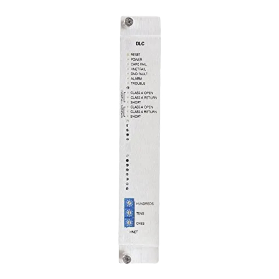
DLC
RESET
POWER
CARD FAIL
HNET FAIL
GND FAULT
ALARM
TROUBLE
ZONES STATUS
Z
CLASS A OPEN
O
N
CLASS A RETURN
E
SHORT
1
CLASS A OPEN
Z
O
CLASS A RETURN
N
E
SHORT
2
HNET
Figure 1
DLC Device Loop Card
Siemens
Siemens
Industry
Industry
Industry, , , , , Inc.
Siemens Industry
Siemens
Siemens
Industry
Building
Building
Building
Building
Building T T T T T ec
echnologies Di
ec
ec
ec
hnologies Di
hnologies Di
hnologies Division
hnologies Di
HUNDREDS
TENS
ONES
Inc.
Inc.
Inc.
Inc.
vision
vision
vision
vision
Advertisement

Related Manuals for Siemens DLC


Summary of Contents for Siemens DLC
-
Page 1: Installation Instructions
Operator Interface (OI) through the DLC. All information about the devices on the loop can be displayed on the OI. The DLC HUNDREDS allows the System polarity insensitive devices to be connected without generating errors. - Page 2 Multi-Criteria detectors (Table 1) are supported by the OI, FW version 9.02 and later, and the DLC with Firmware version 06.xx and later. The DLC can be made backwards compatible in systems using OI, P/N 500-033070, with DLC Firmware version 05.06 or earlier.
- Page 3 Three rotary dial switches at the bottom of the front panel are used to set the HNET network address of the DLC. All field devices connected to the DLC are addressed and tested using the Device Programming Unit (DPU). Refer to the DPU Manual, P/N 315-033260 for further information.
-
Page 4: Pre-Installation
Remove all system power before installation, first battery then AC. (To power up, connect the AC first, then the battery.) All field wiring to the DLC is connected to the terminal blocks of the CC-5 card cage slot in which it is installed. - Page 5 24V+ 24V- DO NOT USE TO 24VDC FROM THE PSC-12 Figure 3 Wiring The 24VDC Power Lines To The DLC Slot In The CC-5 CLASS A WIRING* CLASS B WIRING** NO T-TAPPING ALLOWED T-TAPPING ALLOWED BOTH ZONES MUST BE WIRED AS CLASS A...
- Page 6 The DLC circuit can be wired Style 4 (Class B) or Style 6 (Class A). On-board switches controlled by microprocessor allow selection of Class A or B without using jumpers for Class B. The DLC field circuit wiring does not require twisted, shielded wire.
-
Page 7: Electrical Ratings
ELECTRICAL RATINGS i l r Siemens Industry, Inc. P/N 315-033090-17 Building Technologies Division... - Page 8 Max Current Load of Devices DLC LINE RESISTANCE vs MAX CURRENT LOAD OF DEVICES Note 1: The total number of devices in two zones can not exceed 252. Note 2: The total current load in two zones cannot exceed 350ma.
- Page 9 Cyber security disclaimer Siemens products and solutions provide security functions to ensure the secure operation of building comfort, fire safety, security management and physical security systems. The security functions on these products and solutions are important components of a comprehensive security concept.
- Page 10 Siemens Industry, Inc. Siemens Canada, Ltd. Siemens AG P/N 315-033090-17 Building Technologies Division 1577 North Service Road East I BT FS SYS MCH Document ID A6V10239107 Florham Park, NJ Oakville, Ontario D-81379 München L6H 0H6 Canada...
Need help?
Do you have a question about the DLC and is the answer not in the manual?
Questions and answers