Table of Contents
Advertisement
Quick Links
SIMATIC NET
DP/AS-Interface Link 20E
Manual
Release 08/2008
C79000-G8976-C235−01
Preface, Contents
Technical Description, Installation
Instructions, Operation
Data Exchange between
DP Master and AS-i Slave
Using the Command Interface
Slave Diagnostics
Eliminating Problems /
Error Displays
Appendix
AS-Interface Protocol
Implementation Conformance
Statements
References
Note on the CE Mark
Glossary
Index
The following supplements belong
to this documentation
(Edition 01/2023):
1 Approvals
1.1 Ex certificates
1
2
3
4
5
A
B
C
D
Advertisement
Table of Contents

Related Manuals for Siemens SIMATIC NET DP/AS-i Link 20E


Summary of Contents for Siemens SIMATIC NET DP/AS-i Link 20E
- Page 1 Preface, Contents Technical Description, Installation Instructions, Operation SIMATIC NET Data Exchange between DP Master and AS-i Slave DP/AS-Interface Link 20E Using the Command Interface Slave Diagnostics Manual Eliminating Problems / Error Displays Appendix AS-Interface Protocol Implementation Conformance Statements References Note on the CE Mark Glossary Index The following supplements belong...
- Page 2 Classification of Safety-Related Notices This manual contains notices which you should observe to ensure your own perso- nal safety, as well as to protect the product and connected equipment. These noti- ces are highlighted in the manual by a warning triangle and are marked as follows according to the level of danger: Danger indicates that death or severe personal injury will result if proper precautions are...
- Page 3 Siemens. This product can only function correctly and safely if it is transported, stored, set up, and installed correctly, and operated and maintained as recommended.
- Page 4 You will find the ordering data for this documentation in the relevant catalogs or contact your local Siemens office. Copyright E Siemens AG 2001−2008 All rights reserved Disclaimer of Liability The reproduction, transmission or use of this document or its contents is not We have checked the contents of this manual for agreement with the hard- permitted without express written authority.
- Page 5 Preface Purpose of the manual This manual supports you when using the DP/AS−Interface Link 20E module, in places shortened to DP/AS−i Link 20E in the following chapters. It contains information about how PROFIBUS DP masters can address AS-i actuators and AS-i sensors via this module.
- Page 6 CD with the GSD file The accompanying CD contains the GSD file that you require to configure the DP/AS−i Link 20E with your DP master, if the DP master is not a Siemens device (see Section 1.10.1 ). DP/AS-Interface Link 20E Release 08/2008 C79000-G8976-C235−01...
-
Page 7: Table Of Contents
Contents Technical description, installation instructions, operation ....General notes on operation − safety warnings ....Use of the module . - Page 8 Contents 2.4.3 Programming examples ........PROFIBUS DP control commands .
- Page 9 Contents Error Displays/Remedying Errors ....... AS-Interface Protocol Implementation Conformance Statement (PICS) References .
-
Page 10: Technical Description, Installation Instructions, Operation
Technical description, installation instructions, operation This chapter explains the performance, installation and basic functions of the master module DP/AS−Interface Link 20E (DP/AS-i Link 20E). You will learn the following, ... S How to install the DP/AS-i Link 20E; S The display and control elements of the DP/AS-i Link 20E; S How to configure the DP/AS-i Link 20E with the push button;... -
Page 11: General Notes On Operation − Safety Warnings
Technical description, installation instructions, operation General notes on operation − safety warnings Caution When handling and installing the DP/AS-i Link 20E , make sure that you adhere to the ESD guidelines. The DP/AS-i Link 20E must only be connected when the AS-i power supply unit is turned off. -
Page 12: Use Of The Module
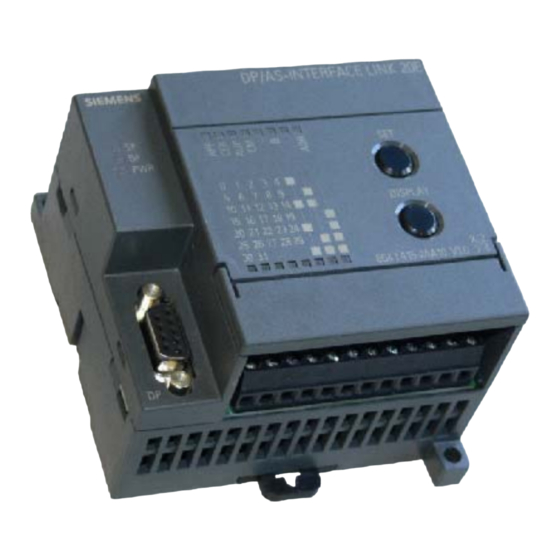
The following AS-i slaves can be used: − Standard slaves / AS-i analog slaves − Slaves with the extended addressing mode Wider networking via PROFIBUS DP SIEMENS DP AS/INTERFACE LINK 20E 6GK1 415-2AA10 V3.0 DP/AS-Interface Link 20E Active module... - Page 13 Technical description, installation instructions, operation Features DP/AS-i Link 20E allows the exchange of I/O data with a DPV0, DPV1 master and the AS-i slaves with byte or word consistency. S DPV0 mode In DPV0 mode, with a maximum of 32/32 bytes I/O, up to 62 digital AS-i slaves can be served at a transmission speed of 9.6 Kbps to 12 Mbps.
-
Page 14: Technical Data Of The Module
Technical description, installation instructions, operation Technical data of the module The DP/AS-i Link 20E has the following technical data: Table 1-1 Feature Explanation/values AS-i cycle time 5 ms with 31 slaves 10 ms for 62 slaves with the extended addressing mode Configuration of the AS-Interface Using a button on the front panel or with STEP 7 Supported AS-i master profiles... -
Page 15: Approvals
Technical description, installation instructions, operation Approvals Table 1-2 Description of the approvals c−UL−us UL 508 CSA C22.2 No. 142 c−UL−us for hazardous locations ANSI / ISA 12.12.01, CSA C22.2 No. 213−M1987 CL. 1, Div. 2 GP.A.B.C.D T4 CL. 1, Zone 2, GP.IIC, T4 CL. -
Page 16: Installing The Module
Technical description, installation instructions, operation Installing the module Options DP/AS-i Link 20E has degree of protection IP20. S You can install the DP/AS-i Link 20E on a standard rail (DIN rail complying with EN 50022). S As an option, you can also install the module on a wall directly using the mounting holes in the casing. -
Page 17: Front Panel − Access To All Functions
SET button DISPLAY button S for AS-i configuration S switches over the S for setting the display PROFIBUS address SIEMENS DP AS/INTERFACE LINK 20E Status display S 7 LEDs Slave display S LED “B” S 3 group LEDs Display S 5 slave LEDs 6GK1 415-2AA10 V3.0... -
Page 18: Connection To As-Interface And Profibus
Technical description, installation instructions, operation Connection to AS-Interface and PROFIBUS Connections DP/AS-i Link 20E has the following connectors: S Two connectors to the AS-i cable (bridged internally) S Connectors for functional ground S One connection to PROFIBUS (9-pin sub D female connector) The AS-i connectors are located below the lower cover of the front panel of the DP/AS-i Link 20E. - Page 19 Technical description, installation instructions, operation Unused connectors 8, 9, 10, 11 PROFIBUS DP Functional ground AS-i cables Figure 1-3 Connection of the AS-i cable Functional ground The DP/AS-i Link 20E has four connectors for functional ground. One of these connectors should be connected to the PE conductor with as little resistance as possible.
-
Page 20: Display And Controls
Technical description, installation instructions, operation Display and controls 1.8.1 Display modes and meaning of the LEDs Meaning of the LED display S The status display The status display indicates statuses and error messages of the Link module itself and the connected AS-i line. The following LEDs belong to the status display: −... -
Page 21: Status Display
Technical description, installation instructions, operation 1.8.2 Status display Meaning of the 7 status LEDs The 7 status LEDs have the following meaning: Table 1-3 Meaning of the status LEDs LED (color) Status Meaning BF (red) Bus Failure Indicates errors on PROFIBUS DP. The LED is lit when the connection between the DP master and the DP/AS-i Link 20E is interrupted or the DP master is inactive;... -
Page 22: Slave Display For As-I Slaves
Technical description, installation instructions, operation Table 1-3 Meaning of the status LEDs, (continued) LED (color) Status Meaning CM (yellow) Configuration This LED displays the mode of the DP/AS-i Link 20E. Mode Indicator on: configuration mode Indicator off: protected mode The configuration mode is only required for installing and starting up the DP/AS-i Link 20E. - Page 23 The “B” LED in the upper row of LEDs identifies B slaves. − “B” LED off: standard or A slave − “B” LED on: B slave The following figure shows an example. Example of a slave display SIEMENS DP AS/INTERFACE LINK 20E Display 6GK1 415/2AA10 V3.0 Mounting hole...
-
Page 24: Displaying And Setting The Profibus Address
Technical description, installation instructions, operation LED reaction depending on the operating mode The LED reaction in “Slave display” mode depends on the operating mode. S Configuration mode If the Link is in configuration mode, all detected AS-i slaves are indicated by the relevant LEDs lighting up. - Page 25 Technical description, installation instructions, operation Note The PROFIBUS address can only be set in this mode. 2. Change the display of the DP/AS-i Link 20E by pressing the “DISPLAY” button repeatedly until the “ADR” LED lights up. The DP/AS-i Link 20E then indicates the currently set PROFIBUS address using the seven right-hand LEDs of the lower row.
- Page 26 Technical description, installation instructions, operation SIEMENS DP AS/INTERFACE LINK 20E Display LED row 6GK1 415−2AA10 V3.0 Mounting hole wall installation Value of the address bits Figure 1-5 Example of a displayed PROFIBUS address In the example above, the SET/DISPLAY buttons were used to set the PROFIBUS address 69 (64 + 4 + 1 = 69).
-
Page 27: Configuring The As-Interface With The Set Button (Push Button Configuration)
Technical description, installation instructions, operation Configuring the AS-Interface with the SET button (push button configuration) Meaning of push button configuration This type of configuration allows you to commission the DP/AS-i Link 20E quickly and with little effort. If you want to configure the AS-Interface using STEP 7 (see Section 1.10), you can skip this section. -
Page 28: Configuring Using Push Buttons
Technical description, installation instructions, operation Protected mode In protected mode, the DP/AS-i Link 20E exchanges data only with the configured AS-i slaves. ”Configured” means that the slave addresses stored on the DP/AS-Interface Link 20E and the configuration data stored on the DP/AS-Interface Link 20 match the values of the existing AS-i slaves. -
Page 29: Configuring The Dp/As-I Link 20E As Dp Slave On The Dp Master
Technical description, installation instructions, operation 1.10 Configuring the DP/AS-i Link 20E as DP slave on the DP master Significance of the configuration Communication with the DP slaves differs depending on the device you use as DP master. Generally, the information relating to the structure of the DP master system is set during configuration. -
Page 30: Importing The Gsd File
(STEP 7 or third−party tool). The GSD files are on the CD that ships with the product. The GSD files are also available at the following Internet address: http://support.automation.siemens.com/WW/view/en/113250 The GSD file for the DP/AS–i Link 20E exists in two file formats: S SIEM8098.GSD Use this file for the following modes of the DP/AS-i Link 20E: −... - Page 31 Technical description, installation instructions, operation S Configuration Here, you can choose between the following: − Max. 16/16 bytes (general identifier format) Select this configuration if your DP master can only handle DP configuration frames with a general identification format. You can then only exchange data with standard AS-i slaves or with A slaves.
-
Page 32: Configuration In Step 7 − Basic Configuration
Technical description, installation instructions, operation 1.10.3 Configuration in STEP 7 − basic configuration Configuring the DP master system Just like every other DP slave, the DP/AS-i−Link 20E is taken from the hardware catalog in STEP 7 HW Config and inserted in the graphic display of the DP master system. - Page 33 Technical description, installation instructions, operation Configuring the properties of the DP slave To configure general information, addresses and operating parameters, change to the properties dialog of the DP/AS-i Link 20E. The settings you make in this dialog are adequate to commission a DP/AS-i Link 20E with a SIMATIC S7 DP master.
- Page 34 Technical description, installation instructions, operation S ”Operating Parameters” tab The diagnostic interrupt can be selected here for the protected mode. Automatic address programming when replacing slaves: If you replace an AS-i slave (slave defective), the address of the replacement slave is programmed automatically (with the default AS-i address “0”).
-
Page 35: Configuration In Step 7 − Slave Configuration
Technical description, installation instructions, operation 1.10.4 Configuration in STEP 7 − slave configuration Meaning A complete AS-i configuration in STEP 7 as described below allows you adapt the AS−Interface ideally to the I/O address space of SIMATIC S7. The settings you have made already in the basic configuration are adequate to commission a DP/AS-i Link 20E with a SIMATIC S7 DP master. - Page 36 S Specify the I/O configuration S Specifying the I/O address ranges If you use Siemens slaves, you can select the required AS-i slave with ”Module” or with ”Selection” in the properties dialog of the slave in the “Configuration” tab. These slaves already have their parameter assignment. The relevant parameters cannot be edited, the startup parameters can be set in plain language.
- Page 37 Technical description, installation instructions, operation Standard AS-i slave The AS-i standard slave can only be placed at an AS-i address in the A area. This address is then no longer available in the B area. Enter the following vendor information for the AS-i slaves in this area: I/O configuration: standardized meaning;...
- Page 38 Technical description, installation instructions, operation Configuring analog slaves as standard slaves If you want to configure analog slaves, you also use the AS-i standard slave. You then set the properties of the analog interface using the combination of the I/O configuration and the three ID codes.
- Page 39 Technical description, installation instructions, operation AS-i A/B slave The AS-i A/B slave can either be placed at an AS-i address in the A or B area. The B area can be used only when no AS-i standard slave is placed in the A area. The parameters in this area specify the slave profile.
- Page 40 Technical description, installation instructions, operation Slaves complying with AS-i specification V3 AS-i slaves complying with AS-i Specification V3 (combined transaction type (CTT) 2−5) are supported by the DP/AS-i Link 20E as of firmware version V3.0. You can access the analog values of these slaves using data records 140 to 147. The following figure shows an example of the configuration table STEP 7 / HW Config of a DP/AS–i Link 20E with configured CTT slaves: Figure 1-6...
- Page 41 Technical description, installation instructions, operation Table 1-5 shows the relevant bits of the CTT slaves. Table 1-5 Slave in the Type, IO.ID.ID2 Relevant bits Non-relevant bits example (see figure) Slave 1A CTT2, S-7.5.5 I0.0...I0.1 I0.2...I0.3 Q0.2...Q0.3 Q0.0...Q0.1 Slave 2A CTT2, S-7.A.5 I1.4...I1.5 I1.6...I1.7 Q1.6...
-
Page 42: Uploading The Actual Configuration
Technical description, installation instructions, operation 1.10.5 Uploading the actual configuration Aims You can upload the current actual configuration via the AS-i Link 20E to the open STEP 7 project. This allows you to S read in a complex configuration and use it as a basis for a further configuration in STEP 7 S check a current configuration. -
Page 43: Data Exchange Between Dp Master And As-I Slave
Data exchange between DP master and AS-i slave This chapter contains the information you require to access the AS-Interface from the DP/AS-i Link 20E from the DP master. The chapter explains the transfer of the following: S Binary values using the cyclic DP services S Analog values using the acyclic DP services Steps involved −... -
Page 44: How The Interfaces Work
AS-Interface AS-i slaves DP master DP/AS-i Link Cyclic services Write binary values Í Í Í AS-i SIEMENS DP AS/INTERFACE LINK 20E Í Í Í Î Î Î Read binary values slave 1 Í Í Í Í Î Î Î Í Í Í Í... -
Page 45: Transferring As-I Binary Values
AS-i slaves DP master DP/AS-i Link Cyclic services Write binary values Í Í Í AS-i Í Í Í SIEMENS DP AS/INTERFACE LINK 20E slave 1 Í Í Í Í Î Î Î output area Í Í Í Í 6GK1 415−2AA10 V3.0 Í... -
Page 46: Addressing As-I Slaves
Data exchange between DP master and AS-i slave 2.3.1 Addressing AS-i slaves Interface to the AS-i slaves The DP/AS–i LINK assigns four bits (a nibble) of input data and four bits of output data to every AS-i slave on the AS-i cable. The PROFIBUS DP master can access this data cyclically. - Page 47 Data exchange between DP master and AS-i slave Byte Number *) Bit 7-4 Bit 3-0 m+13 Slave 26 or 26A Slave 27 or 27A m+14 Slave 28 or 28A Slave 29 or 29A m+15 Slave 30 or 30A Slave 31 or 31A m+16 reserved Slave 1B...
- Page 48 Data exchange between DP master and AS-i slave Example of a configuration Figure 2-2 shows an example of the PROFIBUS DP master addressing four AS-i slaves. In the DP master, the start address m = 0 is used for the I/O data. The bits relevant for the user program of existing AS-i slaves are shown on a gray background.
-
Page 49: Linear Addressing Table
Data exchange between DP master and AS-i slave 2.3.3 LINEAR addressing table Byte Number *) Bit 7-4 Bit 3-0 Status Nibble **) reserved Bit 3 | Bit 2 | Bit 1 | Bit 0 Slave 1B Slave 1 or 1A Slave 2B Slave 2 or 2A Slave 3B... -
Page 50: Packed Addressing Table
Data exchange between DP master and AS-i slave 2.3.4 Packed addressing table The “Pack” function in the properties dialog of the AS-i line is used to optimize the use of addresses, in other words, all gaps are eliminated (see Section 1.10.3). You can take the addresses of the binary data directly from the configuration. -
Page 51: Transferring As-I Analog Values
Data exchange between DP master and AS-i slave Transferring AS-i analog values Meaning This section explains how to access the analog values of connected AS-i slaves from the user program on the DP master. Notice The following listings apply only to AS-i slaves that handle analog value transfer according to the AS-i slave profile 7.3, 7.4, 7.5.5, 7.A.5, B.A.5, 7.A.A, 7.A.8, 7.A.9 or 6.0 (Combined Transaction Types CTT 1−5 according to AS-i Specification V3.0). -
Page 52: Calling The Acyclic Services
Data exchange between DP master and AS-i slave 2.4.1 Calling the acyclic services DP master with acyclic services The acyclic services according to the DP standard DP-V1 for PROFIBUS DP allow not only cyclic data transfer but also other jobs for sending output data to the DP slaves or for acquiring (receiving) input data of the DP slaves. - Page 53 Data exchange between DP master and AS-i slave Table 2-2 Parameters for sending/receiving DP-V1 SIMATIC S7 (SFC 58/59) For PC: DP programming Meaning interface (dpc*_read/write) PROFIBUS LADDR C_Ref PROFIBUS address of address DP/AS-i Link (DP slave) (The start address of the cyclic input bytes of the DP/AS-i Link...
-
Page 54: Programming
Data exchange between DP master and AS-i slave 2.4.2 Programming Job parameters Set the parameters for the read_record and write_record jobs as described in Section 2.4.1. Access to the analog values is controlled by the following parameters: S Index: Decides the record number in the analog values are stored on the DP/AS-i Link 20E. - Page 55 Data exchange between DP master and AS-i slave Table 2-3 Accessing analog values using data records Start addresses for analog values in the record AS-i slave DS 140 DS 141 DS 142 DS 143 DS 144 DS 145 DS 146 DS 147 address DP/AS-Interface Link 20E...
- Page 56 Data exchange between DP master and AS-i slave Table 2-4 Address area for the analog values of an AS-i slave Byte no. (start address + offset) Analog value channel Start address + 0 Channel 1 / high byte Start address + 1 Channel 1 / low byte Start address + 2 Channel 2 / high byte...
- Page 57 Data exchange between DP master and AS-i slave Special cases when transferring analog values in the input direction S In the input direction the AS-i returns the substitute value 7FFFh when − The AS-i slave has failed or does not exist −...
- Page 58 Data exchange between DP master and AS-i slave 2.4.3 Programming examples Example with SIMATIC S7 An analog value of AS-i analog slave 6 is transferred to AS-i analog slave 9: Table 2-5 Explanation DB40.DBW //Slave 6, input channel 2 DB40.DBW //Slave 9, output channel 1 CALL //RD_REC...
- Page 59 Data exchange between DP master and AS-i slave PROFIBUS DP control commands DP/AS-i Link 20E supports all the control commands provided in the PROFIBUS DP standard: Table 2-6 Control command Effect FREEZE The values of the binary input data of the AS-i slaves are frozen by the DP/AS–i Link 20E.
- Page 60 Using the Command Interface Via the command interface, you can control the response of the AS-i master completely from within your user program. This chapter contains the information you require to access the command interface of the DP/AS-Interface Link 20E from your DP master. Apart from a detailed description of the commands, the two interface variants are explained in detail as follows: S The command interface of the DP/AS-Interface Link 20E...
- Page 61 Using the Command Interface AS-i slaves DP master DP/AS-i Link Acyclic services SIEMENS DP AS/INTERFACE LINK 20E write_record Command job Í Í Í Data record 2 AS-i 6GK1 415−2AA10 V3.0 Í Í Í Î Î Î slave 1 Send buffer Í...
- Page 62 Using the Command Interface Commands in the User Program To work with commands, include the following in your user program: 1. Specify the command call in a send buffer in the user program. 2. Send this job with write_record (record 2) to the DP/AS-i Link 20E. 3.
- Page 63 Using the Command Interface Table 3-1 Coding of the Status Nibble Status nibble (1st byte of Meaning the digital input data) Bit 7 Bit 6 Bit 5 Bit 4 Startup ID 1: Following a startup/restart of the AS-i master, the status nibble changes between the values 1000 and 1110 It is possible to trigger a command with the user program...
- Page 64 Using the Command Interface Table 3-1 Coding of the Status Nibble, continued Status nibble (1st byte of Meaning the digital input data) Command processing was completed without error. Using an asynchronous read job, 56 bytes of response data can be fetched by the AS-i master.
- Page 65 Using the Command Interface Return Value Error free processing is encoded in the return value of the response buffer. There is an error when value in the status nibble is “completed without error and without response data or terminated with error” (Coding: 0001 Table 3-3 Return Value in the Response Buffer STATUS...
- Page 66 Using the Command Interface Command Interface for SIMATIC S7 Purpose In SIMATIC S7, a convenient command interface is available with FC ASI_3422. By calling FC ASI_3422, you can handle both the transfer of the command and the acceptance of the response data. After it has been called, FC ASI_3422 instigates and handles the write_record and read_record calls independently.
- Page 67 Using the Command Interface Table 3-4 Formal Parameters, continued Name Para Type Data Type Memory Area Remarks RECV I,Q,M,D,L Receive buffer This buffer is only relevant for commands that supply response data. The parameter references a memory area in which the command response is stored.
- Page 68 Using the Command Interface Points to Note S If you use the FC interface FC ASI_3422 for command processing, you must not send other commands via the read_record and write_record with data record number 2 at the same time. S You must use version 2.0 or higher of the FC ASI_3422 S FC ASI_3422 is not reentrant! FC calls must not be programmed in priority classes that can interrupt each other (for example by a call in OB1 and in OB35).
- Page 69 Using the Command Interface Table 3-5 Error Coding DONE ERROR STATUS Meaning 0000 Job completed without error 8090 Address in LADDR invalid 8092 A type other than BYTE is specified in the ANY reference. 8093 This SFC is not permitted for the module selected with LADDR and IOID.
- Page 70 Using the Command Interface Table 3-5 Error Coding, continued DONE ERROR STATUS Meaning 83A2 An AS-i slave with address 0 exists. 83A3 An AS-i slave with the new address already exists on the AS-Interface. 83A4 The AS-i slave address cannot be deleted. 83A5 The AS-i slave address cannot be set.
- Page 71 Using the Command Interface Table 3-5 Error Coding, continued DONE ERROR STATUS Meaning 8F43 An access error occurred while the system was attempting to write a parameter to the peripheral area of the outputs 8F44 This parameter code indicates that read access to a parameter was denied 8F45 This error code indicates that write access to a parameter...
- Page 72 Using the Command Interface Description of the AS-i Slave Commands Overview This section describes the command calls that can be sent by the DP master to the DP/AS-i Link 20E. With these command calls, the DP/AS-i Link 20E provides the complete functionality of the master profile M1e of the AS-i master specification.
- Page 73 Using the Command Interface Table 3-6 AS-i Slave Commands, continued Name Parameter Return Coding Change_AS-i_Slave_Address Address 1, −> described in Section 3.3.14 Address 2 Get_AS-i_Slave_Status Slave address Error record of the AS-i −> described in Section 3.3.15 slave Get_LPS, Get_LAS, Get_LDS, LDS, LAS, LPS, flags Get_Flags −>...
- Page 74 Using the Command Interface General Structure of the Send Buffer The basic structure of the send buffer for commands is shown below. The bytes only relevant with certain commands are shown on a gray background. Byte Meaning Command number Job data q+...
- Page 75 Using the Command Interface 3.3.1 Set_Permanent_Parameter Purpose With this call, a parameter value for the specified AS-i slave is configured on the DP/AS-i Link 20E. The value is stored permanently in the EEPROM of the DP/AS-i Link 20E. The configured parameter is not transferred immediately by the DP/AS-i Link 20E to the AS-i slave.
- Page 76 Using the Command Interface 3.3.2 Get_Permanent_Parameter Purpose With this call, a slave-specific parameter value stored on the EEPROM of the DP/AS-i Link 20E is read. Structure of the Job Data in the Send Buffer Byte Meaning Command number: 01 Slave address Structure of the Response Data in the Receive Buffer Byte Meaning...
- Page 77 Using the Command Interface 3.3.3 Write_Parameter Purpose of the Command The AS-i slave parameter value transferred with the command is passed on to the addressed AS-i slave. The parameter is stored on the DP/AS-i Link 20E only temporarily and is not entered as a configured parameter in the EEPROM! The AS-i slave transfers its current parameter value in the response (parameter echo).
- Page 78 Using the Command Interface 3.3.4 Read_Parameter Purpose This call returns the current parameter value (actual parameter) of an AS-i slave sent by the DP/AS-i Link 20E. This value must not be confused with the parameter echo that is supplied by the AS-i slave as a response to the write_parameter job.
- Page 79 Using the Command Interface 3.3.5 Store_Actual_Parameters Purpose With this call, the configured parameters stored on the EEPROM are overwritten with the current, permanently stored (actual) parameters; in other words, the parameters of all the AS-i slaves are configured. For AS-i slaves that comply with the AS-i slave standard profile 7.4, the AS-i master manages the AS-i slave parameter assignment itself.
- Page 80 Using the Command Interface 3.3.6 Set_Extended_Permanent_Configuration Purpose This call sets the following configuration data for the addressed AS-i slave. S I/O configuration S ID code S Extended ID1 code S Extended ID2 code The configuration data are stored permanently on the EEPROM of the DP/AS-i Link 20E and are used as the expected configuration by the AS-i master in the protected mode.
- Page 81 Using the Command Interface 3.3.7 Get_Extended_Permanent_Configuration Purpose This call reads the following configuration data (configured data) of an addressed AS-i slave stored on the EEPROM of the AS-i master. S I/O configuration S ID code S Extended ID1 code S Extended ID2 code The configuration data are specified by the manufacturer of the AS-i slave.
- Page 82 Using the Command Interface 3.3.8 Store_Actual_Configuration Purpose of the Command With this call, the (actual) configuration data (I/O configuration, ID code, extended ID1 code and extended ID2 code) of all AS-i slaves are stored permanently in the EEPROM as the (expected) configuration data. The list of activated AS-i slaves (LAS) is adopted in the list of permanent AS-i slaves (LPS).
- Page 83 Using the Command Interface 3.3.9 Get_Extended_Actual_Configuration Purpose of the Command With this call, the following configuration data of an addressed AS-i slave obtained by the AS-i master on the AS-Interface are read. S I/O configuration S ID code S Extended ID1 code S Extended ID2 code The configuration data are specified by the manufacturer of the AS-i slave.
- Page 84 Using the Command Interface 3.3.10 Set_LPS Purpose of the Command With this call, the list of configured AS-i slaves is transferred for permanent storage in the EEPROM of the master. When this command is executed, the AS-i master changes to the offline phase and then changes back to the normal mode (warm restart on the AS-i master).
- Page 85 Using the Command Interface 3.3.11 Set_Offline_Mode Purpose This call switches between the online and offline mode. The online mode is the normal operating situation for the AS-i master. Here, the following jobs are processed cyclically: S During the data exchange phase, the fields of the output data are transferred to the slave outputs for all AS-i slaves in the LAS.
- Page 86 Using the Command Interface 3.3.12 Select Autoprogramming Purpose This call can enable or disable the “automatic address programming” function (see also section 5.1). The AUTO_ADDR_ENABLE bit is stored permanently; in other words, it is retained after a warm/hot restart on the AS-i master. Structure of the Job Data in the Send Buffer Byte Meaning...
- Page 87 Using the Command Interface 3.3.13 Set_Operation_Mode Purpose of the Command This call changes the module between the configuration mode and the protected mode. In the protected mode, only AS-i slaves are activated that are entered in the LPS and whose expected and actual configurations match, in other words, when the I/O configuration and ID codes of the detected AS-i slaves are identical to the configured values.
- Page 88 Using the Command Interface 3.3.14 Change_AS-i_Slave_Address Purpose of the Command With this call, the AS-i address of an AS-i slave can be modified. This call is mainly used to add a new AS-i slave with the default address “0” to the AS-Interface.
- Page 89 Using the Command Interface 3.3.15 Get_AS-i_Slave_Status Purpose With this call, the status register of the addressed AS-i slave can be read out. Depending on the type of AS-i slave, the flags of the status register have the following meaning: Status AS-i slave complying with standard 2.0 AS-i slave complying with standard Address volatile...
- Page 90 Using the Command Interface 3.3.16 Get_LPS, Get_LAS, Get_LDS, Get_Flags Purpose With this call, the following entries are read out of the DP/AS-i Link 20E: S The list of active AS-i slaves (LAS) S The list of detected AS-i slaves (LDS) S The list of permanent AS-i slaves (LPS) S the flags according to the AS-i slave specification Structure of the Job Data in the Send Buffer...
- Page 91 Using the Command Interface Byte Meaning Bit 7 Bit 6 Bit 5 Bit 4 Bit 3 Bit 2 Bit 1 Bit 0 LDS slave LDS slave LDS slave LDS slave LDS slave LDS slave LDS slave LDS slave LDS slave LDS slave LDS slave LDS slave...
- Page 92 Using the Command Interface Flag 1 Flag 2 Bit Number Meaning Bit Number Meaning OFFLINE_READY OFFLINE INTERNAL NORMAL_MODE EEPROM_OK CONFIG_MODE AUTO_ADDR_ENABLE AUTO_ADDR_AVAIL PERIPHERY_FAULT AUTO_ADDR_ASSI_GN reserved LDS_0 reserved CONFIG_OK MPO startup Meaning of the Flags Flag Meaning OFFLINE_READY The flag is set when the offline phase is active. This flag is set when the voltage on the AS-i cable is too low.
- Page 93 Using the Command Interface 3.3.17 Get_Extended_Total_Configuration Purpose This command reads the following data from the DP/AS-i Link 20E: S The list of active AS-i slaves (LAS) This indicates which of the connected AS-i slaves are activated. S The current configuration data of the connected AS-i slaves (I/O configuration and ID code).
- Page 94 Using the Command Interface Byte Meaning Bit 7 Bit 6 Bit 5 Bit 4 Bit 3 Bit 2 Bit 1 Bit 0 LAS slave LAS slave LAS slave LAS slave LAS slave LAS slave LAS slave LAS slave LAS slave LAS slave LAS slave LAS slave...
- Page 95 Using the Command Interface Byte Meaning Bit 7 Bit 6 Bit 5 Bit 4 Bit 3 Bit 2 Bit 1 Bit 0 Ext ID1 slave 21 Ext ID2 slave 21 ID_CODE slave 22 I/O configuration slave 22 Ext ID1 slave 22 Ext ID2 slave 22 ID_CODE slave 23 I/O configuration slave 23...
- Page 96 Using the Command Interface Byte Meaning Bit 7 Bit 6 Bit 5 Bit 4 Bit 3 Bit 2 Bit 1 Bit 0 Ext ID1 slave 13B Ext ID2 slave 13B ID_CODE slave 14B I/O configuration slave 14B Ext ID1 slave 14B Ext ID2 slave 14B ID_CODE slave 15B I/O configuration slave 15B...
- Page 97 Using the Command Interface Byte Meaning Bit 7 Bit 6 Bit 5 Bit 4 Bit 3 Bit 2 Bit 1 Bit 0 Parameters slave 22 Parameters slave 23 Parameters slave 24 Parameters slave 25 Parameters slave 26 Parameters slave 27 Parameters slave 28 Parameters slave 29 Parameters slave 30...
- Page 98 Using the Command Interface 3.3.18 Store_Extended_Total_Configuration Purpose With this call, the required total configuration of the AS interface is transferred to the AS-i master and stored permanently in the EEPROM as the expected configuration. This configures the DP/AS-i Link 20E. The following data are transferred: S The list of configured AS-i slaves specifying the AS-i slaves that can be activated by the AS-i master in the protected mode.
- Page 99 Using the Command Interface Byte Meaning Bit 7 Bit 6 Bit 5 Bit 4 Bit 3 Bit 2 Bit 1 Bit 0 LPS slave LPS slave LPS slave LPS slave LPS slave LPS slave LPS slave LPS slave LPS slave LPS slave LPS slave LPS slave...
- Page 100 Using the Command Interface Byte Meaning Bit 7 Bit 6 Bit 5 Bit 4 Bit 3 Bit 2 Bit 1 Bit 0 ID_CODE slave 20 I/O configuration slave 20 Ext ID1 slave 20 Ext ID2 slave 20 ID_CODE slave 21 I/O configuration slave 21 Ext ID1 slave 21 Ext ID2 slave 21...
- Page 101 Using the Command Interface Byte Meaning Bit 7 Bit 6 Bit 5 Bit 4 Bit 3 Bit 2 Bit 1 Bit 0 ID_CODE slave 12B I/O configuration slave 12B Ext ID1 slave 12B Ext ID2 slave 12B ID_CODE slave 13B I/O configuration slave 13B Ext ID1 slave 13B Ext ID2 slave 13B...
- Page 102 Using the Command Interface Byte Meaning Bit 7 Bit 6 Bit 5 Bit 4 Bit 3 Bit 2 Bit 1 Bit 0 Parameters slave 16 Parameters slave 17 Parameters slave 18 Parameters slave 19 Parameters slave 20 Parameters slave 21 Parameters slave 22 Parameters slave 23 Parameters slave 24...
- Page 103 Using the Command Interface CONFIG_MODE The entry ‘0’ means that the DP/AS-i Link 20E changes to the protected mode after executing the command. The entry ‘1’ means that the configuration mode is retained. 0: On completion of the job, the AS-i master starts up in the protected mode. 1: On completion of the job, the AS-i master starts up in the configuration mode..
- Page 104 Using the Command Interface 3.3.19 Write_Extended_Parameter_List Purpose With this command, the parameters for all slaves are transferred to the AS-i master. The AS-i master transfers only the parameters that have changed; in other words, that differ from the previously set (actual) parameters to the AS-i slaves.
- Page 105 Using the Command Interface 3.3.20 Read_Extended_Parameter_Echo_List Purpose The read parameter echo list call outputs the echo values of all AS-i slaves. The echo values of an AS-i slave originate from the last parameter call sent to this AS-i slave. Structure of the Job Data in the Send Buffer Byte Meaning Command number: 33h...
- Page 106 Using the Command Interface 3.3.21 Read_Version_ID Purpose This call reads out the version ID of the firmware of the DP/AS-i Link 20E. Structure of the Job Data in the Send Buffer Byte Meaning Command number: 14 The response of the DP/AS-i Link 20E contains the name and the firmware version number in the form shown below: Structure of the Response Data in the Receive Buffer Byte...
- Page 107 Using the Command Interface Byte Meaning “x.yy” stands for the current version number of the firmware of DP/AS-i Link 20E. DP/AS-Interface Link 20E Release 08/2008 C79000-G8976-C235−01...
- Page 108 Using the Command Interface 3.3.22 Read_AS-i_Slave_ID Purpose With this call, the ID code of an AS-i slave can be read out directly over the AS-i cable. The call is intended for diagnostic purposes and is not required in the normal master mode.
- Page 109 Using the Command Interface 3.3.23 Read_AS-i_Slave_Extended_ID1 Purpose With this call, the extended ID1 code of an AS-i slave can be read out directly over the AS-i cable. The call is intended for diagnostic purposes and is not required in the normal master mode. Structure of the Job Data in the Send Buffer Byte Meaning...
- Page 110 Using the Command Interface 3.3.24 Write_AS-i_Slave_Extended_ID1 Meaning With this call, the extended ID1 code of an AS-i slave with address “0” can be written directly over the AS-i cable. The call is intended for diagnostic purposes and is not required in the normal master mode. The AS-i master passes on the extended ID1 code to the AS-i slave without any plausibility check.
- Page 111 Using the Command Interface 3.3.25 Read_AS-i_Slave_Extended_ID2 Purpose With this call, the extended ID2 code of an AS-i slave can be read out directly over the AS-i cable. The call is intended for diagnostic purposes and is not required in the normal master mode. Structure of the Job Data in the Send Buffer Byte Meaning...
- Page 112 Using the Command Interface 3.3.26 Read_AS-i_Slave_I/O Purpose With this call, the I/O configuration of an AS-i slave can be read out directly over the AS-i cable. The call is intended for diagnostic purposes and is not required in the normal master mode. Structure of the Job Data in the Send Buffer Byte Meaning...
- Page 113 Using the Command Interface 3.3.27 Get_LPF Purpose With this call, the list of peripheral faults (LPF) signaled by the AS-i slaves is read out from the AS-i master. The LPF is updated cyclically by the AS-i master. Whether and when as AS-i slave signals faults of the attached peripherals (for example wire break) can be found in the description of the AS-i slave.
- Page 114 Using the Command Interface 3.3.28 Write_AS-i_Slave_Parameter_String Purpose With this call, a parameter string complying with AS-i slave profile 7.4 can be sent to the AS-i master that passes on the string to the AS-i slave address specified in the send buffer. With this call, a send buffer with a maximum of 223 bytes is transferred to the AS-i master.
- Page 115 Using the Command Interface 3.3.29 Read_AS-i_Slave_Parameter_String Purpose With this call, a parameter string complying with AS-i slave profile 7.4 can be read from the AS-i slave with the AS-i slave address specified in the send buffer. The AS-i master supplies up to 221 bytes of response data. The number of parameter bytes actually sent by the AS-i slave is signaled by the AS-I master in byte 0 of the receive buffer (number of parameter bytes).
- Page 116 Using the Command Interface 3.3.30 Read_AS-i_Slave_ID_String Purpose With this call, an identification string complying with the AS-i slave profile 7.4 can be read from the AS-i slave with the AS-i slave address specified in the send buffer. The AS-i master supplies up to 221 bytes of response data. The number of ID bytes actually sent by the AS-i slave is signaled by the AS−i master in byte 0 of the receive buffer (number of ID bytes).
- Page 117 Using the Command Interface 3.3.31 Read_AS-i_Slave_Diagnostic_String Purpose With this call, a diagnostic string complying with AS-i slave profile 7.4 can be read from the AS-i slave with the AS-i slave address specified in the send buffer. The AS-i master supplies up to 221 bytes of response data. The number of diagnostic bytes actually sent by the AS-i slave is signaled by the AS−i master in byte 0 of the receive buffer (number of diagnostic bytes).
- Page 118 Using the Command Interface 3.3.32 Read_Write_CTT2_request Meaning Using this call, a CTT2 request according to AS-i slave profile “CombinedTranslationType2” can be sent to the AS-i master as a byte string. This forwards the string bytes to the AS-i slave address specified in the send buffer. With this call, a send buffer with a maximum of 223 bytes is transferred to the AS-i master.
- Page 119 Slave diagnostics With slave diagnostics, errors on PROFIBUS DP (for example parameter assignment errors) and errors on the AS-Interface are signaled to the DP master. In protected mode, the DP/AS-Interface Link 20E (DP/AS-i Link 20E) signals “diagnostics” whenever the configuration on the AS-Interface is changed. Configuration changes can be: when the voltage on the AS-Interface is too low (AS-i Power Fail) and when configuration errors are detected (missing, incorrect or existing but unconfigured AS-i slaves).
- Page 120 Slave diagnostics Structure of slave diagnostic information Slave diagnostic information on the DP/AS-i Link 20E uses 28 bytes and is structured as follows: Byte 0 Byte 1 Station status 1 to 3 Byte 2 Byte 3 DP master PROFIBUS address Byte 4 High byte vendor ID Byte 5...
- Page 121 Slave diagnostics Station status 1 Byte Value / meaning Remedy 1: DP/AS-i Link 20E cannot be addressed Is the correct DP address set on the by the DP master. DP/AS-i Link 20E? Bus connector connected? RS-485 repeater set correctly? External auxiliary voltage present on the DP/AS-i Link 20E? 1: DP/AS-i Link 20E not yet ready for data Has the DP/AS-i Link 20E already started...
- Page 122 Slave diagnostics Station status 2 Byte Value / meaning 1: DP/AS-i Link 20E must have parameters reassigned by the DP master. 1: A static diagnostic message exists. 1 :This bit is always ’1’ with the DP/AS-i Link 20E. 1: The response monitoring of the DP/AS-i Link 20E is activated. 1: DP/AS-i Link 20E has received the ”FREEZE”...
- Page 123 Slave diagnostics Structure of ID-related diagnostics ID-related diagnostics is not used by the DP/AS-i Link 20E. Bytes 6 to 8 therefore contain only fixed values. Byte Value Value / Meaning Header and length of the ID-related diagnostic information Each bit addresses a slot (bit 2 = slot 1;...
- Page 124 Slave diagnostics Byte Value Meaning Module class. Byte Value / meaning 1: At least one AS-i slave differs from the expected configuration. 0: Normal status 1: DP/AS-i Link 20E is offline. 1: Hardware error (internal watchdog) 4..7 Byte Value / meaning 1: EEPROM defective 4..7 Byte...
- Page 125 Dealing with Problems/Error Displays This chapter contains information on specific operating states of the DP/AS-Interface Link 20E (DP/AS-i Link 20E) and explains how to deal with errors. Replacing a Defective AS-i Slave/Automatic Address Programming Simple Replacement of AS-i Slaves Using the automatic address programming function, you can replace failed AS-i slaves extremely simply.
- Page 126 Dealing with Problems/Error Displays You can now replace the defective AS-i slave as follows: Replace the defective AS-i slave with an identical AS-i slave with address zero (default address). The DP/AS-i Link 20E module now programs this slave with the address of the original slave you are replacing.
- Page 127 Dealing with Problems/Error Displays Table 5-1 Error displays, continued Error Possible Cause Remedy SF is lit when the SET button is A slave with address 0 exists Remove the slave with address 0 pressed. when there is a change to the pro- from the AS-i cable.
- Page 128 Dealing with Problems/Error Displays Table 5-1 Error displays, continued Error Possible Cause Remedy After failure of an AS-i slave, the The DP/AS-i Link 20E module is ”Automatic Programming” is not “AUP” display remains off. in the configuration mode. possible in the configuration mode.
- Page 129 AS-Interface Protocol Implementation Conformance Statement (PICS) PICS for DP/AS-Interface Link 20E Table A-1 Vendor SIEMENS AG Product Name DP/AS-Interface Link 20E Order Number 6GK1 415−2AA10 Version Hardware: 01 Software: V3.0 Master Profile Date 01.07.2008 List of master functions available Symbols in column 3 (M4)
- Page 130 AS-Interface Protocol Implementation Conformance Statement (PICS) Table A-2 PICS, (continued) Function or call on the host interface Implementation of the function by ... / (symbolic representation) Notes Status = Set_Permanent_Parameter(Addr, By the PROFIBUS parameter assignment Param) or by command (see Section 3.3) Param, Status = see Section 3.3 Get_Permanent_Parameter(Addr)
- Page 131 AS-Interface Protocol Implementation Conformance Statement (PICS) Table A-2 PICS, (continued) Function or call on the host interface Implementation of the function by ... / (symbolic representation) Notes Status = Change_Slave_Address(Addr1, see Section 3.3 Addr2) 21.1 Status = Set_Auto_Address_Enable see Section 3.3 21.2 Status = Get_Auto_Address_Enable see Section 3.3...
- Page 132 AS-Interface Protocol Implementation Conformance Statement (PICS) Table A-2 PICS, (continued) Function or call on the host interface Implementation of the function by ... / (symbolic representation) Notes Support of Combined transaction type 2 integrated Support of Combined transaction type 3 integrated Support of Combined transaction type 4 integrated...
- Page 133 (The AS-i technology is promoted by the AS-Interface Association e. V.) Internet address of the AS-International Association e.V.: http://www.as-interface.net SIMATIC NET Industrial Communication for Automation and Drives Catalog IK PI, Siemens AG SIMATIC NET PROFIBUS Networks Manual, Siemens AG (ID: 1971286) PROFIBUS standard EN 50170...
- Page 134 References Many SIMATIC NET manuals are available on the Internet pages of Siemens Customer Support for Automation: http://support.automation.siemens.com Enter the ID of the relevant manual as a search key. DP/AS-Interface Link 20E Release 08/2008 C79000-G8976-C235−01...
- Page 135 The product listed above meets the requirements of the EU directive 2014/30/EU “Electromagnetic Compatibility”. The EU conformity certificates are available for the relevant authorities according to the EU directive and are kept at the following address: Siemens AG Werner-von-Siemens-Str. 48 92224 Amberg Germany For more information see: https://support.industry.siemens.com/cs/ww/en/view/81138384...
- Page 136 Notes on the CE Mark DP/AS-Interface Link 20E Release 08/2008 C79000-G8976-C235−01...
- Page 137 Glossary General ........... . . Terms relating to AS-Interface .
- Page 138 Glossary AS-i analog slave AS-i analog slaves are special AS-i standard slaves that exchange analog values with the AS-i master. AS−i library Library whose functions allow the user program to communicate with the AS−i driver. AS-i master The AS-i master is used to monitor and control the simplest binary actuators and sensors via AS-i modules or AS-i slaves.
- Page 139 Glossary Extended AS-i master An extended AS-i master supports 31 addresses that can be used for standard AS-i slaves or AS-i slaves with the extended addressing mode. This increases the number of addressable AS-i slaves to a maximum of 62. The extended AS-i masters of SIMATIC NET support the integrated transfer of AS-Interface analog slaves that operate in compliance with Profile 7.3/7.4 of the AS-Interface Specification.
- Page 140 Glossary Communications processor: Module for communications tasks for installation in computers or programmable logic controllers. Distributed peripheral I/O (DP) Input and output modules used in a distributed configuration by the CPU (central processing unit of the controller). The programmable logic controller and the distributed I/Os are connected via the −>...
- Page 141 PROFIBUS DP DP mode complying with EN 50170, Vol 2. SIMATIC NET Siemens SIMATIC Network and Communication. Product name for −> networks and network components from Siemens (previously SINEC). SIMATIC NET PROFIBUS SIMATIC NET bus system for industrial application based on PROFIBUS.
- Page 142 Glossary SINEC Previous product name for networks and network components from Siemens. Now: SIMATIC NET SYNC mode The SYNC mode is a DP mode in which one, more than one (group) or all −> DP slaves transfer data to their process outputs at the same time. The time at which the data is transferred is signaled by the SYNC command (a control frame for synchronization).
- Page 143 Command interface, 60 description of the commands, 72 Acyclic services, 52 for SIMATIC S7, 66 call parameters, 52 general structure of the receive buffer, 74 programming, 54 general structure of the send buffer, 74 Addressing significance and functions, 60 example, 48 Components of the product, 12, 13 the AS−i input or output data on the DP Configuration, general procedure, 29...
- Page 144 PROFIBUS−DP, connector for, 19 Programming, acyclic services, 54 Features, 13 Programming examples. See examples FREEZE, 59 Protected mode, 24, 27, 119 Push button configuration, 27, 32 GSD file, 30 importing, 30 Read_record, 44 call, 52 Return value, in the response buffer, 65 I/O addresses, hiding, 47 Installation, 16 Interfaces, 44...
- Page 145 DP/AS-Interface Link 20E Approvals SIMATIC NET DP/AS-Interface Link 20E Manual (Supplement) 01/2023 C79000-G8976-C235-02...
- Page 146 Note the following: WARNING Siemens products may only be used for the applications described in the catalog and in the relevant technical documentation. If products and components from other manufacturers are used, these must be recommended or approved by Siemens. Proper transport, storage, installation, assembly, commissioning, operation and maintenance are required to ensure that the products operate safely and without any problems.
- Page 147 Table of contents Approvals ............................... 5 Ex certificates ........................5 DP/AS-Interface Link 20E Manual (Supplement), 01/2023, C79000-G8976-C235-02...
- Page 148 Table of contents DP/AS-Interface Link 20E Manual (Supplement), 01/2023, C79000-G8976-C235-02...
- Page 149 3. Provisions shall be made to prevent the rated voltage from being exceeded by transient disturbances of more than 119 V. For more information, see (https://support.industry.siemens.com/cs/ww/en/view/109783172) DP/AS-Interface Link 20E Manual (Supplement), 01/2023, C79000-G8976-C235-02...
- Page 150 3. Provisions shall be made to prevent the rated voltage from being exceeded by transient disturbances of more than 119 V. Importer UK Siemens plc Sir William Siemens House Princess Road Manchester M20 2UR United Kingdom For more information, see (https://support.industry.siemens.com/cs/ww/en/view/109815522) DP/AS-Interface Link 20E Manual (Supplement), 01/2023, C79000-G8976-C235-02...
- Page 151 3. Provisions shall be made to prevent the rated voltage from being exceeded by transient disturbances of more than 119 V. For more information, see (https://support.industry.siemens.com/cs/ww/en/view/109783171) CCC-Ex The product has been tested and certified according to CNCA-C23-01 : 2019...
- Page 152 Approvals 1.1 Ex certificates DP/AS-Interface Link 20E Manual (Supplement), 01/2023, C79000-G8976-C235-02...
Need help?
Do you have a question about the SIMATIC NET DP/AS-i Link 20E and is the answer not in the manual?
Questions and answers