Table of Contents
Advertisement
Quick Links
Advertisement
Chapters
Table of Contents

Related Manuals for Unitronics Vision 120 OPLC


Summary of Contents for Unitronics Vision 120 OPLC
- Page 1 User Guide 03/06 V120-21-G1...
- Page 3 Unitronics products such as styles, templates, icons, screen displays, looks, etc. Duplication and/or any unauthorized use thereof are strictly prohibited without prior written permission from Unitronics.
- Page 5 Preface This guide contains essential information for Vision120 OPLC™ users. Warnings and Safety Guidelines Read this section carefully before installing and operating the device. Chapter 1: Overview Contains a general description of the device’s features and functions. Chapter 2: Mounting Describes mounting considerations and procedures.
-
Page 6: Table Of Contents
Vision120 OPLC™ User Guide Table of Contents Preface ............................i Guidelines for user safety and equipment protection ............iii Warnings..........................iv Chapter 1: Overview ........................5 Introducing the Vision120 OPLC™ ..................5 Technical Description ........................6 Safety Guidelines ..........................8 Chapter 2: Mounting ........................9 Before You Begin........................9 Safety and Environmental Guidelines .................10 Panel Mounting .......................... -
Page 7: Preface
Preface Warnings and Safety Guidelines Guidelines for user safety and equipment protection This manual is intended to aid trained and competent personnel in the installation of this equipment as defined by the European directives for machinery, low voltage and EMC. Only a technician or engineer trained in the local and national electrical standards should perform tasks associated with the electrical wiring of this device. -
Page 8: Warnings
All examples and diagrams shown in the manual are intended to aid understanding. They do not guarantee operation. • Unitronics accepts no responsibility for actual use of this product based on these examples. • Due to the great variety of possible applications for this equipment, the user must assess the suitability of this product for specific applications. -
Page 9: Chapter 1: Overview
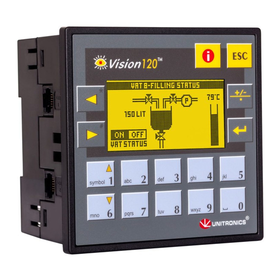
Chapter 1: Overview Introducing the Vision120 OPLC™ The palm-sized Vision120 OPLC™ is a member of the Vision OPLC series, programmable logic controllers that comprise an integral graphic operating panel. The Vision120 offers an on-board I/O configuration that varies according to model. Plug-in I/O Expansion Modules can also be easily integrated to greatly extend the system’s control capacity. -
Page 10: Technical Description
Vision120 OPLC™ User Guide Technical Description The Vision120 OPLC (V120) • Dimensions: 96 x 96 x 64mm (3.78” x 3.78” x 2.52”). • Mounting: either panel or DIN rail mountable. • Power supply: 12 or 24VDC. • Real-time clock (RTC): enables time and date controlled functions. •... - Page 11 Chapter 1: Overview • Build the PLC application using click-and-drop Ladder elements and functions. • Create a modular program, comprised of separate subroutines that can be called into the PLC application at any time. HMI Application The HMI application customizes the operator interface. Use it to: •...
-
Page 12: Safety Guidelines
Vision120 OPLC™ User Guide Data Type Symbol Data Type Symbol System Bits: System Long Integers: 64, 32 bit System Integers: System Double Word: 512, 16 bit 64, 32 bit Vision controllers also contain Data Tables, which may be used to store data or contain pre- programmed recipe parameters. -
Page 13: Chapter 2: Mounting
Chapter 2: Mounting The controller can be either panel-mounted or snap-mounted to a DIN rail. Before You Begin Before you begin installation procedures, check the contents of the controller kit. Standard kits contain the controller, green plastic plug-in connectors, and 2 black plastic mounting brackets, each with a screw inserted for panel mounting. -
Page 14: Safety And Environmental Guidelines
Vision120 OPLC™ User Guide Safety and Environmental Guidelines • Do not install in areas with: excessive or conductive dust, corrosive or flammable gas, moisture or rain, excessive heat, regular impact shocks or excessive vibration. • Do not place in water or let water leak onto the controller. •... -
Page 15: Figure 3. Panel Mounting The Controller
Chapter 2: Mounting Figure 3. Panel Mounting the Controller When properly mounted, the controller is squarely situated in the panel cut-out as shown in Figure 4. Figure 4. Panel Mounted... -
Page 16: Din Rail Mounting
Vision120 OPLC™ User Guide DIN Rail Mounting Snap the controller onto the DIN rail as shown in Figure 5. Figure 5. Snapping the Controller on to the DIN Rail When properly mounted, the controller is squarely situated on the DIN rail as shown in Figure 6. -
Page 17: Chapter 3: Power Supply
Chapter 3: Power Supply Power Supply The controller requires an external 12 or 24VDC power supply. The permissible input voltage range is listed in the technical specifications sheet supplied with the controller. You must use an external circuit protection device as shown in Figure 7, page 14. Safety Considerations •... -
Page 18: Figure 7. Power Supply Wiring
Vision120 OPLC™ User Guide We recommend that you use crimp terminals for wiring; use 26-14 AWG wire for all wiring purposes. Strip the wire to a length of 7±0.5 mm (0.250–0.300 inches). Unscrew the terminal to its widest position before inserting a wire. Insert the wire completely into the terminal to ensure a proper connection according to the figure below. -
Page 19: Chapter 4: I/Os
Chapter 4: I/Os The controller offers an: • On-board I/O Configuration Each model offers a different I/O configuration. • I/O Expansion Port Via an adapter, you can connect a broad variety of I/O modules to the controller’s I/O expansion port. Wiring Considerations •... -
Page 20: I/O Connections
Vision120 OPLC™ User Guide I/O Connections Strip the wire to a length of 7±0.5mm (0.250–0.300 inches). Unscrew the terminal to its widest position before inserting a wire. Insert the wire completely into the terminal to ensure a proper connection. Tighten enough to keep the wire from pulling free. Wire Size and Specifications •... -
Page 21: Digital Outputs
Chapter 4: I/Os Digital Outputs Each controller contains either relay or transistor outputs. The digital output value is placed in operand “O” when you write your program. The power supply for transistor outputs requires an external circuit protection device. See the technical specifications supplied with the controller. -
Page 22: Figure 9. Integrating I/O Expansion Modules
Vision120 OPLC™ User Guide EX-A1 Earth expansion port Figure 9. Integrating I/O Expansion Modules Exact instructions are provided with the adapter and I/O Expansion Modules. • Turn off the power before installing I/O expansion modules. -
Page 23: Chapter 5: Communications
Chapter 5: Communications This chapter contains guidelines for communications connections. The controller has 2 RJ-11-type serial communication ports. Each port can be adapted to either the RS232 or RS485 standard, via jumpers located within the controller and the appropriate VisiLogic program settings. -
Page 24: Downloading Your Program
Vision120 OPLC™ User Guide Table 1: RS232: Pinout Diagram Pin Number RS232: Function DTR signal 0V reference TxD signal RxD signal Pin #1 0V reference DSR signal Note that standard programming cables do not provide connection points for pins 1 and 6. In addition, note that when a port is adapted to RS485, Pin 1 (DTR) is used for signal A, and Pin 6 (DSR) signal is used for signal B as shown in Table 2. -
Page 25: Rs485
Chapter 5: Communications RS485 Use RS485 to create a multi-drop network containing up to 32 devices. Table 2: RS485: Pinout Diagram Pin Number Function A signal (+) (RS232 signal) (RS232 signal) (RS232 signal) Pin #1 (RS232 signal) B signal (-) Note that when a port is set to RS485, both RS232 and RS485 can be used simultaneously if flow control signals DTR and DSR are not used. -
Page 26: Rs485 Network Termination Settings
Vision120 OPLC™ User Guide RS485 Network Termination Settings The jumper settings shown in Table 4 determine whether the controller can function as an end device in a RS485 network. Note that the factory default setting is ON. If the OPLC is not a network end device, set both jumpers to OFF. -
Page 27: Opening The Controller
Chapter 5: Communications Opening the Controller • Before opening the controller, touch a grounded object to discharge any electrostatic charge. • Avoid touching the PCB board directly by holding the PCB board by its connectors. Turn power off before opening the controller. Locate the 4 slots on the sides of the controller. -
Page 28: Figure 13. Rs232/Rs485 Jumpers, Factory Default Settings
Vision120 OPLC™ User Guide Locate the jumpers shown in Figure 13, then change the jumper settings as Figure 13. RS232/RS485 Jumpers, required. Factory Default Settings Gently replace the PCB board as shown in Figure 14. Make certain that the pins fit correctly into their matching receptacle. -
Page 29: Canbus
63 controllers. This is sometimes called a multi-master network. In such a network, CANbus enables inter-PLC data exchange. Unitronics’ CANbus control network is run by a separate isolated power supply that is not part of the network power supply. CANbus Specifications Power Requirements: 24VDC (±4%), 40mA max. -
Page 30: Figure 15. Canbus Wiring Diagram
Vision120 OPLC™ User Guide 24V Power Supply Circuit protection device terminating resistor terminating resistor Figure 15. CANbus Wiring Diagram... -
Page 31: Chapter 6: Information Mode
Chapter 6: Information Mode Information Mode is a utility that is embedded in the operating system of the controller. Via Information Mode, you can view data on the LCD screen, use the controller’s keyboard to directly edit data, and perform certain actions such as resetting the controller. You can enter Information Mode at any time without regard to what is currently displayed on the LCD screen Viewing data does not affect the controller’s program. -
Page 32: Figure 16. Navigating Information Mode
Vision120 OPLC™ User Guide Figure 16. Navigating Information Mode Table 5 shows the categories of information that can be accessed in this mode. -
Page 33: Table 5: Information Mode
Chapter 6: Information Mode Table 5: Information Mode Category Subject Possible Actions Data Types • View input status. Inputs • Force input status to 1 (FR1) or 0 (FR0). Forced values stay in effect until Normal mode (NRM) is selected, or until the controller is initialized or reset. - Page 34 Vision120 OPLC™ User Guide Category Subject Possible Actions System • Check the controller’s model number Model & O/S Ver and operating system version. • Check whether the controller is in Run or Stop mode. Working Mode • Check whether the controller is in Run or Stop mode.
- Page 35 Chapter 6: Information Mode Category Subject Possible Actions Function Block FBs in use • Shows a list of all function blocks that have been downloaded into the controller. Both the FB name and its version are displayed. Password • Set a New Password Hardware •...
-
Page 36: Figure 17. Information Mode: Hardware Configuration
Vision120 OPLC™ User Guide Identical letters signify identical I/O Expansion Module types. X--no I/O Expansion Module installed Shows that an I/O on Expansion Module # 5 is short-circuited Shows that I/Os on Snap-in Module are not short-circuited Figure 17. Information Mode: Hardware Configuration... -
Page 37: Appendix A: System Data Types
Appendix A: System Data Types The Vision OPLC operating system – user program interface includes System Bits (SB), System Integers (SI), System Long Integers (SL), and System Double Words (SDW) listed in the tables below. Specific data types are linked to fixed parameters and are read-only by the user program, such as SB 2 Power-up bit. -
Page 38: Table 7: Keypad System Bit Functions
Vision120 OPLC™ User Guide Table 7: Keypad System Bit Functions System Bit (SB) Keypad Key System Bit (SB) Keypad Key SB 40 SB 49 SB 41 SB 50 SB 42 SB 51 SB 43 SB 52 SB 44 SB 53 SB 45 SB 57 SB 46... -
Page 39: Table 8: System Integer Functions
Appendix A: System Data Types Table 8: System Integer Functions System Integer Function Scan Time (mSec) Current key pressed LCD contrast Unit ID LCD Backlight intensity Current second—according to RTC Current time—according to RTC Current date—according to RTC Current year— according to RTC Current day—... -
Page 40: Table 9: System Long Integer Functions
Vision120 OPLC™ User Guide Table 9: System Long Integer Functions System Long Integer Function Divide Remainder (signed divide function) Table 10: System Double Word Functions System Double Word Function 10mS counter Divide Remainder (unsigned divide function) Output(s) short circuit bitmap... -
Page 41: Appendix B: New Plc Users
Appendix B: New PLC Users PLCs, or programmable logic controllers, are electronic control systems based on microprocessors. A PLC performs control functions in accordance with its software program of external automated equipment. Parts of a PLC Operating Panel The operating panel provides what is called the HMI, or Human Machine Interface, between you and the PLC. -
Page 42: Figure 18. Plc Scan
Vision120 OPLC™ User Guide Reads data from inputs Processes data according to program Sends data to outputs Figure 18. PLC Scan First, the input data is read at the beginning of each scan. The data has two sources: the PLC’s physical inputs, and data that are entered via the PLC’s keypad. Next, the program is executed. - Page 43 Figures and Tables Figures Figure 1. The Vision120 OPLC™ System ..............5 Figure 2. Connectors and Mounting Brackets ............9 Figure 3. Panel Mounting the Controller ..............11 Figure 4. Panel Mounted..................11 Figure 5. Snapping the Controller on to the DIN Rail ..........12 Figure 6.
- Page 44 Vision120 OPLC™ User Guide Notes...
- Page 46 Vision120 OPLC™ User Guide Notes...
Need help?
Do you have a question about the Vision 120 OPLC and is the answer not in the manual?
Questions and answers