Sign In
Upload
Manuals
Brands
Unitronics Manuals
Control Panel
Vision 120 OPLC
Unitronics Vision 120 OPLC controller Manuals
Manuals and User Guides for Unitronics Vision 120 OPLC controller. We have
1
Unitronics Vision 120 OPLC controller manual available for free PDF download: User Manual
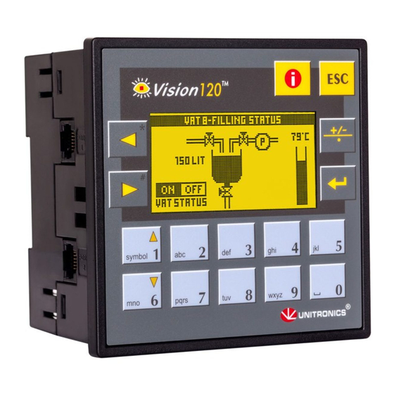
Unitronics Vision 120 OPLC User Manual (46 pages)
Graphic operator panel & programmable logic controller
Brand:
Unitronics
| Category:
Control Panel
| Size: 0 MB
Table of Contents
Table of Contents
6
Preface
7
Guidelines for User Safety and Equipment Protection
7
Warnings
8
Chapter 1: Overview
9
Introducing the Vision120 OPLC
9
Figure 1. the Vision120 OPLC™ System
9
Technical Description
10
Safety Guidelines
12
Chapter 2: Mounting
13
Before You Begin
13
Figure 2. Connectors and Mounting Brackets
13
Safety and Environmental Guidelines
14
Panel Mounting
14
Figure 3. Panel Mounting the Controller
15
Figure 4. Panel Mounted
15
DIN Rail Mounting
16
Figure 5. Snapping the Controller on to the DIN Rail
16
Figure 6. Proper DIN Rail Position
16
Chapter 3: Power Supply
17
Power Supply
17
Safety Considerations
17
Wiring the Power Supply
17
Figure 7. Power Supply Wiring
18
Chapter 4: I/Os
19
Wiring Considerations
19
On-Board I/Os
19
I/O Connectors
19
I/O Connections
20
Wire Size and Specifications
20
I/O Options: According to Model
20
Digital Inputs
20
High-Speed Counter/Shaft-Encoder
20
Analog I/Os
20
Digital Outputs
21
Installing I/O Expansion Modules
21
Figure 8. Increase the Contact Life Span
21
Figure 9. Integrating I/O Expansion Modules
22
Chapter 5: Communications
23
Rs232
23
Downloading Your Program
24
Connecting the Controller to the PC
24
Figure 10. Connecting the PC to the Controller
24
Table 1: RS232: Pinout
24
Rs485
25
Table 2: RS485: Pinout
25
RS485 Network Termination Settings
26
RS232/RS485 Jumper Settings
26
Table 3: RS232/RS485 Jumper Settings
26
Table 4: RS485 Termination Settings
26
Opening the Controller
27
Figure 11. Opening the Controller
27
Figure 12. Removing the Top PCB Board
27
Figure 13. RS232/RS485 Jumpers, Factory Default Settings
28
Figure 14. Replacing the Board
28
Canbus
29
Canbus Specifications
29
Wiring Considerations
29
Figure 15. Canbus Wiring Diagram
30
Chapter 6: Information Mode
31
Using Information Mode
31
Figure 16. Navigating Information Mode
32
Table 5: Information Mode
33
Figure 17. Information Mode: Hardware Configuration
36
Appendix A: System Data Types
37
Table 6: System Bit Functions
37
Table 7: Keypad System Bit Functions
38
Table 8: System Integer Functions
39
Table 9: System Long Integer Functions
40
Table 10: System Double Word Functions
40
Appendix B: New PLC Users
41
Figure 18. PLC Scan
42
Figures and Tables Figures
43
Advertisement
Advertisement
Related Products
Unitronics Vision OPLC V130-33-B1
Unitronics Vision OPLC V130-J-B1
Unitronics Vision OPLC V350-35-B1
Unitronics Vision OPLC V350-J-B1
Unitronics Vision OPLC V430-J-B1
Unitronics Vision OPLCV350-J-T2
Unitronics Vision 230
Unitronics Vision 260
Unitronics Vision 280
Unitronics Vision 290
Unitronics Categories
Controller
I/O Systems
Control Unit
Network Router
Adapter
More Unitronics Manuals
Login
Sign In
OR
Sign in with Facebook
Sign in with Google
Upload manual
Upload from disk
Upload from URL