Table of Contents
Advertisement
Quick Links
Advertisement
Table of Contents

Related Manuals for CAI 600-NDIR


Summary of Contents for CAI 600-NDIR
- Page 2 Section 1 Model 601/601P/602/602P/603 NDIR Analyzer Safety Alert Temperature Hazard Electrical Shock Hazard Caution or Warning Caution or Warning Caution or Warning Safety Information in this Manual Note, caution and warning symbols appear on the instrument and throughout this manual to draw your attention to important operational and safety information.
- Page 3 Section 1 Model 601/601P/602/602P/603 NDIR Analyzer The 600 series NDIR instruments meet or exceed the following directives and standards. Application of Council Directive(s): Electrical Safety: Low Voltage Directive 73/23/EEC Electromagnetic Compatibility: EMC Directive 89/336/EEC Standard(s) to which Conformity is Declared: Electrical Safety: Standard for Electrical Equipment for Measurement, Control, and Laboratory Use [EN 61010-1:2001 (2nd Edition)
- Page 4 Section 1 Model 601/601P/602/602P/603 NDIR Analyzer 600 NDIR Quick Start Guide Plug in the analyzer and turn the power on. Connect the appropriate gas lines and vents to the analyzer. Allow the analyzer to stabilize for at least one (1) hour. During the analyzer’s stabilization period, setup the analyzer to the desired configuration.
-
Page 5: Table Of Contents
Section 1 Model 601/601P/602/602P/603 NDIR Analyzer TABLE OF CONTENTS Introduction........................14 1.1. Overview........................14 1.2. Unpacking Instructions .....................14 1.3. Reporting Damage ....................14 1.4. Contact Information ....................14 1.5. Warranty Certificate....................15 1.6. Possible Explosion Hazard..................16 1.7. Electrical Shock Hazard ...................16 1.8. Plug Removal ......................16 Features..........................17 2.1. - Page 6 Section 1 Model 601/601P/602/602P/603 NDIR Analyzer Basic Operation ......................25 4.1. Display........................25 4.2. Menu Trees ......................26 4.3. Keyboard ........................29 4.3.1. Operation with the Cursor Keys and the Enter Key ........29 4.3.2. Operation with the Function Keys..............29 4.3.3. Read/Change Parameters ................29 Operating Structure.......................30 5.1.
- Page 7 Section 1 Model 601/601P/602/602P/603 NDIR Analyzer 7.5.2. Calibration Settings..................41 7.5.3. F1 Times......................41 7.5.4. F2 Measuring Deviations ................41 7.5.5. F3 Deviations....................41 7.5.6. F3 Range Limits...................41 7.5.7. F1 Range 1-4 (Change Upper Range Limits) ..........42 7.5.8. F2 Change Auto Range Limits..............42 7.5.9. F4 Alarms ....................43 7.5.10.
- Page 8 Section 1 Model 601/601P/602/602P/603 NDIR Analyzer 8.4. Internal Component Locations..................56 8.5. Main Electronics Board (Potentiometers) ..............57 8.6. NDIR Detector Assembly..................58 Operation........................59 9.1. External Wiring ......................59 9.2. External Piping ......................59 9.3. Operation & Calibration ....................59 9.3.1. Power On:....................59 9.3.2. Zero/San Adjustment: ..................59 9.3.3.
- Page 9 Section 1 Model 601/601P/602/602P/603 NDIR Analyzer 11.7.1. Problem: ......................71 11.7.2. Symptom:.....................71 11.7.3. Check and or replace:..................71 11.8. Check and Repair Tubing Trouble................71 11.8.1. Problem: ......................71 11.8.2. Symptom......................71 11.8.3. Check and/or replace:..................71 11.9. Check and Repair Amplifier Circuit................72 12. Communication Master Computer / Analyzer (AK Protocol) ........73 12.1.
- Page 10 Section 1 Model 601/601P/602/602P/603 NDIR Analyzer 12.4.18. AKAL: Deviations from calibration ..............79 12.4.19. ASYZ: Respond System Time..............79 12.4.20. AT90: Respond Lowpass filter time.............79 12.4.21. ADAL: Diagnostic alarm limits..............79 12.4.22. ATCP: Query TCP/IP settings ..............79 12.4.23. AVER: Query Software version ..............80 12.4.24.
- Page 11 Section 1 Model 601/601P/602/602P/603 NDIR Analyzer 12.6.8. ESYZ: Set System Time ................84 12.6.9. ET90: Set Lowpass Filter Time ..............84 12.6.10. EDAL: Diagnostic alarm limits ..............84 12.6.11. ETCP: Set TCP/IP Parameters..............84 12.6.12. EH2O Set H O correction parameters ............84 12.6.13. ECO2 Set CO correction parameters ............84 12.6.14.
- Page 12 Section 1 Model 601/601P/602/602P/603 NDIR Analyzer Table of Figures Figure 2-1 Single NDIR Analyzer....................18 Figure 2-2 Detector Output Signal ....................19 Figure 2-3 Absorption Characteristic of Detector................19 Figure 2-4 Block Diagram .......................20 Figure 3-1 AC Power Switch, Connector, and Fuse...............22 Figure 3-2 EMI Suppressor...............Error! Bookmark not defined.
- Page 13 Section 1 Model 601/601P/602/602P/603 NDIR Analyzer Figure 7-31 System Setup Screen....................46 Figure 7-32 Clock and Timing Setup Screen ..................46 Figure 7-33 Clock set screen ......................46 Figure 7-34 Set Auto Cal Timing.....................47 Figure 7-35 Set Auto Cal Ranges ....................47 Figure 7-36 F4 Toggles Auto Cal ON of OFF .................47 Figure 7-37 TCP/IP Address......................48 Figure 7-38 Output Assignments ....................48 Figure 7-39 Output Ranges ......................48...
-
Page 14: Introduction
Section 1 Model 601/601P/602/602P/603 NDIR Analyzer Introduction 1.1. Overview Congratulations and thank you! You have just purchased one of the most reliable gas analyzers in the world. Before using the analyzer, please familiarize yourself with its operation by reading this manual. If you have any questions, please do not hesitate to call California Analytical Instruments for assistance. -
Page 15: Warranty Certificate
(ii) to refund the purchase price. The exceptions and conditions mentioned above are as follows: a. components or accessories manufactured by CAI that by their nature are not intended to or will not function for one year are warranted only to give reasonable service for a reasonable time. What constitutes reasonable time and reasonable services shall be determined solely by CAl. -
Page 16: Possible Explosion Hazard
Section 1 Model 601/601P/602/602P/603 NDIR Analyzer 1.6. Proper Operation Personnel should be trained in the proper operation of this equipment before attempting to operate the equipment. 1.7. Possible Explosion Hazard Do not apply power to the analyzer or attempt to energize the analyzer until determining the analyzer environment to be non-hazardous. -
Page 17: Features
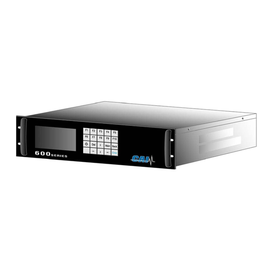
Section 2 Model 601/601P/602/602P/603 NDIR Analyzer Features 2.1. Description The Model 600 series of NDIR analyzers incorporate a single-beam photometric system and a detector with a microflow sensor assuring high reliability, sensitivity, accuracy, and stability. The microflow detector is a sealed unit filled with the same gas as the component of interest (CO, CO , and CH ). -
Page 18: Infrared Gas Analyzers
Section 2 Model 601/601P/602/602P/603 NDIR Analyzer 2.4. Infrared Gas Analyzers The infrared gas analyzer measures gas concentration based on the principle that each type of gas component shows a unique absorption line spectrum in the infrared region. The instrument consists of an infrared light source, a chopper, a measuring cell, and a detector filled with a gas mixture containing the gas component to be measured. -
Page 19: Interference Gases
Section 2 Model 601/601P/602/602P/603 NDIR Analyzer Output Zero gas Span gas Zero gas Span gas = K (Constant) Concentration Figure 2-2 Detector Output Signal Figure 2-3 Absorption Characteristic of Detector 2.5. Interference Gases Whenever a sample gas contains a gas component that has an absorption spectrum that overlaps the spectrum of the gas to be measured, that gas is commonly referred to as an interference gas. -
Page 20: Electronics
Section 2 Model 601/601P/602/602P/603 NDIR Analyzer 2.6. Electronics The sinusoidal output signal of the detector’s microflow sensor is transmitted to the AC amplifiers on the main circuit board. The signal frequency is related to the rate of the beam- interrupting chopper blade. The signal amplitude is related to the measured gas concentrations in the sample cell. -
Page 21: Model 600 Ndir Specifications
Section 2 Model 601/601P/602/602P/603 NDIR Analyzer 2.7. Model 600 NDIR Specifications Non-Dispersive Infrared (NDIR) IR ANALYSIS METHOD NDIR COMPONENTS CO /CO / CH DETECTOR TYPE Microflow RANGE RATIO 50:1 (Highest Range/50 = Lowest Range) RESPONSE TIME (IR) T90 < 2 Seconds to 60 Seconds Adjustable (Depending on configuration) Stainless Steel with Replaceable Gold Cell Liner IR SAMPLE CELL Displays Five Significant Digits... -
Page 22: Installation
Section 3 Model 601/601P/602/602P/603 NDIR Analyzer Installation 3.1. General The design of this instrument is for industrial applications. These installation instructions are for a typical site. Direct any questions regarding specific installation situations to Technical Service of California Analytical Instruments, Inc. 3.2. -
Page 23: Analog Output Connections
Section 3 Model 601/601P/602/602P/603 NDIR Analyzer Replace fuses with recommended fuse size indicated on rear panel of instrument. Replacement with any other size fuse may cause damage to the instrument and possible injury to operating personnel. 3.4. Analog Output Connections (Appendix) See Appendix for connector pinouts located on the analyzer rear panel. -
Page 24: Gas Handling Equipment
Section 3 Model 601/601P/602/602P/603 NDIR Analyzer 3.6. Gas Handling Equipment Pressure regulators for zero gas (Air or N2), and span gas cylinders. Corrosive resistant gas tubing. 3.7. Gas Connections The tubing from the sampling system to the gas analyzer should be made from corrosive- resistant material such as Teflon or stainless steel. -
Page 25: Basic Operation
Section 4 Model 601/601P/602/602P/603 NDIR Analyzer Basic Operation The operation of the digital microprocessor conforms to the guidelines of the AK committee, originally developed in the German automotive industry. Via the serial port of the MSR-Card, the analyzer can be remote-controlled by a master computer. The serial communication fully corresponds to the specifications of the AK protocol. -
Page 26: Menu Trees
Section 4 Model 601/601P/602/602P/603 NDIR Analyzer 4.1. Menu Trees Model 601 Menu Tree Main Menu (All access) F1 Measurement F2 Purge Analyzer F3 Diagnostics F4 Calibration F5 Setup F6 Remote/Manual F7 Stand by Measurement Toggles pump on Sets analyzer in purge mode Purge Analyzer Diagnostics Flow 1... - Page 27 Section 4 Model 601/601P/602/602P/603 NDIR Analyzer Main Menu (All access) F1 Measurement F2 Purge Analyzer F3 Diagnostics F4 Calibration F5 Setup F6 Remote/Manual F7 Stand by (F4) Calibration F1 Auto calibration F2 Manual calibration F3 Display deviations F4 Check calibration F5 Reset calibration values Auto calibration Flow zero gas...
- Page 28 Section 4 Model 601/601P/602/602P/603 NDIR Analyzer Main Menu (All access) F1 Measurement F2 Purge Analyzer F3 Diagnostics F4 Calibration F5 Setup Span gas concentrations F6 Remote/Manual F7 Stand by Calibration settings F1 Times F2 Measuring deviations % Setup F3 Deviation % (All access) F4 Calibration via values F5 Calibration via pump...
-
Page 29: Keyboard
Section 4 Model 601/601P/602/602P/603 NDIR Analyzer 4.2. Keyboard Combined control / numeral keys To the main menu Display lighting Cancel, back to on / off Main Back the last menu Delete key End input, open selected field for input Switch-over of the keyboard Arrow keys for selecting the functions and numeral / control keys editing fields and for scrolling possible input values... -
Page 30: Operating Structure
A password can be assigned to each operating level. Only the system user, who normally has the highest operating priority, can assign the password. At the factory, the default passwords for the CAI analyzers are set as follows: User: Advanced user:... -
Page 31: The Main Menu
Section 5 Model 601/601P/602/602P/603 NDIR Analyzer 5.1. The Main Menu Upon power up, the CAI logo is first displayed and then the main menu appears as below: NOTE: Access Level Indication Figure 5-1 Main Menu on Power Up Screen NOTE: F6 is not available because, on initial start up, the analyzer reverts to ONLY Level 1 access. -
Page 32: Menu Structure
Section 6 Model 601/601P/602/602P/603 NDIR Analyzer Menu Structure There are four operating levels based on the level of your password. This section shows the access rights of the single levels. 6.1. User Functions (Level 1) Main Menu Setup Menu Password Menu Measurements Password Enter password... -
Page 33: Main Menu Function Descriptions
Section 7 Model 601/601P/602/602P/603 NDIR Analyzer Main Menu Function Descriptions 7.1. F1 Measurements Figure 7-1 Main Menu Screen 7.1.1. F1 Measurement The measurements screen is activated by pressing F1 on the Main Menu screen. The concentration is displayed in actual engineering units. Figure 7-2 Measurements Screen California Analytical Model 600_NDIR_Series_v10.0 CE Operators Manual... -
Page 34: Range Select
Section 7 Model 601/601P/602/602P/603 NDIR Analyzer 7.1.2. Range Select With the arrow keys, the ranges 1 to 4 can be selected and locked in which will disable the auto range capability. Continue pressing the arrow keys will recycle the analyzer back to auto range. -
Page 35: F2 Purge Analyzer
Section 7 Model 601/601P/602/602P/603 NDIR Analyzer 7.2. F2 Purge Analyzer Figure 7-5 Main Menu (User Level 4) Figure 7-6 Purge Screen F2 from the Main Menu activates the Purge (analyzer) function if equipped. 7.3. F3 Diagnostics F3 from the Main Menu activates the Diagnostics function. F3 brings up the two diagnostics screens. -
Page 36: F4 Calibrations
Section 7 Model 601/601P/602/602P/603 NDIR Analyzer 7.4. F4 Calibrations F4 from the Main Menu activates the Calibrations screen. Calibrations may be automatic or manual. Deviations can also be displayed. Calibration values can be reset to default values and the range to be calibrated can be changed. Figure 7-8 Calibration Screen 7.4.1. -
Page 37: F2 Manual Calibration
Section 7 Model 601/601P/602/602P/603 NDIR Analyzer 7.4.2. F2 Manual Calibration From the Calibration screen, F2 starts manual calibration. If auto range is selected, calibration is not possible, and the appropriate range can be selected. Figure 7-10 Manual calibration In the manual calibrations menu, two options are possible: F1 Flow zero gas F2 Flow span gas Figure 7-11 Manual zero calibration... -
Page 38: Display Deviations - From Calibration Menu F3
Section 7 Model 601/601P/602/602P/603 NDIR Analyzer When zero or span gas is flowing, the measured value can be saved by pressing F1. If the screen is left by pressing the buttons ”Main” or ”Back”, the measured value is not saved. Solenoids are closed by pressing F2. -
Page 39: Absolute Span Gas Deviation
Section 7 Model 601/601P/602/602P/603 NDIR Analyzer 7.4.6. Absolute Span Gas Deviation Absolute span gas deviation is span gas bottle value minus span gas value calculated by the factory-polynomial related to the range limit of the calibrated range. 7.4.7. Relative Span Gas Deviation Relative span gas deviation is the actual deviation minus the deviation of the previous calibration related to the range limit of the calibrated range. -
Page 40: F5 Setup
Section 7 Model 601/601P/602/602P/603 NDIR Analyzer 7.5. F5 Setup From the Main Menu, F5 brings up the setup menu. Span gas concentrations, calibration settings, range limits, alarms, password, linearization, system and measure settings can be changed. The Setup menu begins as shown below. A description of each parameter is shown in the information box. -
Page 41: Calibration Settings
Section 7 Model 601/601P/602/602P/603 NDIR Analyzer 7.5.2. Calibration Settings Figure 7-19 Change Auto Calibration Settings In the calibration settings menu, times and, deviations can be changed. 7.5.3. F1 Times There are four times (in seconds) for auto calibration that can be changed. Purge, measuring, calibration and verifying time. -
Page 42: F1 Range 1-4 (Change Upper Range Limits)
Section 7 Model 601/601P/602/602P/603 NDIR Analyzer 7.5.7. F1 Range 1-4 (Change Upper Range Limits) In this menu, the upper range limits can be changed. The new settings are saved by pressing MAIN or BACK. The auto range limits are automatically adapted. This means that if the upper range limit of range 1 for example has reached 90% of the upper range limit in the auto range mode, it is switched automatically to the second range. -
Page 43: F4 Alarms
Section 7 Model 601/601P/602/602P/603 NDIR Analyzer 7.5.9. F4 Alarms Error reports are always displayed in the lowest line of the screen. There are two pressures, three temperatures, one concentration, and two voltages with alarm limits that can be defined. The user can define the range limits and, if exceeded, will display an error-message. -
Page 44: F1 Enter Password
Section 7 Model 601/601P/602/602P/603 NDIR Analyzer 7.5.11. F1 Enter Password To change access level, press F1. The following screen appears: Figure 7-26 Access Level Screen F1 to F4 selects an access level. Move the cursor to the access level to be modified. You must enter the correct password for the access level desired. -
Page 45: F6 Linearization
Section 7 Model 601/601P/602/602P/603 NDIR Analyzer 7.5.14. F6 Linearization Pressing F6 on the Setup screen brings up the Linearization screen. The analyzer can be linearized by a polynomial with 5 coefficients. By pressing F1, these 5 coefficients can be changed for each range. By pressing F2, the raw value can be displayed. This is the value before linearization and offset span correction. -
Page 46: F7 System Settings
Section 7 Model 601/601P/602/602P/603 NDIR Analyzer 7.6. F7 System Settings This screen allows all the system settings to be displayed and modified. Figure 7-31 System Setup Screen 7.6.1. F1 Real Time Clock This brings up the clock time set screen; auto cal and auto cal enable screens. Figure 7-32 Clock and Timing Setup Screen Figure 7-33 Clock set screen The current time may be set by using the cursor to highlight the entry and using the numeric... -
Page 47: Figure 7-34 Set Auto Cal Timing
Section 7 Model 601/601P/602/602P/603 NDIR Analyzer Figure 7-34 Set Auto Cal Timing Figure 7-35 Set Auto Cal Ranges Figure 7-36 F4 Toggles Auto Cal ON of OFF California Analytical Model 600_NDIR_Series_v10.0 CE Operators Manual Page 47 of 86... -
Page 48: System Setup F2 Displays Tcp/Ip Address
Section 7 Model 601/601P/602/602P/603 NDIR Analyzer 7.6.2. System Setup F2 Displays TCP/IP Address Figure 7-37 TCP/IP Address 7.6.3. Systems Setup F3 Displays Output Signal Assignments (Used to Adjust Analog Output Channels) Figure 7-38 Output Assignments 7.6.4. System Setup F4 Displays Output Ranges (Used to Adjust Scale of Analog Output Channels) Figure 7-39 Output Ranges California Analytical Model 600_NDIR_Series_v10.0 CE... -
Page 49: F5 Turns Status Line On Or Off
Section 7 Model 601/601P/602/602P/603 NDIR Analyzer 7.6.5. F5 Turns Status Line On or Off The status line displays the AK Protocol action on the top line of the display. Figure 7-40 Status line Figure 7-41Status line on/off 7.6.6. F8 Measure Settings This screen allows several of the system settings to be displayed and modified. -
Page 50: F2 Purge Time
Section 7 Model 601/601P/602/602P/603 NDIR Analyzer 7.6.8. F2 Purge Time F2 on the Menu Settings screen the sets the purge time before continuing with a zero or span calibration. Figure 7-44 Purge Time 7.6.9. F3 Set Temperature Compensation Figure 7-45 T-compensation 7.6.10. -
Page 51: F10 Displays The Current Analyzer And Software Versions
Section 7 Model 601/601P/602/602P/603 NDIR Analyzer Figure 7-47 Low pass filter time constant 7.6.12. F10 Displays the Current Analyzer and Software Versions This displays the analyzer’s information, including the factory recommended air and sample pressure settings. Figure 7-48 Analyzer Information Figure 7-49 Software Version 7.7. -
Page 52: F8 Standby
7.8. F8 Standby Figure 7-51 F7 Standby Main Menu (User Level 4) In Standby mode, pump is turned off and the solenoids are closed. The CAI logo is displayed. Figure 7-52 Standby Mode California Analytical Model 600_NDIR_Series_v10.0 CE Operators Manual... -
Page 53: Analyzer Components
Section 8 Model 601/601P/602/602P/603 NDIR Analyzer Analyzer Components 8.1. Rear Panel The following details the rear panel connections: Figure 32: Rear Panel Sample Gas Inlet: Feeds sample gas to the analyzer. ¼ Inch Tube. Sample Gas Bypass Outlet (Vent): Exhaust for sample. ¼ Inch Tube. TCP/IP Connection: Connect Network Connector. -
Page 54: Rear Panel Connectors
Section 8 Model 601/601P/602/602P/603 NDIR Analyzer 8.2. Rear Panel Connectors 28 Pin Auxiliary Connector 28 Pin Main Connector Assignments: Assignments: Main 1 Main 2 Main 3 601, 602, 603 Signal Signal Optional Optional Type Type Analog Analog Analog Analog Pin # Pin # Pin # Spare... -
Page 55: Digital Outputs
Section 8 Model 601/601P/602/602P/603 NDIR Analyzer 8.3. Digital Outputs 8.3.1. RS-232 (Standard 9 Pin DIN Connector) Function DCD Carrier Detect RxD Receive Data TxD Transmit Data DTR Data Terminal Ready Ground DSR Data Set Ready RTS Ready to Send CTS Clear to Send RI Ring Indicator 8.3.2. -
Page 56: Internal Component Locations
Section 8 Model 601/601P/602/602P/603 NDIR Analyzer 8.4. Internal Component Locations Figure 8-1 Internal components Signal conditioning PCB. NDIR detector. Sample cell. IR source and chopper motor assembly. DC power supply module. California Analytical Model 600_NDIR_Series_v10.0 CE Operators Manual Page 56 of 86... -
Page 57: Main Electronics Board (Potentiometers)
Section 8 Model 601/601P/602/602P/603 NDIR Analyzer 8.5. Main Electronics Board (Potentiometers) Figure 8-2 Main Electronic Board Potentiometers Detector voltage adjust Fine zero adjust Not used (Fully CW) Coarse zero adjust Span adjust NOTE: Potentiometers are clearly labeled on both sides of the Wave PCB. California Analytical Model 600_NDIR_Series_v10.0 CE Operators Manual Page 57 of 86... -
Page 58: Ndir Detector Assembly
Section 8 Model 601/601P/602/602P/603 NDIR Analyzer 8.6. NDIR Detector Assembly Figure 8-3 NDIR detector assembly Detector Assembly. Sample cell assembly. Light source and chopper motor assembly Sample inlet. Sample outlet. Temperature sensing element (to J2 of Wave PCB) California Analytical Model 600_NDIR_Series_v10.0 CE Operators Manual Page 58 of 86... -
Page 59: Operation
Section 9 Model 601/601P/602/602P/603 NDIR Analyzer Operation 9.1. External Wiring Make sure that the external wires have been connected as described in Section 3 Installation. 9.2. External Piping Review Section 3, 3.7 and 3.8 9.3. Operation & Calibration 9.3.1. Power On: Turn on the power switch (located on the rear panel). -
Page 60: Maintenance
Section 10 Model 601/601P/602/602P/603 NDIR Analyzer MAINTENANCE Warning All replacement parts must be as supplied and/or specified by California Analytical Instruments. Failure to used specified parts may reduce the safety features of the instrument or create a hazardous condition. 10.1. Zero and Span Calibration The zero and span levels should be checked and/or calibrated daily (or as often as required.) 10.2. -
Page 61: Figure 10-1 Optical Bench With Pipe Sample Cell
Section 10 Model 601/601P/602/602P/603 NDIR Analyzer Figure 10-1 Optical Bench with Pipe Sample Cell Item Description Item Description Screw (M4) Pipe sample cell Base O-Ring Infrared source unit Window Screw (M4) Detector Connector Bridge circuit board Sealed tubes Optical filter (if installed) Support Wave PCB Clamp... -
Page 62: Removal Of Pipe Cell
Section 10 Model 601/601P/602/602P/603 NDIR Analyzer 10.4. Removal of Pipe Cell (Figure 10-1) Discontinue the sample gas flow. When it contains harmful gas, purge the measuring cell sufficiently with zero gas. Turn the power switch to OFF. After loosening the retaining screws on the sides of the top cover, lift off top cover and locate the pipe cell. -
Page 63: Figure 10-2 Optical Bench With Block Sample Cell
Section 10 Model 601/601P/602/602P/603 NDIR Analyzer Figure 10-2 Optical Bench with Block Sample Cell Item Description Item Description Screw (M4) Block sample cell Base O-Ring Infrared source unit Window Screw (M4) Detector Screw (Round or Pan Head) Bridge circuit board Connector Optical filter (if installed) Sealed tubes... -
Page 64: Removal Of Block Cell
Section 10 Model 601/601P/602/602P/603 NDIR Analyzer 10.5. Removal of Block Cell (Figure 10-2) Discontinue the sample gas flow. When it contains harmful gas, purge the measuring cell sufficiently with zero gas. Turn the power switch to OFF. After loosening the retaining screws on the sides of the top cover, lift off the top cover and locate the block cell. -
Page 65: Figure 10-3 Optical Bench With Pipe And Block Type Sample Cells
Section 10 Model 601/601P/602/602P/603 NDIR Analyzer Figure 10-3 Optical Bench with Pipe and Block Type Sample Cells Item Description Item Description Screw (M4) Window Base Detector Infrared source unit Bridge circuit board Screw (M4) Optical filter (if installed Screw Screw (Flat Head) Connector Screw (Round or Flat Head) Sealed tubes... -
Page 66: Disassembly Of Combination Pipe & Block Type Cells
Section 10 Model 601/601P/602/602P/603 NDIR Analyzer 10.6. Disassembly of Combination Pipe & Block Type Cells (Figure 10-3) Discontinue the sample gas flow. When it contains harmful gas, purge the measuring cell sufficiently with zero gas. Turn OFF the power switch. After loosening the retaining screws on the sides of the top cover, lift off top cover and locate the block cell. - Page 67 Section 10 Model 601/601P/602/602P/603 NDIR Analyzer Alcohol or an alcohol-based glass cleaner is a suitable cleaning solution. A soft cloth or tissue that will not deposit lint should be used to clean the liner & windows. The pipe cells contain a reflective metal foil liner (not shown in Figure 10-3) to enhance the light energy through put in the cell.
-
Page 68: Adjustments Checks And Repairs
Section 11 Model 601/601P/602/602P/603 NDIR Analyzer ADJUSTMENTS CHECKS AND REPAIRS 11.1. Adjustment of Detector Voltage (NDIR’S only) Note: Adjustment is required if detector or NDIR amplifier board is replaced. Important: Turn RP2 to its maximum counter clockwise position before initial power up of a replacement detector or NDIR. -
Page 69: 11.4. Check And Repair Detector
Section 11 Model 601/601P/602/602P/603 NDIR Analyzer 11.4. Check and Repair Detector (No. 15 in Figure 10-1 and Figure 10-3, No. 14 in Figure 10-2) 11.4.1. Problem: Microflow sensor broken, bridge resistor defective or gas leak in detector. 11.4.2. Symptom: Zero adjustment impossible. 11.4.3. -
Page 70: 11.5. Check And Repair Infrared Light Source Unit
Section 11 Model 601/601P/602/602P/603 NDIR Analyzer 11.5. Check and Repair Infrared Light Source Unit (No. 5 in Figure 10-1) 11.5.1. Problem: A faulty infrared light source or a leaky gas seal. 11.5.2. Symptom: The unit reads off scale or the output is unstable. 11.5.3. -
Page 71: 11.7. Check And Repair Measuring Cell
Section 11 Model 601/601P/602/602P/603 NDIR Analyzer supplied to the connector on the power supply side. When power is supplied but the motor shaft does not rotate, check the shaft and blade sector for an obstruction. When the motor does not rotate, and there is no abnormal contact on the shaft or sector blade, the motor itself is defective. -
Page 72: 11.9. Check And Repair Amplifier Circuit
Section 11 Model 601/601P/602/602P/603 NDIR Analyzer 11.9. Check and Repair Amplifier Circuit Connect an oscilloscope across check terminals TP3 (signal) and TP9 (common) and observe the ac waveform. While zero gas is flowing, the amplitude of the waveform should be between 2.48Vpp and 2.8Vpp as shown below. This can be adjusted by following the procedure described under section 12.2 before making this adjustment it is recommended that a check for contamination in the cell and cell windows be done first, as this can lead to a reduction in amplitude of the ac... -
Page 73: Communication Master Computer / Analyzer (Ak Protocol)
Section 12 Model 601/601P/602/602P/603 NDIR Analyzer Communication Master Computer / Analyzer (AK Protocol) 12.1. Serial Interface and AK-Commands The serial interface enables remote control of the analyzer by a master computer. It is implemented as an RS232 V24 interface and meets all requirements of the AK protocol. A 9-pin male connector at the back of the unit is used to connect a master computer with the following pin assignment: Pin 2 = Rxd (receive) -
Page 74: Protocol Description
Section 12 Model 601/601P/602/602P/603 NDIR Analyzer 12.3. Protocol Description 12.3.1. Instruction command Character Explanation Byte ASCII code 02 Byte Don’t Care Any ASCII code Byte Function Code 1 Byte Function Code 2 AK instruction e.g.: ASTF Byte Function Code 3 Byte Function Code 4 Byte... -
Page 75: Data Description
Section 12 Model 601/601P/602/602P/603 NDIR Analyzer 12.3.3. Data Description Each command begins with STX (Start of Text) in the fist byte. The “don't care” byte can be any ASCII character. Generally, a blank or an underscore (_) is used for readability reasons. -
Page 76: Scan Commands
Section 12 Model 601/601P/602/602P/603 NDIR Analyzer 12.4. Scan Commands 12.4.1. AKON: Measured concentration value Command Response Description _AKON_K0 _AKON_s_z.z_y.y_x.x_w.w Measured concentration value of all channels is responded t = Timestamp (1/10 sec) _AKON_Km _AKON_s_z.z_t Measured concentration value of channel m is responded t = Timestamp (1/10 sec) 12.4.2. -
Page 77: Astz: Normal Device Status
Section 12 Model 601/601P/602/602P/603 NDIR Analyzer 12.4.6. ASTZ: Normal device status Command Response Description _ASTZ_K0 _ASTZ_s_K1_State1_State2_State3 Respond device status for all _K2_State1_State2_State3 channels _K3_State1_State2_State3 _ASTZ_Km _ASTZ_s_State1_State2_State3 Respond device status only for channel m Possible states: State 1 State 2 State 3 SREM: remote STBY: standby SARE: auto range on... -
Page 78: Atem: Temperatures
Section 12 Model 601/601P/602/602P/603 NDIR Analyzer 12.4.10. ATEM: Temperatures Command Response Description _ATEM_K0 _ATEM_s_z.z Device temperature degrees Celsius is responded _ATEM_Km _ATEM_s_z.z Detector temperature of channel m is returned in z.z 12.4.11. ADRU: Pressures/ Valve voltage Command Response Description _ADRU_K0 _ADRU_s_z.z Pressure in is responded _ADRU_Km... -
Page 79: Apar: Request Autocalibration Tolerance Values
Section 12 Model 601/601P/602/602P/603 NDIR Analyzer 12.4.17. APAR: Request Autocalibration tolerance values Command Response Description _APAR_Km_SATK _APAR_s_z.z_y.y_x.x_w.w Autocalibration tolerance value (%): z.z: Range 1 y.y: Range 2 x.x: Range 3 w.w: Range 4 12.4.18. AKAL: Deviations from calibration Command Response Description _AKAL_Km_ _AKAL_s_M1_z.z_y.y_x.x_w.w... -
Page 80: Aver: Query Software Version
Section 12 Model 601/601P/602/602P/603 NDIR Analyzer 12.4.23. AVER: Query Software version Command Response Description _AVER_K0 _AVER_s_3MAIN_z_3USER_y_OS z: Main version x.xxx.b_dd.mm.yyyy MSR_x y: User version x.xxx.b_dd.mm.yyyy x: OSMSR version x.xxx_dd.mm.yyyy 12.4.24. AH2O: QueryH O correction parameter Command Response Description _AH2O_Km _AH2O_s_z.z_y.y_x.x z.z: Dry –... -
Page 81: Control Commands
Section 12 Model 601/601P/602/602P/603 NDIR Analyzer 12.5. Control commands 12.5.1. SRES: Reset Command Response Description _SRES_K0 _SRES_s Reset 12.5.2. SPAU: Pause Command Response Description _SPAU_K0 _SPAU_s Pause mode 12.5.3. STBY: Standby Command Response Description _STBY_K0 _STBY_s Standby mode for all channels _STBY_Km _STBY_s Standby mode for channel m... -
Page 82: Sare: Auto Range On
Section 12 Model 601/601P/602/602P/603 NDIR Analyzer 12.5.9. SARE: Auto range on Command Response Description _SARE_K0 _SARE_s Set auto range on for all channels _SARE_Km _SARE_s Set auto range on for channel m 12.5.10. SARA: Auto range off Command Response Description _SARA_K0 _SARA_s Set auto range off for all channels... -
Page 83: Settings
NOTE: To change device identification, you must first rename the device to “RESET”. Now a name up to 40 characters can be given. NOTE: The device name must not have any blanks between characters, e.g. “CAI CLD” is not allowed. You can use underscores, e.g.. “CAI_CLD”. -
Page 84: Esyz: Set System Time
Section 12 Model 601/601P/602/602P/603 NDIR Analyzer 12.6.8. ESYZ: Set System Time Command Response Description _ESYZ_K0_yymmdd_hhmmss _ESYA_s Set system time: yymmdd: year, month, day (each 2 characters wide, no spaces) hhmmss: hour, minutes, seconds (each 2 characters, no spaces) 12.6.9. ET90: Set Lowpass Filter Time Command Response Description... -
Page 85: Eudp Set Udp Data Streaming Parameters
Section 12 Model 601/601P/602/602P/603 NDIR Analyzer 12.6.14. EUDP Set UDP Data streaming parameters Command Response Description _EUDP_K0_<UDPPort>_<DataFrequeny>_[<Mo _EUDP_s Configure an UDP channel for de>]_[<UDP_IP>] data streaming of the measuring values via Ethernet UDP. Port: port for open the UDP connection DataFrequency: Frequency for transmit the data in Hz Mode: A: ASCII Mode (optional) -
Page 86: Appendix
Section 12 Model 601/601P/602/602P/603 NDIR Analyzer Appendix Electrical Block Diagram California Analytical Model 600_NDIR_Series_v10.0 CE Operators Manual Page 86 of 86...
Need help?
Do you have a question about the 600-NDIR and is the answer not in the manual?
Questions and answers