Table of Contents
Advertisement
Quick Links
Advertisement
Table of Contents

Related Manuals for CAI 700 Series


Summary of Contents for CAI 700 Series
- Page 1 700 NDIR Analyzer 6-20-2017...
-
Page 2: Table Of Contents
700 NDIR Analyzer 6-20-2017 Table of Contents Introduction ........................5 Operating Principle ......................7 Analyzer Specifications ....................8 Installation ........................9 Safety Information ......................9 Startup and Shutdown ....................19 Using the Keypad ......................21 Menu Flow Chart ......................23 Main Menu ........................ - Page 3 700 NDIR Analyzer 6-20-2017 Range Setup ........................ 80 Range Limits ..........................81 Auto Range On/Off ........................83 AutoRange Switch Points ......................84 Diagnostics ......................... 85 Diagnostic Values ........................86 Raw Values Display ........................89 I/O Status ............................ 91 Analyzer Digital Outputs ......................92 Analyzer Digital Inputs ......................
- Page 4 700 NDIR Analyzer 6-20-2017 AK Protocol ......................146 Instruction Command ....................... 148 Acknowledgement Command ....................149 Error Handling ......................... 150 General AK Requirements ....................... 151 Scan Commands ........................153 Control Commands ........................164 Configuration Commands ......................168 Modbus Protocol ......................174 MBAP Description ........................
-
Page 5: Introduction
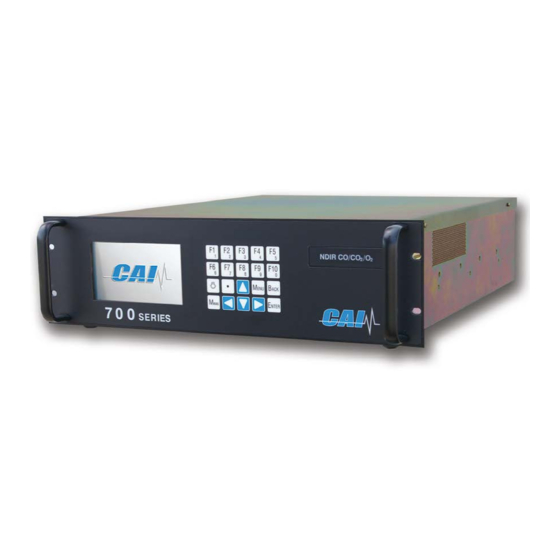
6-20-2017 Introduction PRELIMINARY Thank you for purchasing the CAI 700 NDIR CO/CO Analyzer. Before using the analyzer, please familiarize yourself with its operation by reading this manual. If you have any questions, please do not hesitate to call California Analytical Instruments Technical Support for assistance. - Page 6 700 NDIR Analyzer 6-20-2017 Multiple channels – up to three NDIR channels or two NDIR channels plus oxygen Auto calibration and ranging Fast response time Temperature and pressure compensation Comprehensive diagnostics CE Mark and ETL listed – conforms to UL STD 61010-1, certified to CAN/CSA C22.2 STD No.
-
Page 7: Operating Principle
700 NDIR Analyzer 6-20-2017 Operating Principle The CAI 700 NDIR/O analyzer is based on the infrared absorption characteristics of gases. Using a single infrared beam to measure gas concentrations, this analyzer delivers highly stable and reliable results. A single infrared light beam is modulated by a chopper system and passed through a sample cell of predetermined length containing the gas sample to be analyzed. -
Page 8: Analyzer Specifications
700 NDIR Analyzer 6-20-2017 Analyzer Specifications Specifications are subject to change without notice. IR Analysis Method: Non-dispersive infrared (NDIR) NDIR Components: CO, CO , CH , SO , NO Detector Type: Microflow NDIR Ranges*: From 0-50 ppm up to 0-100% *SO , 0-1% up to 0-20%, and CH 1,000 ppm up to 0-100% Range Ratio: 10:1... -
Page 9: Installation
700 NDIR Analyzer 6-20-2017 Installation Safety Information Safety Alert Temperature Hazard Electrical Shock Hazard Caution or Warning Caution or Warning Caution or Warning Note, Caution and Warning symbols appear on the instrument and in this manual to draw your attention to important operational and safety information. A “NOTE”... - Page 10 700 NDIR Analyzer 6-20-2017 symbol (a lightning bolt in a triangle) precedes an electrical shock hazard CAUTION or WARNING statement. Some or all of the above symbols may appear in this manual or on the equipment. This manual should be consulted whenever one of these symbols is encountered on the equipment.
- Page 11 The shipping container and packaging are specially designed to protect the analyzer in transport. If you ever need to return the analyzer to CAI for repair or any other reason, the original shipping container and packaging should be used.
- Page 12 5. The instrument is designed for rack mounting. Optional rack-mount slides are available. 6. Do not install the CAI 700 NDIR/O analyzer near equipment that emits electromagnetic interference (EMI). NOTE: A front and rear supporting brace or equivalent is required if the optional rack mount slides were not purchased.
- Page 13 700 NDIR Analyzer 6-20-2017 Rear Panel The rear panel includes the following: 1. TCP/IP connection to connect network connector. 2. Sample Gas inlet for introducing sample gas into the analyzer (¼-inch tube). 3. Sample Gas outlet (vent) for exhaust of sample gas (¼-inch tube). 4.
- Page 14 700 NDIR Analyzer 6-20-2017 Electrical All wiring is connected at the rear of the analyzer. The AC power cord is connected to the power entry as shown below: Fuse Panel Power ON/OFF Switch Power Entry AC Power Switch, Connector and Fuse. NOTE: A defective ground may affect the analyzer’s operation.
- Page 15 700 NDIR Analyzer 6-20-2017 Pressure regulators for zero and span gas cylinders and corrosive-resistant gas tubing are also recommended. Zero calibration for the 700 NDIR/O2 Analyzer requires ultra high-purity nitrogen (UHP ) or calibration-grade air, plus a span gas. The recommended span gas for this analyzer is NO in a background of N .
- Page 16 700 NDIR Analyzer 6-20-2017 material. For fast response, the tubing should be as short as possible. Optimum tube internal diameter is 0.16 inch (4 mm). Couplings to the instrument are ¼-inch tube. CAUTION: Be sure tubing and joints are clean. Dust entering the instrument may cause it to malfunction.
- Page 17 700 NDIR Analyzer 6-20-2017 Sampling Requirements Filtration Dust must be eliminated completely in the sample stream. Use filters as necessary. The final filter must be capable of removing any particles larger than 4 microns. Condensation The dew point of the sample gases must be lower than the instrument temperature to prevent accidental condensation within the instrument.
- Page 18 700 NDIR Analyzer 6-20-2017 Sample Gas Bypass Outlet and Vent A sample gas bypass outlet connector is located on the analyzer’s rear panel (¼-inch tube). Pressure at this outlet should be kept at atmospheric level. ANY backpressure will cause an error in reading.
-
Page 19: Startup And Shutdown
Turn on the Power switch on the analyzer’s rear panel. After a short delay, the digital display should illuminate. If the display does not come on, check the power source and the fuse. If the problem persists, call CAI Technical Support. section and review the complete Operator’s Manual for... - Page 20 700 NDIR Analyzer 6-20-2017 Proper Storage After powering down, allow the heated analyzer components to cool to room temperature before preparing for storage. If the original shipping box was retained, the analyzer should be stored in the box in the packing material supplied.
-
Page 21: Using The Keypad
700 NDIR Analyzer 6-20-2017 Using the Keypad When the Measure screen is displayed, the ten Function keys (F1 through F10) are shortcuts to commonly used screens. On other screens, these keys can either be used as function keys or to enter numeric values. This is why each number key includes both the larger Function number at the top (for example, F1) and the smaller number underneath for numeric value (for example, 1). - Page 22 700 NDIR Analyzer 6-20-2017 From any screen, the Measure key takes you to the Measure screen. The current measurement is being displayed. The Enter key: 1. In Function mode, the Enter key selects the highlighted function. 2. When a field is highlighted for numeric input, pressing the Enter key opens the selected field for numeric entry with a blinking cursor.
-
Page 23: Menu Flow Chart
6-20-2017 Menu Flow Chart The Menu Flow Chart is a handy reference that will help you familiarize yourself with the operation of the CAI 700 NDIR/O Analyzer. Start by pressing to access the Main Menu to quickly find any screen... - Page 24 700 NDIR Analyzer 6-20-2017 Calibration Menu Main Menu Menus Calibration Manual Calibration Automated Cal Gas Calibration Reset Factory Factors Calibration Calibration Concentration Setup Settings Initiate Manual Auto Cal Reset Zero Sequenced Cal Deviations Schedule Offset and Gain Zero Gas Deviations Initiate Span Auto Cal...
- Page 25 700 NDIR Analyzer 6-20-2017 Range Setup Menu Main Menu Menus Range Setup AutoRange AutoRange Range Limits On/Off Switch Points Channel 1 Channel 2 Channel 3 Security Level Legend Security Level 1 STANDARD Security Level 2 SETUP Security Level 3 FACTORY...
- Page 26 700 NDIR Analyzer 6-20-2017 Diagnostics Menu Main Menu Menus Diagnostics Diagnostic Raw Value I/O Status Status Line Values Display Analyzer Digital Turn Status Line ← Temps → Outputs ← Press → ← → ← Flows → Analyzer Digital Turn Status Line Inputs Programmable Digital Outputs...
- Page 27 700 NDIR Analyzer 6-20-2017 Setup Menu Main Menu Menus Setup Measure Output TCP/IP Auto Start Clock Data Logging Settings Settings Settings Parameters Time Settings Averaging Programmable Programmable Time Analogs Digitals Output Output Output Output Comp Factors Assignments Assignments Test Hold/Clear Clear Hold T + P...
- Page 28 700 NDIR Analyzer 6-20-2017 Alarms Menu Main Menu Menus Alarms Alarm Display Current Alarms Alarm Log Alarm Limits On/Off Turn Alarm Temperatures Display On Turn Alarm Pressures Display Off EPC Voltages Concentrations Security Level Legend Security Level 1 STANDARD Security Level 2 SETUP Security...
- Page 29 700 NDIR Analyzer 6-20-2017 Service Menu Main Menu Menus Service Linear Factory Service CAI use Only Coeficients Range 1 Range 2 Range 3 Range 4 Security Level Legend Security Level 1 STANDARD Security Level 2 SETUP Security Level 3 FACTORY...
- Page 30 700 NDIR Analyzer 6-20-2017 Security Menu Main Menu Menus Security Operator Levels Reset Password Change Password Standard Functions Setup Functions Factory Functions Security Level Legend Security Level 1 STANDARD Security Level 2 SETUP Security Level 3 FACTORY...
-
Page 31: Main Menu
700 NDIR Analyzer 6-20-2017 Main Menu AK Status The Main Menu lists the setup and maintenance functions menus for the 700 NDIR/O analyzer. All software functions of the Series 700 NDIR/O Analyzer can be reached via the menu above from the Main Menu screen. Operation starts by pressing the Menu key to bring up the Main Menu. - Page 32 700 NDIR Analyzer 6-20-2017...
-
Page 33: Measure Screen
700 NDIR Analyzer 6-20-2017 Measure Screen Screen Name Current Range AK Status Line Measured Concentration Second Log On Component Name Shortcut Menu Measuring Unit Range Limit Current Time & Active Alarms Keypad Status The Measure Screen provides a visual of the current concentration of the gas being analyzed, along with other pertinent information. - Page 34 700 NDIR Analyzer 6-20-2017 AK Status Line: When the AK Status line is enabled, it will scroll through the analyzer’s present state using AK Protocol. See Protocol. Component Name: Indicates the name of the gasses being measured. Measured Concentration: Indicates the current measured gas concentrations. Current Range: The range currently being used by the analyzer.
- Page 35 This screen allows operators to customize the analyzer’s ranges. Span Conc Operators can change Span gas concentrations for multiple ranges. Comp Factors This is a shortcut for operators to view or change CAI factory temperature, pressure, H O and gas compensation factors.
-
Page 36: Change Channel
700 NDIR Analyzer 6-20-2017 Change Channel → → Current Status The Change Channel menu is used to select a component when using menus with analyzers that have multiple channels. The Change Channel menu is accessed by pressing the key on the Main Menu. Press to set control of Channel 1. -
Page 37: Analyzer Info
This screen includes the Model and Serial Number of your analyzer (for easy identification if you are discussing your analyzer with CAI), factory settings for sample pressure and air pressure, and the software versions being used. The analyzer’s current IP... -
Page 38: Remote/Manual
700 NDIR Analyzer 6-20-2017 Remote/Manual → The Remote/Manual menu gives the operator the ability to control the instrument manually using the keypad or via a remote computer. The Remote/Manual menu is accessed by pressing the key on the Main Menu. The current setting (Remote Mode) is displayed in the upper right-hand corner of the screen. -
Page 39: Standby
→ When the analyzer is in Standby Mode, the pump is turned off and the solenoid valves are closed. The CAI logo is displayed along with the Serial Number. Standby Mode is accessed by pressing the key from the Main Menu. -
Page 40: Menus
700 NDIR Analyzer 6-20-2017 Menus → → The Menus screen provides access to most instrument features, including Calibration, Setup and Diagnostics. From the Main Menu press to bring up the Menus screen. Press to access the Calibration menus. Press to access the Range Setup menu. Press to access the Diagnostics menus. -
Page 41: Calibration
700 NDIR Analyzer 6-20-2017 Calibration → → The 700 NDIR / O2 Analyzer requires initial calibration with zero and span calibration standards before operation. These calibrations can be performed manually or initiated automatically. From the Menus screen press to access the Calibration menu. -
Page 42: Manual Calibration
700 NDIR Analyzer 6-20-2017 Manual Calibration → → → → Whether you are calibrating a single range or multiple ranges, each range requires its own complete zero and span calibration. If you are calibrating multiple ranges during one session, the zero calibrations can all be performed before any of the span calibrations, as long as they are within the same relatively short time period. -
Page 43: Zero
700 NDIR Analyzer 6-20-2017 Zero → → → → A Zero calibration should be performed before a span calibration. From the Manual Calibration menu press to access the Manual Zero Calibration screen. If the analyzer is equipped with multiple channels, make sure you are calibrating the right component (CO shown above). - Page 44 700 NDIR Analyzer 6-20-2017 Introduce zero gas into the rear of the analyzer. Press to go to the Diagnostic Values screen to view the current diagnostic values. Check the temperatures and flows to be sure they are within their limits. If all diagnostic values are within their limits, press button to return to the Manual Zero Calibration screen.
- Page 45 700 NDIR Analyzer 6-20-2017 If the calibration was unsuccessful, the screen will say Outside Deviation Limits. Example of an unsuccessful calibration. If the zero calibration is unsuccessful, check the following: 1. Make sure the correct gas was introduced into the analyzer. 2.
-
Page 46: Span
700 NDIR Analyzer 6-20-2017 Span → → → → A span calibration should be performed after a successful zero calibration. From the Manual Calibration menu press to access the Manual Span Calibration screen. Make sure the highlighted span gas value (see above) matches the value on the certificate for the span calibration gas being supplied to the analyzer. - Page 47 700 NDIR Analyzer 6-20-2017 When the concentration number has stabilized, press to set the span calibration. The calibration should now be complete. If the span calibration was successful, the screen will say ***Saved Current***. If the calibration was unsuccessful, the screen will say Outside Deviation Limits. See the Manual Zero Calibration section for examples of screens showing successful and unsuccessful calibrations.
-
Page 48: Automated Calibration
700 NDIR Analyzer 6-20-2017 Automated Calibration → → → An automated calibration is a timed zero calibration immediately followed by a timed span calibration. The Automated Calibration menu offers two choices: Sequenced Calibration and Sequenced Check of the existing calibration. The Automated Calibration menu is accessed by pressing from the Calibration menu. - Page 49 700 NDIR Analyzer 6-20-2017 This automated calibration is triggered manually and not by the analyzer’s clock or via remote signal. A fully automated sequenced calibration can be preset to include the desired interval for recurring analyzer-initiated calibrations. This requires additional setup. Automatic calibration of multiple ranges is also possible.
-
Page 50: Initiate Sequenced Cal
700 NDIR Analyzer 6-20-2017 Initiate Sequenced Cal → → → → Current Concentration Analyzer Channel Range and Range Limit Span Gas Concentration Countdown Timer Current Date and Time Current Status Because of timing requirements, sequenced calibrations are generally used only when the analyzer is controlling the flow of zero and span gases into the analyzer. - Page 51 700 NDIR Analyzer 6-20-2017 4. Span Range 1 Purging – Allows time for the span gas to flush out any residual zero gas that may still be present in the detection path. 5. Span Range 1 Calibrating – The calculated span is set as the new gain value, as long as it is within the Maximum Calibration Error limits.
-
Page 52: Initiate Sequenced Check
700 NDIR Analyzer 6-20-2017 Initiate Sequenced Check → → → → Initiate Sequenced Check is a useful tool for setting up Auto Calibration. From the Auto Calibration Menu screen, pressing initiates a sequenced calibration check. Rather than initiating a calibration, it checks the validity of your most current calibration. A sequenced calibration check performs all of the steps of a sequenced calibration with the exception of the zero and span calibrations. -
Page 53: Cal Gas Concentrations
700 NDIR Analyzer 6-20-2017 Cal Gas Concentrations → → → → The Cal Gas Concentrations screen allows operators to change calibration gas values for multiple ranges on one screen. To access the Cal Gas Concentrations screen (shown above) press from the Calibration Menu. The Cal Gas Concentrations screen displays the component, range identification, changeable span gas value and the full-scale value set for that range. -
Page 54: Calibration Setup
700 NDIR Analyzer 6-20-2017 Calibration Setup → → → The Calibration Setup menu provides all the parameters necessary for completing a successful calibration. To access the Calibration Setup menu, select from the Calibration menu. All parameters on the Calibration Setup menu apply to Automated Calibration. The following also apply to Manual Calibration: Cal Pump/Valves, Auto Cal/Check, Deviation Limits and Analog Hold on Cal. - Page 55 700 NDIR Analyzer 6-20-2017 Next Scheduled Scheduled Screen Name Calibration Time and Date Calibration Interval Save Hourly, Daily or Current Date and AutoCal On / Off Weekly Time The Auto Calibration Schedule screen allows the operator to run automated calibrations using the analyzer’s internal clock. In addition to the Start Time and Date, the Scheduled Calibration interval (in the example, scheduled every 3 days) can be changed by the operator.
- Page 56 700 NDIR Analyzer 6-20-2017 After all the changes have been made, you must choose one of the following: (Hourly), (Daily) or (Weekly) to save your changes. If this is not done, the selected changes will not be made and the analyzer will revert to the previous settings. To change Timed Auto Calibration to on or off, press (Timed Cal On/Off).
-
Page 57: Auto Calibration Parameters
700 NDIR Analyzer 6-20-2017 Auto Calibration Parameters → → → → Auto Calibration Parameters allows the operator to select the range, mode and choose between Zero and All calibration gases (both zero and span). To access the AutoCal Parameters screen, press from the Calibration Setup menu. - Page 58 700 NDIR Analyzer 6-20-2017 Calibration Gases gives you a choice of calibrating with Zero gas only or All calibration gases (zero and span gases). Press to open the field and change the parameter using the up/down arrows . Press to close the field. Press to save your settings.
-
Page 59: Calibration Via Pump/Valves
700 NDIR Analyzer 6-20-2017 Calibration Via Pump/Valves → → → → The use of Cal via Pump/Valves depends upon how calibration gases are being introduced into the analyzer – via a sample pump or via internal valves (if equipped with the internal valve option). The existing setting (Valves in the example) is shown at the top right of the menu. -
Page 60: Auto Calibration/Check
700 NDIR Analyzer 6-20-2017 Auto Calibration/Check → → → → Auto Calibration/Check lets the operator select whether the analyzer actually calibrates, or performs a check of the calibration. To access the Auto Cal/Check menu, press from the Calibration Setup menu. The current setting is shown on the upper-right corner of the screen. -
Page 61: Auto Calibration Timing
700 NDIR Analyzer 6-20-2017 Auto Calibration Timing → → → → Auto Calibration Timing determines the length of time it takes the analyzer to perform the Zero and Span cycles during a sequenced auto calibration. To access the AutoCal Timing screen, press from the Calibration Setup menu. - Page 62 700 NDIR Analyzer 6-20-2017 1. Purge Before: the operator can set the amount of time necessary to flush the analyzer with calibration gases. This will ensure that there are no other gases remaining in the analyzer during the calibration process. 2.
-
Page 63: Deviation Limits
700 NDIR Analyzer 6-20-2017 Deviation Limits → → → → Deviation Limits are used by the operator to define the maximum acceptable error limits of the zero and span gases for both manual and sequenced calibration. To access the Deviation Limits menu, press from the Calibration Setup menu. -
Page 64: Maximum Calibration Error
700 NDIR Analyzer 6-20-2017 Maximum Calibration Error → → → → → Maximum Calibration Error is used by the operator to define the maximum acceptable tolerances for Absolute and Relative deviations. Each range has its own set of Absolute and Relative tolerances. The deviations must be inside these tolerances for the analyzer to accept a calibration. -
Page 65: Maximum Verifying Error
700 NDIR Analyzer 6-20-2017 Maximum Verifying Error → → → → → Maximum Verifying Error is the allowable tolerance during the Verifying step of sequenced calibration. To access the Maximum Verifying Error screen, press from the Deviation Limits menu. Use the left or right arrow keys to select the component you wish to view or change. -
Page 66: Analog Hold On Cal
700 NDIR Analyzer 6-20-2017 Analog Hold on Cal → → → → Analog Hold on Cal will hold the analog outputs to the last measured value during calibration. If Analog Hold on Cal is Off the analog outputs will be live. The existing setting (Off) is shown at the top right of the menu. -
Page 67: Calibration Factors
700 NDIR Analyzer 6-20-2017 Calibration Factors → → → Calibration Factors allow the operator to track and view changes from the factory and previous calibrations. To access the Calibration Factors menu, press from the Calibration menu. Press to view the Manual Calibration Deviations menu. Press to view the Auto Calibration Deviations menu. -
Page 68: Manual Deviations
700 NDIR Analyzer 6-20-2017 Manual Deviations → → → → The Manual Deviations menu allows the operator to view the Zero and Span Deviations from manual calibrations. Press from the Calibration Factors menu to access the Manual Deviations menu. Press to view Zero Gas deviations. -
Page 69: Zero Gas Deviations
700 NDIR Analyzer 6-20-2017 Zero Gas Deviations → → → → → Press from the Manual Deviations menu to view the Zero Gas Deviations screen. Use the left or right arrow keys to select the component you wish to view. Absolute Zero Gas Deviation is the zero gas content calculated by the factory polynomial related to the calibrated range limit. -
Page 70: Span Gas Deviations
700 NDIR Analyzer 6-20-2017 Span Gas Deviations → → → → → Press from the Manual Deviations menu to view the Span Gas Deviations screen. Use the left or right arrow keys to select the component you wish to view. Absolute Span Gas Deviation is span gas bottle value minus span gas value calculated by the factory polynomial related to the calibrated range limit. -
Page 71: Auto Cal Deviations
700 NDIR Analyzer 6-20-2017 Auto Cal Deviations → → → → The Auto Calibration Deviations menu gives the operator a choice of viewing either zero or span verifying deviations. The verifying deviations are taken during the verifying stage of sequenced and auto calibrations. Press from the Calibration Factors menu to access the Auto Cal Deviations menu. -
Page 72: Zero Gas Deviations Verifying
700 NDIR Analyzer 6-20-2017 Zero Gas Deviations Verifying → → → → → Press from the Auto Cal Deviations menu to view the Verifying Zero Deviations screen. Use the left or right arrow keys to select the component you wish to view. Measured Value is the averaged concentration during the Verifying Zero stage of sequenced and auto calibrations. -
Page 73: Span Gas Deviations Verifying
700 NDIR Analyzer 6-20-2017 Span Gas Deviations Verifying → → → → → Press from the Auto Cal Deviations menu to view the Verifying Span Deviations screen. Use the left or right arrow keys to select the component you wish to view. Measured Value is the averaged concentration during the Verifying Span stage of sequenced and auto calibrations. -
Page 74: Offset/Gain Factors
700 NDIR Analyzer 6-20-2017 Offset/Gain Factors → → → → When used in conjunction with the Manual Calibration Deviations, an increasing or decreasing change in Offset or Gain will provide insight into changes in analyzer performance. Press from the Calibration Factors menu to access the Offset/Gain Factors screen. -
Page 75: Reset Factory Settings
700 NDIR Analyzer 6-20-2017 Reset Factory Settings → → → The Reset Factory Settings menu gives the operator a choice of resetting the Offsets and Gains, or both Factory Linear Coefficients and Offsets and Gains for all calibrated ranges. Resetting factory settings will not affect any other operator-changed parameters. - Page 76 700 NDIR Analyzer 6-20-2017 Reset Offsets and Gains → → → → Pressing from the Reset Factory Settings menu will prompt the operator to confirm resetting Offsets and Gains for all ranges of the current channel. Use the left or right arrow keys to select the component you wish to reset.
- Page 77 700 NDIR Analyzer 6-20-2017 If you press (No) from the Reset Offsets and Gains screen, the analyzer will return to the Reset Factory Settings menu without resetting the Offsets and Gains.
- Page 78 700 NDIR Analyzer 6-20-2017 Reset Linear Coefficients → → → → Pressing from the Reset Factory Settings menu will prompt the operator to confirm resetting the Linear Coefficients for all ranges. Use the left or right arrow keys to select the component you wish to reset. Pressing (Yes) from this screen resets all the Linear Coefficients, Offset and Gain Factors to factory default settings and brings you to this confirmation screen:...
- Page 79 700 NDIR Analyzer 6-20-2017 If you press (No) from the Reset Linear Coefficients screen, the analyzer will return to the Reset Factory Settings menu without resetting the Linear Coefficients, Offsets and Gains Factors.
-
Page 80: Range Setup
700 NDIR Analyzer 6-20-2017 Range Setup → → Range Setup allows the operator to change Range Limits, turn Auto Range On or Off, and change Auto Range Switch Points. From the Menus screen press access the Range Setup menu. Press to view or change Range Limits. -
Page 81: Range Limits
700 NDIR Analyzer 6-20-2017 Range Limits → → → → The analyzer is factory-configured with four physical ranges (1 - 4). The operator can change the number of ranges and select a specific full-scale concentration in ppm. From the Range Setup menu press to access the Range Limits screen. - Page 82 700 NDIR Analyzer 6-20-2017 3. The analyzer will not allow any of the range limits to exceed the maximum range limit on the Range Limits screen. Example: Maximum Range Limit 20.000. 4. To set a single range, set Range 1 to the desired value and all others to zero. 5.
-
Page 83: Auto Range On/Off
700 NDIR Analyzer 6-20-2017 Auto Range On/Off → → → → The Auto Range Function allows the analyzer to automatically switch up and down between ranges at predetermined concentrations. From the Range Setup menu press to access the Auto Range On/Off screen. The current Auto Range status appears in the upper-right corner of the screen. -
Page 84: Autorange Switch Points
700 NDIR Analyzer 6-20-2017 AutoRange Switch Points → → → Auto Range Switch Points determine when the analyzer automatically changes a range up or down when the Auto Range function is turned on. From the Range Setup menu press to access the Auto Range Switch Points screen. The Default Switch Points are created by the range limits. -
Page 85: Diagnostics
700 NDIR Analyzer 6-20-2017 Diagnostics → → The Diagnostics menu allows the operator to access key troubleshooting screens including Diagnostic Values, Raw Values and Input / Output statuses. From the Menus screen press to access the Diagnostics menu. Press to access the Diagnostic Values screen. It allows you to check analyzer temperatures, pressures, EPC voltage percentages and flows. -
Page 86: Diagnostic Values
700 NDIR Analyzer 6-20-2017 Diagnostic Values → → → → Temperatures Screen The Diagnostic Values screens allow the operator to check analyzer temperatures, pressures, voltages and flows. These important screens are accessed by pressing from the Diagnostics menu. The first screen that appears is the Temperatures screen. The Temperatures screen displays the current temperature and low and high alarm limits for key analyzer components. - Page 87 700 NDIR Analyzer 6-20-2017 Pressures Screen The Pressures screen displays current barometer and sample pressure across the flow orifice along with low and high alarm limits in PSI. EPC Voltage Percent Screen The EPC screen displays the percentage of EPC voltage being supplied to the EPC valve along with external 1 and 2 voltages.
- Page 88 700 NDIR Analyzer 6-20-2017 Flows Screen The Flows screen displays the current flow of sample and air in L/minute. It does not include an alarm function because flows are calculated values based on the pressures across an orifice.
-
Page 89: Raw Values Display
700 NDIR Analyzer 6-20-2017 Raw Values Display → → → → The Raw Values Display screen is a diagnostic tool for viewing detector Raw Volts and Calculated Concentrations. This screen is accessed by pressing from the Diagnostics menu. Raw Voltage: This is a 0.512 VDC to 4.512 VDC detector output that will be digitized by the microprocessor to generate the calibration curve from which the Raw Concentration and Measured Concentration are derived. - Page 90 700 NDIR Analyzer 6-20-2017 From the Raw Values Display screen, the following functions can be useful for diagnosing and monitoring the analyzer’s performance: Press to change the analyzer’s active channel. If the analyzer measures multiple gasses this allows the operator to switch between them. The channel will be indicated in the top left corner of the screen.
-
Page 91: I/O Status
700 NDIR Analyzer 6-20-2017 I/O Status → → → The I/O Status menu gives the operator a choice of viewing the statuses of the analyzer’s digital outputs or digital inputs (open or closed). To access the I/O Status menu, press from the Diagnostics menu. -
Page 92: Analyzer Digital Outputs
700 NDIR Analyzer 6-20-2017 Analyzer Digital Outputs → → → → The Analyzer Digital Outputs screen allows the operator to view the status of an analyzer output (Open or Closed) and where to find the corresponding pin number. To access the Analyzer Digital Outputs status screen, press from the I/O Status menu. -
Page 93: Analyzer Digital Inputs
12 is the Pin Number on that connector. The abbreviations are as follows: M = Main Connector A = Auxiliary Int = Internal, for CAI use only. When the analyzer is in Remote Mode and the digital input is pulled to digital ground (Main Connector, Pin 6), the status will become Closed. -
Page 94: Programmable Digital Outputs
700 NDIR Analyzer 6-20-2017 Programmable Digital Outputs → → → → The Programmable Digital Outputs screen allows the operator to check the status of the analyzer’s programmable digital outputs (Open or Closed) according to pin numbers and programmed functions. From the I/O Status menu, press to view Programmable Digital Output statuses. -
Page 95: Status Line
700 NDIR Analyzer 6-20-2017 Status Line → → → The AK Command Status Line can be displayed at the top of the Measure Screen. This field contains the current AK Protocol information. See Protocol. The current status is shown in the upper-right corner of the Status Line menu. Example above: OFF. From the Diagnostics menu, press to select On or Off. -
Page 96: Setup Menu
Programmable Digital outputs can be viewed or set up to fit the operator’s needs. Press to view or change the current TCP/IP parameters. Press to access the Data Logging Time screen. (For CAI use only.) Press to view or make changes to the Auto Start Settings. Press... -
Page 97: Measure Settings
700 NDIR Analyzer 6-20-2017 Measure Settings → → → The Measure Settings menu provides access to the following Setup parameters: Averaging Time and Compensation Factors. The Measure Settings menu is accessed by pressing from the Setup menu. Press to view or change the Averaging Time of the measured concentration. Press to view or change Compensation Factors. -
Page 98: Averaging Time
700 NDIR Analyzer 6-20-2017 Averaging Time → → → → The Averaging Time screen allows the operator to set the averaging time of the measured concentration. From Measure Settings menu press to access the Averaging Time screen. The Averaging Time is a sliding average. As shown above, it can be set from 0 – 60 seconds. -
Page 99: Comp Factors
700 NDIR Analyzer 6-20-2017 Comp Factors → → → → →... -
Page 100: T & P Compensation
700 NDIR Analyzer 6-20-2017 T & P Compensation → → → → → H2O Compensation → → → → →... -
Page 101: Gas Compensation
700 NDIR Analyzer 6-20-2017 Gas Compensation → → → → →... -
Page 102: Output Settings
700 NDIR Analyzer 6-20-2017 Output Settings → → → The Output Settings menu allows the operator to change the analyzer’s Programmable Analog and Programmable Digital outputs to suit the operator’s needs. The Output Settings menu is accessed by pressing from the Setup menu. Press to see the Programmable Analogs menu, which allows the operator to view or change the analog Output Assignments, Output Scaling or make Output Adjustments. -
Page 103: Programmable Analogs
700 NDIR Analyzer 6-20-2017 Programmable Analogs → → → → The Programmable Analogs menu provides access to the following Setup parameters: Output Assignments, Output Scaling and Output Adjustments. The Programmable Analogs menu is accessed by pressing from the Output Settings menu. -
Page 104: Output Assignments
700 NDIR Analyzer 6-20-2017 Output Assignments → → → → → The Output Assignments screen allows the operator to view or change the signals assigned to the programmable analog outputs. From the Programmable Analogs menu press to access the Output Assignments screen. Use the Up/Down arrows to highlight the field you intend to change. - Page 105 Flow1: Calculated flow of Channel 1 Flow2: Calculated flow of Channel 2 Flow3: Calculated flow of Channel 3 Ext1: Spare input for CAI Ext2: Voltage from Humidity sensor if equipped Pressure: Barometric pressure measured at output of Channel1 Temp: Internal analyzer case temperature Temp.Ch1: Temperature of channel 1 detector...
-
Page 106: Output Scaling
700 NDIR Analyzer 6-20-2017 Output Scaling → → → → → The Output Scaling screen allows the operator to scale the analyzer’s Analog Outputs to a specific value for each of the four output signals. This is generally used for scaling of temperatures or pressures, but it can also be used to set an output for a specific concentration. - Page 107 700 NDIR Analyzer 6-20-2017 NOTES: Analog Output 1 is indicated as AO-1 in the Output column. 0 to 10 VDC output is used for the following three examples: EXAMPLES: 1. When the analog Output Assignment is set for Detector Temperature and the lower setting is set to 0.00 and the upper setting is set to 100.00, 50°C will = 5.0 VDC.
-
Page 108: Output Adjustments
700 NDIR Analyzer 6-20-2017 Output Adjustments → → → → → The Output Adjustments screen allows the operator to set the output to either mA or voltage and calibrate the outputs to exactly match the results obtained on a PLC or other remote data-recording device. - Page 109 700 NDIR Analyzer 6-20-2017 Once the output type has been selected, use the Left/Right arrows to move the highlight into the % FS column of the output to be checked. Press until the % FS value reads 0.000. To adjust the zero (Offset), use the Left/Right arrows highlight the Offset column and press to open the field.
-
Page 110: Programmable Digitals
700 NDIR Analyzer 6-20-2017 Programmable Digitals → → → → The Programmable Digitals menu provides access to the analyzer’s digital outputs for viewing and changing Output Assignments, holding or clearing alarms, and testing the outputs. The Programmable Digitals menu is accessed by pressing from the Output Settings menu. -
Page 111: Output Assignments
700 NDIR Analyzer 6-20-2017 Output Assignments → → → → → The Output Assignments screen allows the operator to assign any of the 15 programmable digital outputs to a specific alarm or status. From the Programmable Digitals menu press to access the Output Assignments screen. Use the left and right arrow buttons to highlight the field you intend to change. - Page 112 700 NDIR Analyzer 6-20-2017 Programmable Digital Output List Alarms_________________________________________________________________ F1 – Channel 1 Flow 3DT – Ch3 Detector temperature F2 – Channel 2 Flow 1EV – Ch1 EPC Voltage F3 – Channel 3 Flow 2EV – Ch2 EPC Voltage ...
- Page 113 700 NDIR Analyzer 6-20-2017 Statuses________________________________________________________________ R – In Remote 2R4 – Ch2 in Range 4 1AR – Ch1 in Auto Range 2IC – Ch2 in Calibration 1R1 – Ch1 in Range 1 2Z – Ch2 in Zero ...
-
Page 114: Output Hold/Clear
700 NDIR Analyzer 6-20-2017 Output Hold/Clear → → → → → The Output Hold/Clear menu allows the operator to choose whether to hold or clear a triggered alarm when the alarm is no longer present. The current status is shown in the upper-right corner of the Output Hold/Clear menu. - Page 115 700 NDIR Analyzer 6-20-2017 Output Test → → → → → The Output Test Screen allows the operator to test the Programmable Digital Outputs to make sure they are functioning properly. The Output Test Screen is accessed by pressing from the Programmable Digitals menu. The Output Test Warning screen first appears, asking if you wish to continue the output test.
- Page 116 700 NDIR Analyzer 6-20-2017 To test outputs one at a time, use the Up/Down arrows to highlight the desired output, then press to change the state of the output (open or closed). Press again to change the state back. To test all the outputs at once, press to change the state of all the outputs (they are all Open in the example).
-
Page 117: Tcp/Ip Parameters
The IP-address, Netmask and Gateway may be defined by the user. The Port and WinIfPort are assigned 7700 and 2000 by CAI and should not be changed unless required for a certain location. Use the Up/Down arrows to move the highlight to the setting you wish to change. -
Page 118: Data Logging Time
Data logging allows the analyzer to store internal variables to support CAI troubleshooting. When troubleshooting with CAI Technical Support, the operator may be asked to turn this feature on. These files can only be accessed by CAI. To access the Data Logging screen, press from the Setup menu. -
Page 119: Auto Start Settings
700 NDIR Analyzer 6-20-2017 Auto Start Settings → → → The Auto Start Settings screen allows the operator to set parameters that will take effect upon power up of the analyzer. The Auto Start Settings screen is accessed by pressing from the Setup menu. - Page 120 700 NDIR Analyzer 6-20-2017 To change a setting, use the Up/Down arrows to move the highlight to the setting you wish to change. Press to open the field to change the value. After making your change, press again to close the field. Press to save your changes and return to the Setup menu.
-
Page 121: Clock Settings
700 NDIR Analyzer 6-20-2017 Clock Settings → → → The Clock Settings screen allows the operator to set the analyzer’s internal clock. The internal clock is used for auto calibrations and data time stamping. The Clock Settings screen is accessed by pressing from the Setup menu. -
Page 122: Alarms Menu
700 NDIR Analyzer 6-20-2017 Alarms Menu → → The Alarms menu allows the operator to view Current Alarms, the Alarm Log and settable Alarm Limits. From the Menus screen press to access the Alarms menu. Press to access the Current Alarms screen and view the alarms that are currently active. Press to access the Alarm Log. -
Page 123: Current Alarms
700 NDIR Analyzer 6-20-2017 Current Alarms → → → The Current Alarms screen allows the operator to view the analyzer’s current alarms at the time this screen was accessed. To access the Current Alarms screen press from the Alarms menu. Press to refresh this screen. -
Page 124: Alarm Log
700 NDIR Analyzer 6-20-2017 Alarm Log → → → Screen Name Alarm Abbreviation Alarm Status Year / Month / Day Hour / Minute Alarm Value The Alarm Log allows the operator to view the analyzer’s last 40 alarms and their current statuses. - Page 125 700 NDIR Analyzer 6-20-2017 SampP – Sample Pressure AOvr – ADC Over Range AirP – Air Pressure AUnd – ADC Under Range OvenT – Oven Temperature R1NC – Range 1 not calibrated ConvT – O R2NC – Range 2 not calibrated Converter Temperature PumpT –...
-
Page 126: Alarm Limits
700 NDIR Analyzer 6-20-2017 Alarm Limits → → → New pic voltages not The Alarm Limits menu allows the operator to view or change the current upper and lower alarm tolerances. When the signals go above or lower than the assigned limit an alarm is triggered. -
Page 127: Temperatures
700 NDIR Analyzer 6-20-2017 Temperatures → → → → From the Alarm Limits menu, press to access the Temperatures screen. Use the left or right arrow to highlight the alarm limit you wish to change. Press to open the field to change the value. -
Page 128: Pressures
700 NDIR Analyzer 6-20-2017 Pressures → → → → From the Alarm Limits menu, press to access the Pressures screen. Use the left or right arrow to highlight the alarm limit you intend to change. Press to open the field to change the value. -
Page 129: Voltages
700 NDIR Analyzer 6-20-2017 Voltages → → → → From the Alarm Limits menu, press to access the EPC Voltage Alarm Limits screen. Use the left or right arrow to highlight the alarm limit you intend to change. Press open the field to change the value. After making a change, press again to close the field. -
Page 130: Concentrations
700 NDIR Analyzer 6-20-2017 Concentrations → → → → Concentration alarms can be set to trigger an alarm below or above a specified concentration. From the Alarm Limits menu, press to access the Concentration Alarm Limits screen. Use the left or right arrow to highlight the concentration alarm limit you intend to change. -
Page 131: Alarm Display On/Off
The scrolling alarms will be replaced with the CAI phone number when an alarm is active. If there are no alarms, only the date and time will be displayed. -
Page 132: Service Menu
6-20-2017 Service Menu → → The Service Menu is for advanced operators and CAI Service. The Service menu provides access to operator-level linear coefficients and CAI factory service. From the Menus screen press to access the Service menu. Press to view or change operator-level linear coefficients. -
Page 133: Linear Coefficients
700 NDIR Analyzer 6-20-2017 Linear Coefficients → → → The Linear Coefficients function allows the operator to optimize linearity by inputting up to five coefficients for each range to generate up to a fourth-order curve. From the Service menu press to access the Linear Coefficients screen. - Page 134 700 NDIR Analyzer 6-20-2017 Use the Up/Down arrows to highlight the coefficient you intend to change. Press to open the field, use the left and right arrow buttons to position the cursor, and use the Up/Down arrows or number keys to make your change. Press again to close the field.
-
Page 135: Factory Service
700 NDIR Analyzer 6-20-2017 Factory Service → → → The Factory Service menus can only be accessed by California Analytical Instruments. The best way to contact CAI with a support question is to fill out our brief Technical Support Form at http://www.gasanalyzers.com/technical_support/new. -
Page 136: Security
700 NDIR Analyzer 6-20-2017 Security → → The Security menu allows the operator to change the access to Standard or Setup Function menus and change or reset the Setup Function password. From the Menus screen press to access the Security menu. to set the operator’s access level. -
Page 137: Operator Levels
Setup Functions for advanced operators. This allows the operator access to all standard functions, setup functions and parameters. Setup Functions requires the operator to enter the password “222.” The analyzer will remain in this level until the operator changes it. Factory Functions is for CAI use only. -
Page 138: Change Password
700 NDIR Analyzer 6-20-2017 Change Password → → → The Change Password screen allows the operator to change the Setup Functions password from the factory-preset 222 to a new password. From the Security menu screen press access the Operator Levels screen. To change the password, press to open the field. -
Page 139: Reset Password
700 NDIR Analyzer 6-20-2017 Reset Password → → → The Reset Password screen allows the operator to reset the Setup Password to the original factory password (222). From the Security menu screen press to access the Reset Password screen. To return the password to the original factory password, you must enter WIZARD in the field. Press to open the field and bring up a cursor. -
Page 140: Communication And Interface
700 NDIR Analyzer 6-20-2017 Communication and Interface Analog and Digital Interface The Main and Auxiliary connectors provide the analog outputs for concentrations and other variable signals. Digital Status outputs, Control inputs and Calibration drive signals are also provided. There are four analog outputs, whose type (mA or specific voltage range) and signal assignments are assignable from the Setup menu. -
Page 141: Analog And Digital Interface
700 NDIR Analyzer 6-20-2017 Analog and Digital Interface Hardware Capabilities of Main and Aux Connectors Analog Output The operator can choose one of the following output types: As voltage outputs – 0 to 1V, 5V or 10V As current outputs – 0 to 20 mA or 4 to 20 mA When set as current outputs, the maximum drive voltage provided by the analyzer is slightly more than 20 Volts, requiring that the maximum loop resistance does not exceed 1,000 Ohms. - Page 142 700 NDIR Analyzer 6-20-2017 All opto-isolated relays are rated for 48VDC, 0.5 Amp maximum. The user is required to limit the drive current supplied to each input. All inputs are DC only and will not operate on AC current. CAUTION: Do not connect these pins directly to both sides of a voltage power supply as unrestricted current will damage the relay.
- Page 143 700 NDIR Analyzer 6-20-2017 28-Pin Main (BPM) Connector Assignments Pin # Signal Signal Type Operation Isolated Analog Ground Analog Output Isolated Analog Ground User-Defined AO-1 Analog Output 1V, 5V, 10VDC or mA User-Defined AO-2 Analog Output 1V, 5V, 10VDC or mA User-Defined AO-3 Analog Output 1V, 5V, 10VDC or mA...
- Page 144 700 NDIR Analyzer 6-20-2017 28-Pin Auxiliary (BPA) Connector Assignments Pin # Signal Signal Type Operation Analog Ground Analog Input Analog Ground Reserved Analog Input Reserved Reserved Analog Input Reserved Reserved Analog Input Reserved Relay RTN 1 Digital Output RTN Relays 1 - 4 Relay RTN 2 Digital Output RTN Relays 5 - 8...
-
Page 145: Serial Interface
700 NDIR Analyzer 6-20-2017 Serial Interface The serial interface enables remote control of the analyzer by a master computer. It is implemented as an RS232 V24 interface and meets all requirements of the AK protocol. A 9-pin male connector at the back of the unit is used to connect a master computer with the following pin assignment: Pin 3 = Txd (transmit) Pin 2 = Rxd (receive) -
Page 146: Ak Protocol
Every command ends with the ETX (End of Text) character. The Error Status byte does not indicate the real number of errors. For Error Status, use the ASTF command. ® Example: Using Windows HyperTerminal for Serial RS232 Communications with CAI 700 Series Analyzers requires: 1. HyperTerminal Software 2. Windows PC/Laptop 3. - Page 147 700 NDIR Analyzer 6-20-2017 When both HyperTerminal and the analyzer are running while connected by the null modem cable, the analyzer will present a menu if sent a non-AK command. This menu can be ignored and AK commands will be acted on by the analyzer. The picture below shows a sequence with the AKON 0 command being sent to the analyzer.
-
Page 148: Instruction Command
700 NDIR Analyzer 6-20-2017 Instruction Command Byte Character Explanation Byte ASCII Code 02 Don’t Care Byte Any ASCII code Byte Function Code 1 AK instruction, e.g. ASTF Byte Function Code 2 AK instruction, e.g. ASTF Byte Function Code 3 AK instruction, e.g. ASTF Byte Function Code 4 AK instruction, e.g. -
Page 149: Acknowledgement Command
700 NDIR Analyzer 6-20-2017 Acknowledgement Command Byte Character Explanation Byte ASCII Code 02 Don’t Care Byte Any ASCII code Byte Function Code 1 Echo of the AK Instruction Command Byte Function Code 2 Echo of the AK Instruction Command Byte Function Code 3 Echo of the AK Instruction Command Byte... -
Page 150: Error Handling
700 NDIR Analyzer 6-20-2017 Error Handling It is possible that an unknown instruction is sent, the analyzer is busy with a function that is not the desired one, or an error occurred in the command parameters. The table below provides a summary of all errors that can appear upon any master instruction. -
Page 151: General Ak Requirements
700 NDIR Analyzer 6-20-2017 General AK Requirements 1. If the command message contains no error, the Acknowledge message contains the echo of the Function code and the Error Status number (0 to 9). 2. If the transfer was faulty or the function code is unknown, the answer contains four question marks (for example, ???? 0). - Page 152 700 NDIR Analyzer 6-20-2017 Abbreviations Abbreviation Description Measuring Range Number Mn .. M4 Measuring Range 1 .. 4 w.w .. ZZ. Numerical Value Number Numeric Integer Value a0 .. a4 Polynomial Coefficients Status Yyymmdd Date of Format Year, Month and Day with 2 characters each and no spaces Hhmmss Time of Format Hour, Minute and Second with 2 characters each and no spaces In general, AK commands are subdivided into three classes:...
-
Page 153: Scan Commands
700 NDIR Analyzer 6-20-2017 Scan Commands AAEG: Verifying Span-Point Deviation During Auto Calibration Command Response Description _AAEG_Km _AAEG_s_M1_z.z_da_dr Verifying deviations of channel m ranges M1 to _M2_z.z_da_dr M4 from span point stored after auto calibration. _M3_z.z_da_dr z.z: Measured value. _M4_z.z_da_dr da: Absolute deviation dr: Relative deviation. - Page 154 700 NDIR Analyzer 6-20-2017 A CO2: Query CO2 Correction Parameter Command Response Description _ACO2_Km _ACO2_s_Ext1_z.z_y.y_x.x_w.w Gas correction for Channel m Ext1: External 1 voltage input z.z: Offset ( the voltage of analog input with no correction gas present) y.y: Min analog input (if analog input is below this value no gas correction will be done) x.x: 1 order coefficient...
- Page 155 700 NDIR Analyzer 6-20-2017 ADRU: Pressures and Electronic Pressure Control Valve Voltage Command Response Description _ADRU_K0 _ADRU_s_z.z_y.y_x.x_w.w Pressures and EPC valve voltages. _Y.Y_X.X_W.W z.z: Environment pressure. y.y: sample pressure channel 1 x.x: sample pressure channel 2 w.w: sample pressure channel 3 Y.Y: % of Sample EPC Volts for channel 1 X.X: % of Sample EPC Volts for channel 2 W.W: % of Sample EPC Volts for channel 3...
- Page 156 700 NDIR Analyzer 6-20-2017 AFDA: Auto Calibration Times and Purge Time Command Response Description _AFDA_Km_SATK _AFDA_s_z_y_x_w Auto calibration times in seconds for channel m. z: Purge time. y: Verify time. x: Purge after time. w: Calibrate time. v: Total time. _AFDA_s_z Purge time will be responded for channel m.
- Page 157 700 NDIR Analyzer 6-20-2017 AKAK: Calibration Gas Concentrations Command Response Description _AKAK_Km _AKAK_s_M1_w.w All existing calibration gas values for channel m. _M2_x.x _M3_y.y _M4_z.z _AKAK_s_Mn_z.z Calibration gas value of channel m range n. _AKAK_Km_Mn AKAL: Percent Deviations of Last Accepted Calibration Command Response Description...
- Page 158 700 NDIR Analyzer 6-20-2017 AKON: Measured Concentration Value Command Response Description _AKON_K0 _AKON_s_z.z_y.y_x.x_t Current Measured Value of all channels. z.z : Channel 1 y.y : Channel 2 x.x : Channel 3 t = Timestamp (1/10 sec.). _AKON_Km _AKON_s_z.z_t z.z : current Measured Value of channel m. t = Timestamp (1/10 sec.).
- Page 159 700 NDIR Analyzer 6-20-2017 APAR: Auto Calibration Tolerance Values Command Response Description _APAR_Km_SATK _APAR_s_z.z_y.y_x.x_w.w Auto calibration tolerance value (%) for channel z.z: Range 1 y.y: Range 2 x.x: Range 3 w.w: Range 4 ARAW: Raw Detector Volts Command Response Description _ARAW_K0 _ARAW_s_z.z_y.y_x.x_t Raw Detector Volts for all channels.
- Page 160 700 NDIR Analyzer 6-20-2017 ASTF: Error Status Command Response Description _ASTF_K0 _ASTF_s_f1_f2_f3_...f32 Current error numbers are responded. 1: Check flow channel 1 2: Check flow channel2 3: Check flow channel 3 4: Check external analog 1 5: Check external analog 2 6: Check barometer 7: Check analyzer temperature 8: Channel 1 is not calibrated...
- Page 161 700 NDIR Analyzer 6-20-2017 ASTF: Error Status Continued Command Response Description _ASTF_K0 _ASTF_s_f1_f2_f3_...f32 Current error numbers are responded. 31: Channel 3 ADC range underflow 32: Dummy Text for RTC-Time ASTZ: Normal Device Status Command Response Description _ASTZ_s_K1_State 1_State 2_ State 3 Device statuses for all channels.
- Page 162 700 NDIR Analyzer 6-20-2017 ATCP: Query TCP/IP Settings Command Response Description _ATCP_K0 _ATCP_s_zzz.zzz.zzz.zzz TCP/IP settings. _yyy.yyy.yyy.yyy zzz: TCP/IP Address _xxxx yyy: TCP/IP subnet mask xxxx: TCP/IP port ATEM: Temperatures Command Response Description _ATEM_K0 _ATEM_s_z.z_y.y_x.x_w.w Temperatures. zz: Analyzer Temperature. yy: Detector 1 Temperature. xx: Detector 2 Temperature.
- Page 163 700 NDIR Analyzer 6-20-2017 AUDP: Query UDP Data Streaming Parameter Command Response Description _AUDP_K0 _AUDP_s_<UDPPort> UDP port: opened for connection <DataFrequency>_[<Mode>] Data Frequency: transmission frequency of the _[<UDP_IP>]_[Data]_[On/Off] data in Hz Mode: A: ASCII Mode UDP_IP: alternative IP address open for the UDP connection when it should use the IP connected to the TCP/IP client.
-
Page 164: Control Commands
700 NDIR Analyzer 6-20-2017 Control Commands SARA: Auto Range Off Command Response Description _SARA_s Set auto range off for all channels. _SARA_K0 _SARA_Km _SARA_s Set auto range off for channel m. SARE: Auto Range On Command Response Description _SARE_s Set auto range on for all channels. _SARE_K0 _SARE_Km _SARE_s... - Page 165 700 NDIR Analyzer 6-20-2017 SEMB: Set Measuring Range Command Response Description _SEMB_Km_Mn _SEMB_s Set measuring range of channel m to range n. Auto range will be disabled. SENT: Set Calibration Gas Flow (Pumps or Valves) Command Response Description _SENT_K0_X _SENT_s X: 10 = Pump 11 = Valves SFRG: Reset Calibration Settings to factory defaults...
- Page 166 700 NDIR Analyzer 6-20-2017 SNKA: Saves Measured Value as New Zero Offset Command Response Description _SNKA_K0 _SNKA_s Saves Measured values of the current range as offsets for all channels if zero modes are active. _SNKA_s Saves measured value of the current range as _ SNKA_Km offset for all channel m if zero mode is active.
- Page 167 700 NDIR Analyzer 6-20-2017 SUDP: Start/Stop UDP Data Streaming Command Response Description _SUDP_K0_ON _SUDP_s Start data streaming via the UDP channel. Configure the UDP channel using the EUDP command before starting. _ SUDP_K0_OFF _SUDP_s Stop streaming via the UDP channel. SVZS: Reset Offset to 0 and Gain to 1 Command Response...
-
Page 168: Configuration Commands
700 NDIR Analyzer 6-20-2017 Configuration Commands ECO2: Set CO2 Correction Factor s Command Response Description _ECO2_Km_z.z_y.y_x.x_w.w _ECO2_s Set CO2 correction factors for channel m. z.z = Offset y.y = Minimum analog input x.x = 1 order coefficient w.w = 2 order coefficient EDAL: Set Diagnostic Alarm Limits Command... - Page 169 700 NDIR Analyzer 6-20-2017 EDAL: Set Diagnostic Alarm Limits Continued Command Response Description _EDAL_K0_ai.min_ _EDAL_s Set all alarm limits. a1.max_..._a16max 11: Channel 1 detector temperature 12: Channel 2 detector temperature 13: Channel 3 detector temperature 14: Channel 1 sample EPC voltage % 15: Channel 2 sample EPC voltage % 16: Channel 3 sample EPC voltage % _EDAL_K0_x_...
- Page 170 NOTE: To change device identification, you must first rename the device to “RESET”. Now a name up to 40 letters can be given. NOTE: The device name must not have any blanks between, f.e. “CAI CLD” is not allowed. You can use undersline, i.e. “CAI_NDIR”.
- Page 171 700 NDIR Analyzer 6-20-2017 EMBU: Set the Upper and Lower Range Switch Values for Auto Range Command Response Description _EMBU_Km_M1_ _EMBU_s Set the lower and upper range switch values for w.w_W.W_M2_x.x_ channel m. X.X_M3_y.y_Y.Y_ M4_z.z_Z.Z EPAR: Set Auto Calibration Tolerance Values Command Response Description...
- Page 172 700 NDIR Analyzer 6-20-2017 ET90: Set Lowpass Filter Time Command Response Description _ET90_Km_t _ET90_s Set lowpass filter time for channel m in seconds. t = filter time EUDP: Set TCP/IP Data Streaming Parameters Command Response Description _EUDP_K0_<UDPPort>_ _EUDP_s Configure a UDP channel for data streaming of the measuring values via <DataFrequency>_ [<Mode>]_[<UDP_IP>]...
- Page 173 700 NDIR Analyzer 6-20-2017 Format of the Streaming Data via UDP ASCII Mode: The measuring values will be sent with ASCII signs. The format is <sequence number> <data> The sequence number will be incremented with every data packet that is sent. <data>...
-
Page 174: Modbus Protocol
700 NDIR Analyzer 6-20-2017 Modbus Protocol Modbus on TCP/IP Application Data Unit MBAP Description This section describes the encapsulation of a Modbus request or a response when it is carried on a Modbus TCP/IP network. A dedicated header, called the MBAP (Modbus Application Protocol) header, is used on TCP/IP to identify the Modbus Application Data Unit. -
Page 175: Mbap Header Description
700 NDIR Analyzer 6-20-2017 MBAP Header Description The MBAP Header contains the following fields: Field Length Description Transaction Identifier 2 Bytes Identification of a Modbus request / Response transaction Protocol Identifier 2 Bytes 0 = Modbus Length 2 Bytes Number of following bytes Unit Identifier 1 Byte Identification of a remote slave connected on a serial line or... -
Page 176: Modbus Command Function Codes
700 NDIR Analyzer 6-20-2017 Modbus Command Function Codes Code 01 This function code is used to read from 1 to 2000 contiguous status bits in a remote device. The requesting remote device specifies the starting address, including the address of the first bit specified and the number of bits. - Page 177 700 NDIR Analyzer 6-20-2017 Error Function Code 1 Byte Function code + 0x80 Exception Code 1 Byte 01 or 02 or 03 or 04 Here is an example of a request to read discrete outputs 20–38: Request Response Field Name (Hex) Field Name (Hex)
- Page 178 700 NDIR Analyzer 6-20-2017 Command 01, Read Coil 200 Count 1. Result = 01. Command 01, Read Coil 200 Count 16. Result = 55 55 hex.
- Page 179 700 NDIR Analyzer 6-20-2017 Code 03 This command has been modified to read floating-point numbers in 32-bit IEEE format. This function code is used to read the contents of a contiguous block of floating-point registers in a remote device. The Request PDU specifies the starting register address and the number of registers.
- Page 180 700 NDIR Analyzer 6-20-2017 Here is an example of a request to read Register 0: Request Response Field Name (Hex) Field Name (Hex) Function Function Starting Address Hi Byte Count Starting Address Lo Register Value Hi (1) Number of Registers Hi Register Value Lo (1) Number of Registers Lo Register Value Hi (0)
- Page 181 700 NDIR Analyzer 6-20-2017 Here is an example of a request to read three registers starting at 40201: Request Response Field Name (Hex) Field Name (Hex) Function Function Starting Address Hi Byte Count Starting Address Lo Register Value Hi (40202) Number of Registers Hi Register Value Lo (40201) Number of Registers Lo...
- Page 182 700 NDIR Analyzer 6-20-2017 Command 03, Read four Floating Point values starting at Address 1. Result = 1234.56789, 0.0 -1234.568, 10000.
- Page 183 700 NDIR Analyzer 6-20-2017 Code 04 This function code is used to read from 1 to 125 contiguous input registers in a remote device. The Request PDU specifies the starting register address and the number of registers. In the PDU, registers are addressed starting at zero. Therefore input registers numbered 1-16 are addressed as 0-15.
- Page 184 700 NDIR Analyzer 6-20-2017 Here is an example of a request to read Input Register 8: Request Response Field Name (Hex) Field Name (Hex) Function Function Starting Address Hi Byte Count Starting Address Lo Input Register 9 Hi Quantity of Input Registers Hi Input Register 9 Lo Quantity of Input Registers Lo The contents of Input Register 8 are shown as the two-byte values of 00 0A hex, or 10 decimal.
- Page 185 700 NDIR Analyzer 6-20-2017 Code 05 This function code is used to write a single output to either ON or OFF in a remote device. The requested ON/OFF state is specified by a constant in the request data field. A value of FF 00 hex requests the output to be ON.
- Page 186 700 NDIR Analyzer 6-20-2017 Here is an example of a request to write bit 173 ON: Request Response Field Name (Hex) Field Name (Hex) Function Function Output Address Hi Output Address Hi Output Address Lo Output Address Lo Output Value Hi Output Value Hi Output Value Lo Output Value Lo...
- Page 187 700 NDIR Analyzer 6-20-2017 Code 06 This function code is used to write a single holding register in a remote device. The Request PDU specifies the address of the register to be written. Registers are addressed starting at zero. Therefore the register numbered 1 is addressed as 0. The normal response is an echo of the request, returned after the register contents have been written.
- Page 188 700 NDIR Analyzer 6-20-2017 Here is an example of a request to write Register 1 to 00 03 hex: Request Response Field Name (Hex) Field Name (Hex) Function Function Register Address Hi Register Address Hi Register Address Lo Register Address Lo Register Value Hi Register Value Hi Register Value Lo...
- Page 189 700 NDIR Analyzer 6-20-2017 Code 16 This function code is used to write a single floating point register to a remote device. The requested written values are specified in the request data field. Data is packed as four bytes per register. The normal response returns the function code, starting address and quantity of registers written.
- Page 190 700 NDIR Analyzer 6-20-2017 Here is an example of a request to write two registers starting at 2 to 00 0A and 01 02 hex: Request Response Field Name (Hex) Field Name (Hex) Function Function Starting Address Hi Starting Address Hi Starting Address Lo Starting Address Lo Quantity of Registers Hi...
- Page 191 700 NDIR Analyzer 6-20-2017 Command 16, Write one floating point register at Address 40200 showing error response. Not a valid address.
- Page 192 700 NDIR Analyzer 6-20-2017 Code 26 This is a non-standard code used to read an ASCII string. Request Function Code 1 Byte 0x1A Starting Address 2 Bytes 0x0000 to 0xFFFF Quantity of Registers 2 Bytes Response Function Code 1 Byte 0x1A Length of String 1 Byte...
-
Page 193: Modbus Map
700 NDIR Analyzer 6-20-2017 Modbus Map (NDIR) – V1 2/10/15 01H Single-Read Coil Modbus Commands Use TCP/IP Port 502. (Do not change TCP/IP port from 7700.) Coil Numbers and Descriptions Coil Number Read Data Check Flow 1 Check Flow 2 Check Flow 3 Check External Analog 1 Check External Analog 2... - Page 194 700 NDIR Analyzer 6-20-2017 Coil Number Read Data Channel 1: ADC range overflow Channel 2: ADC range overflow Channel 3: ADC range overflow Channel 1: ADC range underflow Channel 2: ADC range underflow Channel 3: ADC range underflow General Alarm Channel 1 engineering units Channel 2 engineering units Channel 3 engineering units...
- Page 195 700 NDIR Analyzer 6-20-2017 05H Write Single Coil Modbus Commands use TCP/IP Port 502. (Do not change TCP/IP port from 7700.) Coil Numbers and Descriptions Coil Number Write Data 0 - Manual, 1 - Remote 0 - Standby, 1 - Measure 1 - Zero, 1 - Span, 1 - AutoCal...
- Page 196 700 NDIR Analyzer 6-20-2017 Coil Number Write Data 1 - Sets offset of range if zero gas 1 - sets gain of range if span gas 1 - Sets offset of range if zero gas 1 - Sets gain of range if span gas 1 - Sets offset of range if zero gas 1 - Sets gain of range if span gas 1 - Sets channel 1 to range 1...
-
Page 197: 03H Read Floating Point
700 NDIR Analyzer 6-20-2017 03H Read Floating Point Modbus Commands Use TCP/IP Port 502. (Do not change TCP/IP port from 7700.) Register Numbers and Descriptions Register Number Contents IEEE 40001 UNDILUTED Channel 1 concentration = diluted conc.* dil. ratio / 10000 40003 DILUTED Channel 1 concentration 40005... - Page 198 700 NDIR Analyzer 6-20-2017 Register Number Contents IEEE 40053 Channel 2 EPC voltage 40055 Channel 3 EPC voltage 40061 Channel 1 range 1 offset 40063 Channel 1 range 1 gain 40065 Channel 1 range 2 offset 40067 Channel 1 range 2 gain 40069 Channel 1 range 3 offset 40071...
- Page 199 700 NDIR Analyzer 6-20-2017 Register Number Contents IEEE 40121 Channel 2 range 3 full scale 40123 Channel 2 range 4 full scale 40125 Channel 3 range 1 full scale 40127 Channel 3 range 2 full scale 40129 Channel 3 range 3 full scale 40131 Channel 3 range 4 full scale 40133...
- Page 200 700 NDIR Analyzer 6-20-2017 Register Number Contents IEEE 40201 Channel 1 range 1 span gas concentration 40203 Channel 1 range 2 span gas concentration 40205 Channel 1 range 3 span gas concentration 40207 Channel 1 range 4 span gas concentration 40209 Channel 2 range1 span gas concentration 40211...
- Page 201 700 NDIR Analyzer 6-20-2017 Register Number Contents IEEE 40257 Channel 1 sample concentration maximum 40259 Channel 2 sample concentration minimum 40261 Channel 2 sample concentration maximum 40263 Channel 3 sample concentration minimum 40265 Channel 4 sample concentration minimum 40267 Channel 1 detector temperature minimum 40269 Channel 1 detector temperature maximum 40271...
-
Page 202: 16H Write Floating Point
700 NDIR Analyzer 6-20-2017 16H Write Floating Point Modbus Commands Use TCP/IP Port 502. (Do not change TCP/IP port from 7700.) Register Numbers and Descriptions Register Number Contents IEEE 40201 Channel 1 Range 1 span gas concentration 40203 Channel 1 Range 2 span gas concentration 40205 Channel 1 Range 3 span gas concentration 40207... - Page 203 700 NDIR Analyzer 6-20-2017 Register Number Contents IEEE 40251 Analyzer temperature minimum 40253 Analyzer temperature maximum 40255 Channel 1 sample concentration minimum 40257 Channel 1 sample concentration maximum 40259 Channel 2 sample concentration minimum 40261 Channel 2 sample concentration maximum 40263 Channel 3 sample concentration minimum 40265...
-
Page 204: Warranty Statement
Buyer by CAI and if any such product should prove to be defective within such one year period, CAI agrees, at its option, either (i) to correct by repair or, at CAI’s election, by replacement with... - Page 205 700 NDIR Analyzer 6-20-2017 f) CAI may from time to time provide a special printed warranty with respect to a certain product, and where applicable, such warranty shall be deemed incorporated herein by reference; g) CAI shall be released from all obligations under all warranties, either expressed or implied, if any product covered hereby is repaired or modified by persons other than its own authorized service personnel unless such repair by others is made with the written consent of CAI.
Need help?
Do you have a question about the 700 Series and is the answer not in the manual?
Questions and answers
what are the manufacturer recommendations for preventive maintenance on 700 series CLD NOx / NOx 02 analyzers?