Table of Contents
Advertisement
Quick Links
Advertisement
Table of Contents

Related Manuals for CAI 650 Series


Summary of Contents for CAI 650 Series
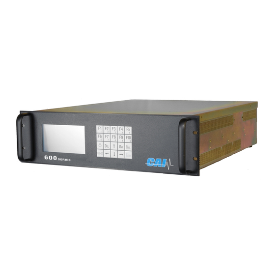
- Page 1 6 5 0 CLD/O 6 5 0 6 5 0 CLD/O CLD/O S E R I E S USER’S MANUAL Note: For Analyzers Sold After June, 2007 Please See Addendum Starting After Page 86 of This Manual 1312 West Grove Avenue Orange, CA 92865-4134 Phone: 714-974-5560 Fax: 714-921-2531 www.gasanalyzers.com...
- Page 2 Section 1 Model 650 Noxygen Analyzer 650 Quick Start Guide Plug in the analyzer and turn the power on. Connect the appropriate gas lines and vents to the analyzer. Allow the analyzer to stabilize for at least one (1) hour. During the analyzer’s stabilization period, setup the analyzer to the desired configuration.
-
Page 3: Table Of Contents
Section 1 Model 650 Noxygen Analyzer TABLE OF CONTENTS Introduction........................10 1.1. Overview........................10 1.2. Unpacking Instructions .....................10 1.3. Reporting Damage ....................10 1.4. Contact Information ....................10 1.5. Warranty Certificate....................11 Features..........................12 2.1. Description .......................12 2.2. Features-General .....................12 2.3. Model 650 CLD/Paramagnetic Specifications ............13 Installation........................14 3.1. - Page 4 Section 1 Model 650 Noxygen Analyzer 5.1. The Main Menu......................24 Menu Structure ......................25 6.1. User Functions (Level 1) ..................25 6.2. Advanced User Functions (Level 2) .................25 6.3. Maintenance Functions (Level 3) ................25 6.4. System User Functions (Level 4) ................25 Main Menu Function Descriptions ................26 7.1.
- Page 5 Section 1 Model 650 Noxygen Analyzer 7.8.10. F2 Change Auto Range Limits ................. 40 7.8.11. Alarms ........................41 7.8.12. Password........................41 7.8.13. F1 Enter Password....................42 7.8.14. F2 Change Password....................42 7.8.15. F3 Reset Passwords ....................42 7.8.16. Linearization ......................43 7.8.17.
- Page 6 Section 1 Model 650 Noxygen Analyzer 8.7. Main Electronic Board Connectors ................56 8.8. Reaction Chamber....................57 8.9. Relay Board Connections..................58 Operation........................59 9.1. Preparation for Operation ..................59 9.2. Operation........................59 9.3. Shut Down Procedure ....................60 10. Functional Description....................61 10.1. Operating Principle- NO/NO ..................61 10.1.1.
- Page 7 Section 1 Model 650 Noxygen Analyzer Table of Figures Figure 3-1 AC Power Switch, Connector, and Fuse ..................15 Figure 3-2 EMI Suppressor..........................15 Figure 4-1 Measurement Screen ........................18 Figure 4-2 Keyboard ............................22 Figure 5-1 Main Menu on Power Up Screen ....................24 Figure 5-2 Main User Menu (Level 4) ......................
- Page 8 Section 1 Model 650 Noxygen Analyzer Figure 7-31 Check Calibration ........................35 Figure 7-32 F5 Reset calibration values ......................35 Figure 7-33 Reset calibration values ......................35 Figure 7-34 Range Select ..........................35 Figure 7-35 Range ............................35 Figure 7-36 Main menu (User level 4) ......................36 Figure 7-37 Setup menu 1 ..........................
- Page 9 Section 1 Model 650 Noxygen Analyzer Figure 7-68 Output Assignments ........................46 Figure 7-69 Output Ranges ..........................46 Figure 7-70 Status Line........................... 47 Figure 7-71 Menu Settings Screen ......................... 47 Figure 7-72 Set NO Purge and Measure Time....................47 Figure 7-73 Set Converter Efficiency ......................48 Figure 7-74 Set Time Constant........................
-
Page 10: Introduction
Section 1 Model 650 Noxygen Analyzer Introduction 1.1. Overview Congratulations and thank you! You have just purchased one of the most reliable gas analyzers in the world. Before using the analyzer, please familiarize yourself with its operation by reading this manual. If you have any questions, please do not hesitate to call California Analytical Instruments for assistance. -
Page 11: Warranty Certificate
(but not in exce ss of one year) stated on the label at the time of delivery or 90 days; CAI may from time to time provide a special pr inted warranty with respect to a certain product, and where applicable, such warranty shall be deemed incorporated herein by reference;... -
Page 12: Features
Features 2.1. Description The CAI Model 650 NO Analyzer is a highly sensitive chemiluminescent (CLD) gas analyzer and a reliable paramagnetic oxygen analyzer. It measures oxides of nitrogen gas and dry basis oxygen concentrations in industrial and vehicle emission applications. -
Page 13: Model 650 Cld/Paramagnetic Specifications
Section 2 Model 650 Noxygen Analyzer 2.3. Model 650 CLD/Paramagnetic Specifications Chemiluminescence (CLD) Photodiode /Paramagnetic (O DETECTORS 0-1 to 3,000 ppm NO or NO (Four user-definable ranges) NO/NOx RANGES (Higher Ranges Available upon Request) 0-25% OXYGEN RANGE T90 < 3 Seconds to 60 Seconds Adjustable RESPONSE TIME 0.03 ppM NO/NO (Displays 5 significant digits) -
Page 14: Installation
Section 3 Model 650 Noxygen Analyzer Installation 3.1. General The instrument is designed for industrial applications. These installation instructions are for a typical site. Any questions regarding specific installation situations should be directed Technical Service of California Analytical Instruments, Inc. 3.2. -
Page 15: Electrical
Section 3 Model 650 Noxygen Analyzer 3.3. Electrical All wiring is connected at the rear of the instrument. The AC power is connected to the power/fuse/switch as shown below: Figure 3-1 AC Power Switch, Connector, and Fuse NOTE: A defective ground may affect the operation of the instrument. The output voltages are connected per Table 8.1.1. -
Page 16: Analog Output Connections
Section 3 Model 650 Noxygen Analyzer 3.4. Analog Output Connections (Appendix) See Appendix for connector pinouts located on the analyzer rear panel. Remote range identification and range selection are obtained via the rear panel connections. When a range is selected, the corresponding control line is pulled low to zero VDC. Ranges not selected will remain at approximately 5 VDC. -
Page 17: Sampling Requirements
Section 3 Model 650 Noxygen Analyzer 3.8. Sampling Requirements 3.8.1. Filtration Dust must be eliminated completely. Use filters as necessary. The final filter must be capable of removing particles larger than 4 microns. 3.8.2. Condensation Dew point of the sample gases must be lower than the instrument temperature to prevent accidental condensation within the instrument. -
Page 18: Basic Operation
Section 4 Model 650 Noxygen Analyzer Basic Operation The operation of the digital microprocessor conforms to the guidelines of the AK committee, originally developed in the German automotive industry. Via the serial port of the MSR-Card, the analyzer can be remote-controlled by a master computer. The serial communication fully corresponds to the specifications of the AK protocol. -
Page 19: Menu Tree
Section 4 Model 650 Noxygen Analyzer 4.2. Menu Tree Main Menu (All access) F1 Measurement F2 Purge Analyzer F3 Diagnostics F4 Calibration F5 Setup F6 Remote/Manual F7 Stand by Measurement F1 Toggles between NO and NO F1 NO/NO F2 Toggles on NO and NO F2 Dual Mode F3 Displays Diagnostics Screen F3 Diagnostics... - Page 20 Section 4 Model 650 Noxygen Analyzer Main Menu Calibration (All access) F1 Auto calibration F2 Manual calibration F1 Measurement F3 Display deviations F2 Purge Analyzer F4 Check calibration F3 Diagnostics F5 Reset calibration values F4 Calibration F6 Range select F5 Setup F6 Remote/Manual F7 Stand by Auto calibration...
- Page 21 Section 4 Model 650 Noxygen Analyzer Setup Main Menu (All access) (All access) F1 Span gas concentrations F1 Measurement F2 Calibrations settings F2 Purge Analyzer F3 Range limits F3 Diagnostics F4 Alarms F4 Calibration F5 Password F5 Setup F6 Linearization F6 Remote/Manual F7 System settings F7 Stand by...
-
Page 22: Keyboard
Section 4 Model 650 Noxygen Analyzer 4.3. Keyboard Combined control / numeral keys To the main menu Display lighting Cancel, back to on / off Main Back the last menu Delete key End input, open selected field for input Switch-over of the keyboard Arrow keys for selecting the functions and numeral / control keys editing fields and for scrolling possible input values... -
Page 23: Operating Structure
A password can be assigned to each operating level. Only the system user, who normally has the highest operating priority, can assign the password. At the factory, the default passwords for the CAI analyzers are set as follows: User: Advanced user:... -
Page 24: The Main Menu
Section 5 Model 650 Noxygen Analyzer 5.1. The Main Menu Upon power up, the CAI logo is first displayed and then the main menu appears as below: NOTE: Access Level Indication Figure 5-1 Main Menu on Power Up Screen NOTE: F6 is not available because, on initial start up, the analyzer reverts to ONLY Level 1 access. -
Page 25: Menu Structure
Section 6 Model 650 Noxygen Analyzer Menu Structure There are 4 operating levels based on the level of your password. This section shows the access rights of the single levels. 6.1. User Functions (Level 1) Main Menu Setup Menu Password Menu Measurements Password Enter password... -
Page 26: Main Menu Function Descriptions
Section 7 Model 650 Noxygen Analyzer Main Menu Function Descriptions 7.1. F1 Measurements The measurements screen is activated by pressing F1 on the Main Menu screen. Figure 7-1 Main Menu Screen 7.1.1. F1 NO or NO Measurement The NO/NO content is displayed in ppm. Pressing F1 switches between measuring the sample gas for NO or NO only. -
Page 27: F2 No + No
Section 7 Model 650 Noxygen Analyzer 7.1.2. F2 NO + NO Measurement The F2 function activates the “hold and sample“feature which allows the analyzer automatically switch between NO and NO measurement. The time duration for the sample read is set up in the Setup Menu. The analyzer will read and display the NO (converter is bypassed) value. -
Page 28: Select Range
Section 7 Model 650 Noxygen Analyzer 7.3. Select Range With the arrow keys, the ranges 1 to 4 can be selected and locked in which will disable the auto range capability. Continue pressing the arrow keys will recycle the analyzer back to auto range. -
Page 29: F3 Diagnostics
Section 7 Model 650 Noxygen Analyzer 7.5. F3 Diagnostics F3 from the Main Menu activates the Diagnostics function. As described in Section 7.1.3, F3 brings up the two diagnostics screens. The Diagnostics screens may be brought up from EITHER the Main Menu or the Measurements screen. NOTE: Access level is 4. -
Page 30: F1 Automatic Calibration
Section 7 Model 650 Noxygen Analyzer 7.6.1. F1 Automatic Calibration From the Calibrations screen, F1 starts automatic calibration. If auto range is selected, the actual range in use will be calibrated. Auto calibration works as follows: First zero gas is purged a certain time, called purge-time. -
Page 31: F2 Manual Calibration
Section 7 Model 650 Noxygen Analyzer 7.6.2. F2 Manual Calibration Figure 7-14 F2 Manual Calibration From the Calibration screen, F2 starts manual calibration. If auto range is selected, calibration is not possible, and the appropriate range can be selected. In the manual calibrations menu, five options are possible: F1 Flow zero gas F2 Flow span gas... -
Page 32: Figure 7-18 Range Select
Section 7 Model 650 Noxygen Analyzer From the manual calibration menu, the range to calibrate can be chosen by pressing F3. Figure 7-18 Range select Figure 7-19 Selected range 1 Figure 7-20 Selected range 2 Figure 7-21 Selected range 3 Figure 7-22 Selected range 4 Figure 7-23 Selected auto range California Analytical Model 650 Noxygen... -
Page 33: F3 Display Deviations
Section 7 Model 650 Noxygen Analyzer 7.7. F3 Display Deviations Figure 7-24 F3 Display deviations After every calibration, the deviations are calculated for zero and for span gas. F1 shows zero gas deviations F2 shows span gas deviations F3 Deviations of zero gas during verifying F4 Deviations of span gas during verifying... -
Page 34: Absolute Zero Gas Deviation
Section 7 Model 650 Noxygen Analyzer 7.7.1. Absolute Zero Gas Deviation Absolute zero gas deviation is zero gas content calculated by the factory polynom related to the range limit of the calibrated range. Figure 7-26 Zero gas deviations Figure 7-27 Zero gas deviations verifying 7.7.2. -
Page 35: F4 Check Calibration
Section 7 Model 650 Noxygen Analyzer 7.7.5. F4 Check Calibration Figure 7-30 F4 Check calibration Figure 7-31 Check Calibration There is a default calibration. Pressing F4, activates an automatic zero and span check for verification. 7.7.6. F5 Reset Calibration Values Figure 7-32 F5 Reset calibration values Figure 7-33 Reset calibration values There is a default calibration. -
Page 36: F5 Setup
Section 7 Model 650 Noxygen Analyzer 7.8. F5 Setup From the Main Menu, F5 brings up the setup menu. Span gas concentrations, calibration settings, range limits, alarms, password, linear ization, system and measure settings can be changed. The Setup menu begins as shown below. A description of each parameter is shown in the information box. -
Page 37: F1 Span Gas Concentration
Section 7 Model 650 Noxygen Analyzer 7.8.1. F1 Span Gas Concentration For calibration, it is necessary to input the concentration of the span gas in ppm. For every range, the span gas concentration can be changed. After pressing F1 in the setup menu, a screen appears in which changes can be made. -
Page 38: F1 Times
Section 7 Model 650 Noxygen Analyzer 7.8.3. F1 Times There are four times (in seconds) for auto calibration that can be changed. Purge, measuring, calibration and verifying time. Changes are made and saved as above. Figure 7-41 Setup-times 7.8.4. F2 Measuring Deviations During auto calibration, the measured value is only saved if it is within a certain time within an upper and a lower limit. -
Page 39: F4 Calibrations Via Solenoids
Section 7 Model 650 Noxygen Analyzer 7.8.6. F4 Calibrations via Solenoids Calibrations can be made by using the solenoids for zero and span gas or by using the pump. Calibration via valves means that the zero gas is flown by the zero gas solenoid and the span gas is flown by the span gas solenoid. -
Page 40: F1 Range 1-4 (Change Upper Range Limits)
Section 7 Model 650 Noxygen Analyzer 7.8.9. F1 Range 1-4 (Change Upper Range Limits) In this menu the upper range limits can be changed. The new settings are saved by pressing MAIN or BACK. The auto range limit s are automatically adapted. This means that if the upper range limit of range 1 for example has reached 90% of the upper range limit in the auto range mode, it is switched automatically to the second range. -
Page 41: Alarms
Section 7 Model 650 Noxygen Analyzer 7.8.11. Alarms Error reports are always displayed in the lowest line of the screen. There are two pressures, three temperatures, one concentration and two voltages with alarm limits that can be defined. The user can define the range limits and, if exceeded, will display an error-message. -
Page 42: F1 Enter Password
Section 7 Model 650 Noxygen Analyzer 7.8.13. F1 Enter Password To change access level, press F1. The following screen appears: Figure 7-52 Access Level Screen F1 to F4 selects an access level. Move the cursor to the access level to be modified. You must enter the correct password for the access level desired. -
Page 43: Linearization
Section 7 Model 650 Noxygen Analyzer 7.8.16. Linearization Pressing F6 on the Setup screen brings up the Linearization screen. The analyzer can be linearized by a polynom with 5 coefficients. By pressing F1, these 5 coefficients can changed for each range. By pressing F2, the raw value can be displayed. -
Page 44: F1 Real Time Clock
Section 7 Model 650 Noxygen Analyzer 7.8.18. F1 Real Time Clock This brings up the clock time set screen; auto cal and auto cal enable screens. Figure 7-60 Clock and Timing Setup Screen Figure 7-61 Set Clock Screen F1 brings up the clock set screen The current time may be set by using the cursor to highlight the entry and using the numeric keys to change the values. -
Page 45: F3 Set Auto Cal Ranges
Section 7 Model 650 Noxygen Analyzer 7.8.20. F3 Set Auto Cal Ranges Figure 7-64 Clock and Timing Setup Screen 7.8.21. F4 Autocalibration on/off Figure 7-65 F4 Toggles Auto Cal ON of OFF 7.8.22. Auto calibration Displays system time and status of autocalibration. Figure 7-66 Autocalibration Status California Analytical Model 650 Noxygen Operators Manual... -
Page 46: F2 Displays Tcp/Ip Address
Section 7 Model 650 Noxygen Analyzer 7.8.23. F2 Displays TCP/IP Address Figure 7-67 TCP/IP Address 7.8.24. F3 Displays Output Signal Assignments (Used to Adjust Analog Output Channels) Figure 7-68 Output Assignments 7.8.25. F4 Displays Output Ranges (Used to Adjust Scale of Analog Output Channels) Figure 7-69 Output Ranges California Analytical Model 650 Noxygen Operators Manual... -
Page 47: F5 Turns Status Line On Or Off
Section 7 Model 650 Noxygen Analyzer 7.8.26. F5 Turns Status Line On or Off The status line displays the AK Protocol action on the top line of the display. Status Line Figure 7-70 Status Line 7.8.27. F8 Measure Settings This screen allows several of the system settings to be displayed and modified. Figure 7-71 Menu Settings Screen 7.8.28. -
Page 48: F2 Converter Efficiency
Section 7 Model 650 Noxygen Analyzer 7.8.29. F2 Converter Efficiency F2 on the Menu Settings screen allows the NO to NO converter efficiency to be set to the actual measured converter efficiency. A value of 100% equals 1.00. F2 will prompt the operator through the NO efficiency test using a NO generator. -
Page 49: F10 Displays The Current Analyzer And Software Versions
Section 7 Model 650 Noxygen Analyzer 7.8.32. F10 Displays the Current Analyzer and Software Versions This displays the analyzer’s information, including the factory recommended air and sample pressure settings. Figure 7-76 Analyzer Information Version Figure 7-77 Software Version California Analytical Model 650 Noxygen Operators Manual 650 NOXO2_v9.0.doc Page 49 of 86... -
Page 50: F7 Remote / Manual Control
Figure 7-78 Remote manual control Main Menu (User Level 4) 7.10. F8 Standby In Standby mode, pump is turned off and the solenoids are closed. The CAI logo is displayed. Figure 7-79 Standby selection Figure 7-80 Standby screen Main Menu (User Level 4) -
Page 51: Analyzer Components
Section 8 Model 650 Noxygen Analyzer Analyzer Components 8.1. Rear Panel The following details the rear panel connections: Figure 32: Rear Panel Sample Gas Inlet: Feeds sample gas to the analyzer. ¼ Inch Tube. Sample Gas Bypass Outlet: Exhaust for sample. ¼ Inch Tube. Air Inlet: For feeding hydrocarbon free air or oxygen to the ozone generator. -
Page 52: Main Connector (Standard 28 Pin Connector)
Section 8 Model 650 Noxygen Analyzer 8.2. Main Connector (Standard 28 Pin Connector) 8.2.1. Main Connector (Standard 28 Pin Connector) Signal Function Signal Function Analog Output Ground (Analog) Digital Input Control Range 3 Analog Output Real Time Digital Input Control Range 4 Analog Output Digital Input Auto Cal... -
Page 53: Digital Outputs - Tcp/Ip (8 Pin Rj-47 Connector)
Section 8 Model 650 Noxygen Analyzer 8.2.4. Digital Outputs – TCP/IP (8 Pin RJ-47 Connector) Function TDX+ TDX- RXD+ Open Open RXD- LNLED LNLED IMPORTANT TIP: For direct connect to a PC a crossover cable is required. Connection to a hub requires a straight cable. California Analytical Model 650 Noxygen Operators Manual 650 NOXO2_v9.0.doc... -
Page 54: Internal Component Locations
Section 8 Model 650 Noxygen Analyzer 8.3. Internal Component Locations Figure 8-1 Major Internal Components Electronics: Includes instrument electronics. (See Main Electronic Board) Solenoid Valve: Switches flow between the NO and NO mode. NO/NO Optional Internal Sample Pump: Provides sample to analyzer. (Not shown) Ozonator: Contains UV Lamp. -
Page 55: Main Electronics Board (Potentiometers)
Section 8 Model 650 Noxygen Analyzer 8.4. Main Electronics Board (Potentiometers) RP1 to RP17 RP18 8.5. Main Electronic Board Potentiometers RP1 : EPC 9.5V Sample Set RP10 : Chiller Zero Temp Set RP2 : EPC 9.5V Air Set RP11 : Chiller Span Temp Set RP3 : O3 Cutoff RP12 : Chiller Temp Set RP4 : Cell Temp Set... -
Page 56: Main Electronics Board (Connectors)
Section 8 Model 650 Noxygen Analyzer 8.6. Main Electronics Board (Connectors) Test Points Voltage Output Clearly Resistor Stand 8.7. Main Electronic Board Connectors : Test Points : Test Points : Test Points : EPC Air Valve : Test Points : Digital Output 2 (DIDO Board) : EPC Sample : Sample Transducer J10 : Spare Digital Output... -
Page 57: Reaction Chamber
Section 8 Model 650 Noxygen Analyzer 8.8. Reaction Chamber Pressure Exhaust Sample Ozone Reaction Chamber Assembly (Oven Side) Power Input Inverting Amplifier Adjust Main Gain Zero Adjust Board Adjust Figure 8-2 Reaction Chamber Pre-Amplifier California Analytical Model 650 Noxygen Operators Manual 650 NOXO2_v9.0.doc Page 57 of 86... -
Page 58: Relay Board Connections
Section 8 Model 650 Noxygen Analyzer 8.9. Relay Board Connections J32 – Connects to Figure 8-3 Relay Board Connections AC Input Power Supply 1 Power Supply 2 Power Supply 3 Ozone Lamp Pump Power Cell Heater Oven Heater Converter Heater Pump Heater Optional O2 Heater Optional NH3 Heater... -
Page 59: Operation
Section 9 Model 650 Noxygen Analyzer Operation 9.1. Preparation for Operation Check that the external plumbing and wiring have been connected correctly, as described in this manual. NOTE: The internal ozone generator requires approximately 1 hour of continuous operation for the analyzer to achieve full zero and span calibration stability. 9.2. -
Page 60: Shut Down Procedure
Section 9 Model 650 Noxygen Analyzer Instrument Power: Turn instrument power on and allow the reaction chamber and NO converter to stabilize before turning on the sample pump and/or connecting the sample line. Sampling System: Prepare and check the sample system. Check the sample pressure as indicated in the factory settings screen. -
Page 61: Functional Description
Section 10 Model 650 Noxygen Analyzer Functional Description 10.1. Operating Principle- NO/NO The California Analytical Model 650 Analyzer utilizes the chemiluminescent method determination of oxides of nitrogen (NO or NO ) in a sample gas. In the NO mode, the NO in the sample is quantitatively converted to NO by gas phase oxidation with molecular ozone produced by the UV reaction of cylinder air. -
Page 62: 10.2. Principle Of Operation-Oxygen
Section 10 Model 650 Noxygen Analyzer 10.2. Principle of Operation-Oxygen The paramagnetic susceptibility of oxygen is significantly greater than that of other common gases, and consequently, the molecules of oxygen are attracted much more strongly by a magnetic field than the molecules of the other gases. Most of the other gases are slightly diamagnetic, which means that their molecules are then repelled by a magnetic field. -
Page 63: Figure 10-3 Principle Of Operation
Section 10 Model 650 Noxygen Analyzer amplifier, which in turn is fed to the feedback coil of the measuring cell. If the oxygen content of the gas sample changes, the corresponding current output of the amplifier, which is proportional to the oxygen content, produces a magnetic field in the feedback coil opposing the forces and thereby causing the dumbbell to rotate. -
Page 64: Cross Sensitivity Of Gases
Section 10 Model 650 Noxygen Analyzer 10.3. Cross sensitivity of gases The very high magnetic susceptibility of oxygen is the basis of the paramagnetic measuring principle. In comparison to oxygen, other gases have such a minor susceptibility that most of them are insignificant. -
Page 65: Table 10-1 Cross Sensitivity Of Gases
Section 10 Model 650 Noxygen Analyzer Table 10-1 Cross Sensitivity of gases All values based on nitrogen 0% / oxygen 100% Formula Argon -0.23 -0.25 Acetylene -0.26 -0.28 Acetone -0.63 -0.69 Acetaidehyde -0.31 -0.34 Ammonia -0.17 -0.19 Benzene -1.24 -1.34 Bromine -1.78 -1.97... -
Page 66: Reaction Chamber Servicing
Section 11 Model 650 Noxygen Analyzer Reaction Chamber Servicing 11.1. Disassembly Procedure Shut off ALL gas flow. Remove power from the instrument. Remove the top cover retaining screws. Remove all 4 tubes from the 4 way cross. Remove the 4 screws securing the photodiode and reaction chamber from the oven. -
Page 67: Troubleshooting
NO to NO conversion efficiency utilizing a NO generator. The CAI Model NOxGen may be used for this procedure. A short test using NO calibration gas is also defined in the U.S Federal Register, Title 40, Part 86.332.79 (e). -
Page 68: Ak Protocol Format
Section 13 Model 650 Noxygen Analyzer AK Protocol Format The master computer and the Model 650 analyzer communicates via the RS232 serial link. The Model 650 analyzer acts as a “slave" and only responds to commands. Serial Interface Parameters: Baud from 300 to 9600 bps, can be selected via the display. 7 or 8 data bits, 1 or 2 stop bits, and the parity (yes/no). -
Page 69: 13.3. General Ak Requirements
Section 13 Model 650 Noxygen Analyzer 13.3. General AK Requirements If the command message contains no error, the acknowledge message contains the echo of the function code and the error status number (1 to 9). If the transfer was faulty or the function code unknown, the answer contains four question marks (example. - Page 70 Section 13 Model 650 Noxygen Analyzer Set measuring range AEMB: Command Response Description _AEMB_K0 _AEMB_s_Mn Current measuring range is responded Measuring range limit AMBE: Command Response Description _AMBE_K0 _AMBE_s_M1_w.w_M2_x.x_M3_y.y_ All existing measuring range limits are M4_z.z responded _AMBE_K0_Mn _AMBE_s_Mn_z.z Range limit of Range Mn is responded Calibration gas concentrations AKAK: Command...
- Page 71 Section 13 Model 650 Noxygen Analyzer Possible states: SREM: STBY: SENO: SARE: SDRY: remote standby NO mode Autorange on Chiller on SMAN: SPAU: SMAN: SARA: SWET: manual pause mode Autorange off Chiller off SMGA: measuring gas SNGA: zero gas SEGA: end gas SATK SNGA: zero gas during...
- Page 72 Section 13 Model 650 Noxygen Analyzer Error status ASTF: Command Response Description _ASTF_K0 _ASTF_s_f1_f2_f3_.._f15 Current error number is responded Errors: Sample Pressure Failure EPC Coil Sample Failure Air Pressure Failure EPC Coil Air Failure Oven Temp Failure Range Overflow Converter Temp Failure ADC Range Overflow Pump Temp Failure ADC Range Underflow...
- Page 73 Section 13 Model 650 Noxygen Analyzer Description of x: Oven Temp Converter Temp Pump Temp Diode Temp Cell Temp Peltier Temp Reaction Chamber Temp ADRU: Pressures Command Response Description _ADRU_K0 _ADRU_s_z.z_y.y_... All pressures are responded _ADRU_K0_x _ADRU_s_z.z Pressure of x is responded Description of x: Sample Pressure Air Pressure...
- Page 74 Section 13 Model 650 Noxygen Analyzer AAEG: Deviation from end point after autocalibration Command Response Description _AAEG_K0 _AANG_s_M1_z.z_da_dr_ Deviation from end point after M2_z.z_da_dr_ M3_z.z_da_dr_ autocalibration M4_z.z_da_dr_ AFDA: Purge and Autocalibration times Command Response Description _AFDA_K0_SATK _AFDA_s_z_y_x_w_Z.Z Autocalibration times: z: Purge time y: Calibration time x: Total Calibration time w: Verify time...
- Page 75 Section 13 Model 650 Noxygen Analyzer ASYZ: Respond System Time Command Response Description _ASYZ_K0_ _ASYZ_s_yymmdd_hhmmss Respond system time yymmdd:year, month, day (each 2 characters wide, no spaces) hhmmss:hour, minutes, seconds) AT90: Respond Lowpass filter time Command Response Description _AT90_K0_ _AT90_s_t Respond lowpass filter time t=filter time in seconds ADAL: Diagnostic alarm limits...
-
Page 76: Control Commands
Section 13 Model 650 Noxygen Analyzer 13.5. Control commands Reset SRES: Command Response Description _SRES_K0 _SRES_s Reset Pause SPAU: Command Response Description _SPAU_K0 _SPAU_s Pause mode Standby STBY: Command Response Description _STBY_K0 _STBY_s Standby mode Open valve for zero gas calibration SNGA: Command Response... - Page 77 Section 13 Model 650 Noxygen Analyzer SKOP: Converter Check Command Response Description _SKOP_K0 _SKOP_s Change status to SKOP and activate sample pump (only for compatibility) SWET: Chiller off – Wet mode measuring Command Response Description _SWET_K0 _SWET_s Switch chiller off SDRY: Chiller on –...
- Page 78 Section 13 Model 650 Noxygen Analyzer Start measuring SMGA: Command Response Description _SMGA_K0 _SMGA_s Start measuring Turn on pump for sample gas SNKA: Saves measured value as new offset. Command Response Description _SNKA_K0 _SNKA_s Saves measured value of actual range as new offset if zero valve is opened SEKA: Saves measured value as new span value Command...
-
Page 79: Settings
NOTE: To change device identification, you must first rename the device to “RESET”. Now a name up to 40 letters can be given. NOTE: The device name must not have any blanks between, i.e. “CAI CLD” is not allowed. You can use underlines, i.e. “CAI_CLD”. - Page 80 Section 13 Model 650 Noxygen Analyzer EPAR: Set autocalibration tolerance values Command Response Description _EPAR_K0_SATK_z.z_y.y_x.x_w.w _EPAR_s Autocalibration Tolerance value (%): z.z= Range 1 y.y= Range 2 x.x= Range 3 w.w= Range 4 ESYZ: Set System Time Command Response Description _ESYZ_K0_yymmdd_hhmmss _ESYA_s Respond system time: yymmdd:year, month, day (each...
-
Page 81: Abbreviations Used
Section 13 Model 650 Noxygen Analyzer 13.7. Abbreviations used : Measuring range number M1 .. M4 : Measuring Range 1 .. 4 w.w .. : Numerical value Z.Z. : Number : Numeric integer value a0 .. a4 : Polynom coefficients : Status yyymmdd :Date of format year, month and day with 2 characters each and no spaces... -
Page 82: Appendix
Section 14 Model 650 Noxygen Analyzer Appendix 14.1. MODEL 650 NO Flow Diagrams EPCV2 OZONE AIR/0 EXHAUST DETECTOR LAMP SAMPLE EPCV1 CONVERTER BYPASS 650 - NOXYGEN FLOW DIAGRAM Figure 14-1: Standard Analyzer California Analytical Model 650 Noxygen Operators Manual 650 NOXO2_v9.0.doc Page 82 of 86... -
Page 83: Figure 14-2: Standard Analyzer With Optional Zero/Span Solenoids
Section 14 Model 650 Noxygen Analyzer EPCV2 OZONE AIR/0 EXHAUST DETECTOR LAMP SAMPLE EPCV1 Zero CONVERTER Span BYPASS 650 - NOXYGEN FLOW DIAGRAM - W/ZERO/SPAN S/V Figure 14-2: Standard Analyzer with Optional Zero/Span Solenoids California Analytical Model 650 Noxygen Operators Manual 650 NOXO2_v9.0.doc Page 83 of 86... -
Page 84: Figure 14-3: Standard Analyzer With Optional Sample Pump
Section 14 Model 650 Noxygen Analyzer EPCV2 OZONE AIR/0 EXHAUST DETECTOR LAMP SAMPLE EPCV1 CONVERTER BYPASS 650 - NOXYGEN FLOW DIAGRAM - W/PUMP Figure 14-3: Standard Analyzer with Optional Sample Pump California Analytical Model 650 Noxygen Operators Manual 650 NOXO2_v9.0.doc Page 84 of 86... -
Page 85: Figure 14-4: Standard Analyzer With Optional Sample Pump And Zero/Span Solenoids
Section 14 Model 650 Noxygen Analyzer EPCV2 OZONE AIR/0 EXHAUST DETECTOR LAMP SAMPLE EPCV1 ZERO CONVERTER SPAN BYPASS 650 - NOXYGEN FLOW DIAGRAM W/PUMP AND ZERO/SPAN S/V Figure 14-4: Standard Analyzer with Optional Sample Pump and Zero/Span Solenoids California Analytical Model 650 Noxygen Operators Manual 650 NOXO2_v9.0.doc Page 85 of 86... -
Page 86: 14.2. Electrical Block Diagram
Section 14 Model 650 Noxygen Analyzer 14.2. Electrical Block Diagram California Analytical Model 650 Noxygen Operators Manual 650 NOXO2_v9.0.doc Page 86 of 86... - Page 87 ADDENDUM TABLE OF CONTENTS ADDENDUM STARTING AFTER JUNE, 2007 Section Title Page 1.0. Introduction ------------------------------------------------------------------------------------- 2.0. Operation of Measurement Keys ----------------------------------------------------------------- 2.1. Over Range -------------------------------------------------------------------------------- 2.2. Diagnostics---------------------------------------------------------------------------------- 2.3. Zero ------------------------------------------------------------------------------------------ 2.4. Span ----------------------------------------------------------------------------------------- 2.5. Range Limits------------------------------------------------------------------------------- 2.6. Span Values ------------------------------------------------------------------------------- 2.7.
- Page 88 ADDENDUM 13.5 Starting With SERIAL NUMBER UO6081 1.0 INTRODUCTION The Model 600 CLD Series Instruments starting with Serial Number U06081 have several new Hardware and Software features. The Hardware includes the use of a new memory system, isolation of the analog output signals and 15 relays that are used to buffer the many new digital output signals that are now available.
- Page 89 ADDENDUM 2.0 OPERATION OF MEASUREMENT KEYS Note: The & Keys continue to be used to view a complete list of menu items. 2.1 Over Range 888888 In the MEASUREMENT mode only, any value that exceeds the “range” by more than10% will be displayed as 888888. 2.2 Diagnostics: Use F3 to toggle between MEASUREMENT and DIAGNOSTIC.
- Page 90 ADDENDUM 2.4 Span: From the MEASUREMENT Screen select the required range then press F6. Note: For instruments with an Internal Span Solenoid select Calibration by Valves. (Main, F5, F2, F4) 2 versions Span Gas will be enabled and the observed results can be used to evaluate instrument performance.
- Page 91 ADDENDUM 2.5 Range Limits: F8 From the MEASUREMENT Screen; 2 versions The standard analyzer is factory configured with 4 Physical Ranges of 3, 30, 300, 3,000 PPM. The optional high level analyzer is factory configured with 4 Physical Ranges of 5, 50, 500, 500 The operator can change the number of ranges and select a more convenient full scale concentration if required.
- Page 92 ADDENDUM 2.7 Outputs: F10 From the MEASUREMENT Screen Use the ↕ to select the desired Output. Press Enter to select Use the ↕ to select the desired Signal. Press Enter to select Use this screen to define the signals and their location that will be monitored by a remote reordering device.
- Page 93 ADDENDUM 3.0 NEW FUNCTIONS 3.1 Auto Start Up: (Main, F5, F7, F7) All key analyzer parameters are stored in a secure memory location and retained when power is removed In the event of an unexpected power failure it may be desirable to change some parameters until an operator can resume control.
- Page 94 ADDENDUM 3.2 Alarms On/Off: (Main, F5, F7) All key analyzer parameters are stored in a secure memory location and retained when power is removed. In the event of an unexpected power failure it may be desirable to change some parameters until an operator can resume control. This screen may be used to establish several desirable special instrument start-up parameters that define how the analyzer recovers from loss of AC power.
- Page 95 ADDENDUM 3.3 Offset & Gain: (Main, F4, F3, F5) This screen can be used to provide an additional means to display calibration deviations. The OFFSET is the value stored during zero calibration. The GAIN is the value stored during span gas calibration using the operator defined calibration gas.
- Page 96 ADDENDUM The D-A CALIBRATION screen will then be used to complete the calibration procedure. This screen provides a section that is used to record the zero signal corrections (zero offset) and a second area to record the 100% signal corrections (Gain) for each of the four output signals that may be defined to develop a voltage or current signal.
- Page 97 ADDENDUM Procedure 3.4.1 From the Main Menu press F5,F7,F3, to obtain following screen: 3.4.2. Use the ↕ to highlight the outputs that require calibration. 3.4.3. Press enter so you provide access to all the menu of signals that are available. (Real Time, N0, N0x, Calibration, Sample Pressure, etc.) 3.4.4.
- Page 98 ADDENDUM 3.4.5. Press BACK to return to the SYSTEM SETUP screen (Main,F5, F7) 3.4.6. Press F8 to obtain the following screen Main, F5, F7, F8 3.4.7. Use the ↕ to select the desired output press ENTER. 3.4.8. Press F1 to select a ZERO signal and observe the results on the remote device 3.4.9.
- Page 99 Archive Time is the Time in seconds between each set of data points. If “zero” no data is stored in the SEC data files. The SEC data files are in .CSV format for direct import into Excel. CAI can provide the tools necessary to download these files.
- Page 100 ADDENDUM TABLE A 600 SERIES CLD DATA ARCHIVE FILES Time, Date, Month, Year, Error Index, TimeStamp, NO Conc, NO2 Conc, NOx Conc, NH3 Conc, Concentration, Detector Volts, Range, Auto / Manual, Span Gas, Offset, Gain, Sample Pressure, Sample Flow, Sample EPV Volts, Air Pressure, Ozone Flow, Ozone EPC Volts,...
- Page 101 ADDENDUM 3.6 User Digital Outputs Overview The 600 CLD Series of instruments have 15 solid state, optically coupled, isolated relays that can be programmed by the operator to indicate the status of numerous digital conditions The available digital signals consist of a SERVICE group, that can be used to externally monitor a number of conditions to aid in preventative maintenance and diagnostics.
- Page 102 ADDENDUM The operator can select from the following the desired SERVICE or STATUS groups that are to be digitally monitored. TABLE B User DO Screen Index Service Group Display Sample Pressure Failure SampleP Air Pressure Failure AirP Oven Temp Failure OvenT (hcld only) Converter Temp Failure...
- Page 103 ADDENDUM TABLE C User DO Screen Index Status Group Display In Remote InRem AutoRange AutoR Range 1 Range 2 Range 3 Range 4 In Calibrate InCal In Zero Zero In Span Span In Sample Sample In NO Mode InNO In NOx Mode (605 only) InNOx In Wet Mode (HCLD only) InWet...
- Page 104 ADDENDUM OPERATION Use (Main, F5, F9) to select the first seven outputs. Use the ↕ to select the desired output. Press ENTER and use ↕ to select desired item. Press ENTER to save selection Note: The 600 CLD has 15 user selectable isolated digital outputs from the list of 40 in TABLE B &...
- Page 105 ADDENDUM 3.7 Cal Analog Output: (Main, F5, F8,) Use F8 to toggle on/off Normally, during Auto Cal the Sample and Hold Outputs NO, NOx and NO2 are held at the last process value. If Cal Analog Output is set “On” then the values are not held, and the Real Time value is Output.
- Page 106 ADDENDUM 4.0 CHANGES TO EXISTING FUNCTIONS 4.1 Saved or Outside Limits During Manual Calibration the following screens will be displayed to indicate the instruments response to the value of the zero or span gas using the amount that the operator defined in the deviation table. The above is shown using Zero Gas From Measurement use: F5 “Zero”...
- Page 107 ADDENDUM 4.2 Calibration Deviations. MAIN, F5, F2, F2 Deviations, F3 Measuring Deviations Note: These screens are used by the operator to define the maximum acceptable limits of the Zero and Span gas for both Manual and Automatic Calibrating. 4.3 Flow Zero or Span Some analyzers have the above and the ability to flow Zero and Span Gas.
- Page 108 ADDENDUM 4.4 Reset Calibration Values When the re-set calibrations value function is used all recorded deviations will be set to zero Main, F4,F5 Main,F4 F3, F4 Main, F4, F3, F (Used to observe Auto Cal Results) (Used to observe Manual Cal results) The above are the new deviations after the operator elects to re-set the calibration values California Analytical Instruments Model 650 CLD Operators Manual...
- Page 109 Section 13 ADDENDUM TABLE D 600 SERIES CLD IO CHART 28 PIN MAIN CONNECTOR ASSIGNMENTS AO = Analog Output, OC= Open Collector, SV = Solenoid Valve TTL = Transistor Logic Signal 600 CLD/HCLD OPTO Type Analog Levels ALG 1 pin # A Output GND (Isolated analog) Isolated AI...
- Page 110 Section 13 ADDENDUM TABLE D (CONT) 600 SERIES CLD IO CHART 28 PIN AUXILLIARY CONNECTOR ASSIGNMENTS NO = Normally Open Signal OPTO Type Analog LEVELS Spare pin # A Input GND (analog) A Input External Analog 1 0-10V A Input External Analog 2 0-10V A Output...
Need help?
Do you have a question about the 650 Series and is the answer not in the manual?
Questions and answers