Sign In
Upload
Manuals
Brands
CAI Manuals
Measuring Instruments
600 Series
CAI 600 Series Manuals
Manuals and User Guides for CAI 600 Series. We have
4
CAI 600 Series manuals available for free PDF download: User Manual
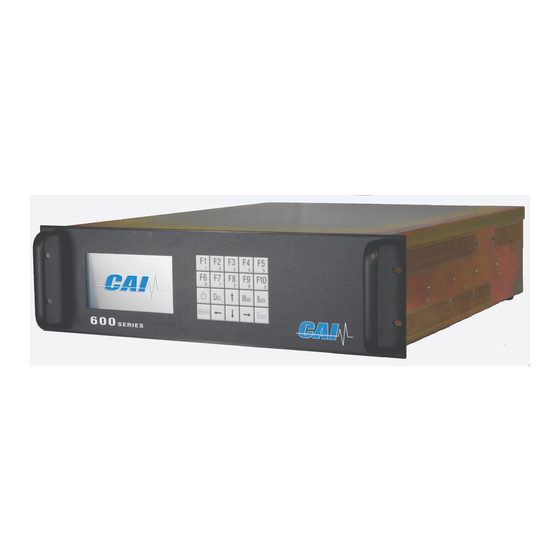
CAI 600 Series User Manual (153 pages)
Total Hydrocarbon Analyzer
Brand:
CAI
| Category:
Measuring Instruments
| Size: 7 MB
Table of Contents
Table of Contents
6
Introduction
16
Overview
16
Unpacking Instructions
16
Reporting Damage
16
Contact Information
16
Warranty Certificate
17
Possible Explosion Hazard
19
Electrical Shock Hazard
19
Fuel Requirements
19
Potential Sample Pump Damage
19
Removing Protective Caps
20
Features
21
Description
21
Features-General
21
Ranges
22
Calibration
22
Manual Calibration
22
Auto Calibration
23
Model 600 MHFID Specifications
24
Installation
25
General
25
Site and Mounting
25
Electrical
26
Figure 3-1 AC Power Switch, Connector, and Fuse
26
Figure 3-2 EMI Suppressor
27
Sampling System
28
Required Gases and Gas Handling Equipment
28
Gas Connections
28
Sampling Requirements
29
Filtration
29
Condensation
29
Presence of Corrosive Gases
29
Gas Temperature
29
Pressure and Flow Rates
29
Sample Gas Bypass Outlet Vent (1) and Exhaust Port (2)
31
Figure 3-3 Sample Gas Bypass Outlet Vent (1) and Exhaust Port (2)
31
Basic Operation
32
Applied AC Power
32
Menu Overview
32
Alarms
33
Deviations
34
Calibration
34
Display (Measurement Screen)
34
Figure 4-1 Measurement Screen
35
Keypad
36
Operation with the Selector Bar and the Arrow Keys
36
Operation with the Function Keys
36
Enter Key
36
Figure 4-2 Keypad
36
Password and Operating Level Menu Structure
37
Operating Levels
37
Password Level Menu
37
User Functions (Level 1)
38
Advanced User Functions (Level 2)
38
Maintenance Functions (Level 3)
38
System User Functions (Level 4)
38
Selection of an Operation Level and Entering a Password
39
Figure 5-1 Enter / Change Password
39
F1 Enter Password
40
Figure 5-2 Access Level Screens
40
Figure 5-3 Enter Password
40
F2 Change Password
41
F3 Reset Passwords
41
Figure 5-4 Passwords
41
Figure 5-5 Reset Passwords to Factory Defaults
41
Available Menus with Access Levels
42
Main Menu
42
F4 Calibrations
43
F5 Setup Menu
45
Menus
47
Figure 6-1 Main Menu on Power up Screen
47
Figure 6-2 Main User Menu (Level 4)
47
Main Menu Tree
48
Figure 6-3 Main Menu
48
F1 Measurement Menu Tree
49
Figure 6-4 Measurement Menu Tree
49
Figure 6-5 Changing the Ranges
50
F4 Calibrations Menu Tree
51
Figure 6-6 Calibration Menu
51
F5 Setup Menu Tree
52
Figure 6-7 Setup Menu
52
Figure 6-8 Setup Menu Tree
53
F5 Password Menu Tree (Sub Menu of F5 Setup)
54
Figure 6-9 Password Menu Tree
55
Menu Function Descriptions
56
F1 Measurements Menu
56
Figure 7-1 Main Menu Screen to Measurement Screen
56
Figure 7-2 Dual F2 Screen
56
Measurement) F3 Diagnostics
57
Figure 7-3 Main Menu Screen to Measurement Screen
57
Figure 7-4 First Diagnostics Screen
57
Figure 7-5 Second Diagnostics Screen
57
Measurement) F4 C1/C3
58
Measurement) F5 Toggle Zero
58
Measurement) F6 Toggle Span
58
Figure 7-6 F4 C1/C3 Selection
58
Figure 7-7 F5 Toggle Zero Selection
58
Measurement) F7 Standby
59
Measurement) Select Range
59
Figure 7-8 Toggle Span Selection
59
Figure 7-9 F7 Go to Standby
59
Figure 7-10 Analyzer Set to Range 1
60
Figure 7-11 Analyzer Set to Range 2
60
Figure 7-12 Analyzer Set to Range 3
60
Figure 7-13 Analyzer Set to Range 4
60
Figure 7-14 Set to Auto-Range
60
F3 Diagnostics
61
F4 Calibrations Set up
61
Entering the Span Gas Concentration
61
Figure 7-15 Diagnostic Screens
61
Selecting the Path for Calibration Gas Introduction
62
Selecting the Range to be Calibrated
62
F2 Automatic Calibration
62
Setting the Analyzer's Internal Clock and Calendar
62
Defining the Calibration Schedule
64
Defining the Ranges to be Calibrated
64
Enabling the Autocalibration Sequence
64
Entering the Automatic Calibration Span Gas Concentration
65
Calibration Gas Introduction/Automatic Calibration Sequence
65
Setting of Automatic Calibration Times
66
Measuring Deviations
66
Figure 7-16 Auto Calibration Cycle
66
Deviations
67
Manual Calibration
67
Zero Calibration
67
Span Calibration
67
Calibration Verification (Manual Mode)
67
Calibrations) F4 Check Calibration
68
Figure 7-17 F4 Check Calibration
68
Calibrations) F5 Reset Calibration Values
69
Figure 7-18 F5 Reset Calibration Values
69
Figure 7-19 Reset Calibration Values
69
Figure 7-20 Reset Calibration Values Confirmation
69
Calibrations) F6 Calibration Range Selection
70
Figure 7-21 Range 1 Selection from Calibrations Menu
70
Figure 7-22 Range 2 Selection from Calibrations Menu
70
Figure 7-23 Range 3 Selection from Calibrations Menu
70
Figure 7-24 Range 4 Selection from Calibrations Menu
71
Figure 7-25 Auto Range Selection from Calibrations Menu
71
F3 Display Deviations
72
Zero Gas Deviations
73
Figure 7-26 F3 Display Deviations
73
Figure 7-27 Zero Gas Deviations
73
Span Gas Deviations
74
Verifying Deviations Zero
74
Figure 7-28 Span Gas Deviations
74
Figure 7-29 Verifying Zero Gas Deviations
74
Verifying Deviations Span
75
Figure 7-30 Verifying Span Gas Deviations
75
F5 Setup
76
Entering the Span Gas Concentration
76
Figure 7-31 Main Menu (User Level 4)
76
Figure 7-32 Setup Menu 1
76
Figure 7-33 Span Gas Concentrations
76
Figure 7-34 Change Span Gas Settings
76
F2 Calibration Settings
77
F1 Times
77
F2 Measuring Deviations
77
Figure 7-35 Change Auto Calibration Settings
77
Figure 7-36 Setup-Times
77
Figure 7-37 Measuring Deviations
78
F3 Deviations
79
F4 Calibrations Via Valves/Probe
80
Figure 7-38 Absolute Versus Relative Deviations
80
Figure 7-39 Calibrations Via Internal Solenoid Valves
80
Figure 7-40 Calibration Via Probe
80
F3 Range Limits
81
Setting Full Scale Range Values
81
Auto Range Switching Levels
81
Figure 7-41 Change Range Limits
81
Figure 7-42 Change Upper Range Limits
81
Figure 7-43 Change Auto Range Limits
81
Alarms
82
F1 Temperatures and Concentration Alarms (T/C Alarms)
82
F2 Pressure Alarms
82
Figure 7-44 Setup Alarms
82
Figure 7-45 Set Temperature Alarms
82
Figure 7-46 Select Set Pressure Alarms
83
F3 EPC Coil Alarms
84
F5 Password
84
Figure 7-47 Select Set EPC Coil Alarms
84
F6 Linearization
85
Change Linearization Coefficients
85
Figure 7-48 Change Linearization Coefficients Screen
85
Figure 7-49 Select Range/Linear Coefficients
85
Display Raw Value
86
F7 System Settings
86
Figure 7-50 F2 Display Raw
86
Figure 7-51 F7 System Setup Screen
86
Real Time Clock
87
System Setup F1 Real Time Clock
87
Figure 7-52 Setup RTC
87
Figure 7-53 Set Autocalibration Cal Timing
87
Figure 7-54 F4 Autocalibration Status
87
F2 TCP/IP Settings
88
F3 Output Assignment
88
Figure 7-55 TCP/IP Address
88
F4 Output Range
89
F5 Status Line ON/OFF
89
F7 Autostart
89
Figure 7-56 Status Line On/Off
89
Figure 7-57 Autostart
89
F8 Measure Settings
90
Figure 7-58 Menu Settings Screen
90
Figure 7-59 Set Time Constant
90
F10 Version
91
Figure 7-60 Analyzer Information/Version
91
Figure 7-61 Device/Software Version
91
F6 Remote / Manual Control
92
F7 Standby
92
Figure 7-62 Remote Manual Control
92
Figure 7-63 Standby Selection
92
Figure 7-64 Standby Screen
92
F8 Ignition
93
Figure 7-65 Ignition
93
Functional Description
94
Operating Principle
94
Burner Assembly
94
Flow System
94
Sample Supply
95
Analyzer Components
96
Rear Panel
96
Figure 9-1 Rear Panel
96
Internal Component Locations
97
Model 600 MHFID Interior Layout
97
Figure 9-2 Interior Layout by Section
97
Model 600 MHFID Electronics Section
98
Model 600 MHFID Solenoid Layout
99
Figure 9-3 Model 600 MHFID Interior Layout
99
Oven Compartment Layout
101
Figure 9-4 Model 600 MHFID Oven Compartment (Full View)
101
Figure 9-5 Oven Compartment (Close Up)
102
Operation
103
Startup
103
Shutdown Procedure
104
Troubleshooting
105
Troubleshooting-Disassembly Procedures
105
Oven Burner Assembly Filter Unit/Filter Removal
105
Flow System/Fuel and Burner Air Supply
105
Troubleshooting Guide
106
Error Messages
107
Glossary
108
Abs Deviations
108
Calibration Via Probe
108
Calibration Via Solenoid Valves
108
Change Linear Coefficients
108
Linear Curve: Standard FACTORY
108
Lin. Value
108
Measured Curve
108
Measuring Deviation
108
Measured Value
108
Physical Range (AKA Linear Curve)
109
Purge / Calibration / Verifying Purge after
109
Purge: (MAIN MENU)
109
Real Time
109
Raw Value
109
Relative Deviations
109
Reset Calibration Values
109
Software Range (AKA Measurement Curve)
109
Status Line
109
AK Protocol Format
110
Serial Interface and AK-Commands
110
Interface Parameters
110
General AK Requirements
111
Scans
111
AKON: Measured Concentration Value
111
AEMB: Set Measuring Range
111
AMBE: Measuring Range Limit
111
AKAK: Calibration Gas Concentrations
112
AMBU: Upper and Lower Range Switchover Values for Auto Range
112
ASTZ: Normal Device Status
112
Possible States
112
ASTF: Error Status
113
AKEN: Device Identification
113
ARMU: Raw Value
113
ATEM: Temperatures
113
ADRU: Pressures
113
ADUF: Flows
114
AGRD: Polynom Coefficients
114
AANG: Deviation from Zero Point after Autocalibration
114
AAEG: Deviation from End Point after Autocalibration
114
AFDA: Purge and Autocalibration Times
114
APAR: Request Autocalibration Tolerance Values
114
AKAL: Deviations from Calibration
115
ASYZ: Respond System Time
115
AT90: Respond Lowpass Filter Time
115
ADAL: Diagnostic Alarm Limits
115
ACXB: Respond Display Factor
115
Control Commands
116
SRES: Reset
116
SPAU: Pause
116
STBY: Standby
116
SNGA: Open Valve for Zero Gas Calibration
116
SEGA: Open Valve for End Gas Calibration
116
SSPL: Purge Analyzer with Zero Gas
116
SLIN: Linearization Mode
116
SATK: Start Automatic Calibration
116
SEMB: Set Measuring Range
116
SARE: Auto Range on
117
SARA: Auto Range off
117
SREM: Remote Mode for AK-Commands
117
SMAN: Manual Control to Control Device Manually
117
SMGA: Start Measuring
117
SNKA: Saves Measured Value as New Offset
117
SEKA: Saves Measured Value as New Span Value
117
SHCG: Cutter off
117
SCH4: Cutter on
117
Settings
118
EKAK: the Four Span Gas Concentration Values Are Set
118
EMBE: the Four Measuring Range End Values Are Set
118
EMBU: the Upper and the Lower Range Switchover for Autorange Are Set
118
EKEN: Set New Device Identification
118
EGRD: Set Polynom Coefficients
118
EFDA: Set Autocalibration and Purge Times
118
EPAR: Set Autocalibration Tolerance Values
118
ESYZ: Set System Time
119
ET90: Set Lowpass Filter Time
119
EDAL: Diagnostic Alarm Limits
119
ECXB: Set Display Factor
119
Abbreviations Used
119
Appendix
120
Connectors
120
Main Connector (Standard 28 Pin Connector)
120
Auxiliary Connector (Standard 28 Pin Connector)
120
Advertisement
CAI 600 Series User Manual (110 pages)
CLD/O2
Brand:
CAI
| Category:
Analytical Instruments
| Size: 3 MB
Table of Contents
Table of Contents
3
1 Introduction
10
Overview
10
Unpacking Instructions
10
Reporting Damage
10
Contact Information
10
Warranty Certificate
11
2 Features
12
Description
12
Features-General
12
Model 650 Cld/Paramagnetic Specifications
13
3 Installation
14
General
14
Site and Mounting
14
Electrical
15
Figure 3-1 AC Power Switch, Connector, and Fuse
15
Figure 3-2 EMI Suppressor
15
Analog Output Connections
16
Gases
16
Gas Handling Equipment
16
Gas Connections
16
Sampling Requirements
17
Filtration
17
Condensation
17
Presence of Corrosive Gases
17
Gas Temperature
17
Pressure and Flow Rates
17
4 Basic Operation
18
Display
18
Figure 4-1 Measurement Screen
18
Menu Tree
19
Keyboard
22
Operation with the Cursor Keys and the Enter Key
22
Operation with the Function Keys
22
Read/Change Parameters
22
Figure 4-2 Keyboard
22
5 Operating Structure
23
The Main Menu
24
Figure 5-1 Main Menu on Power up Screen
24
Figure 5-2 Main User Menu (Level 4)
24
6 Menu Structure
25
User Functions (Level 1)
25
Advanced User Functions (Level 2)
25
Maintenance Functions (Level 3)
25
System User Functions (Level 4)
25
7 Main Menu Function Descriptions
26
F1 Measurements
26
F1 no or no
26
Measurement
26
Figure 7-1 Main Menu Screen
26
Figure 7-2 Measurements Screen
26
F2 no + no
27
Measurement
27
F3 Diagnostics
27
Figure 7-3 Measurement Screen
27
Figure 7-4 First Diagnostics Screen
27
Figure 7-5 Second Diagnostics Screen
27
Select Range
28
F2 Purge Analyzer
28
Figure 7-6 Set to Auto-Range
28
Figure 7-7 Analyzer Set to Range 3
28
Figure 7-8 Main Menu (User Level 4)
28
Figure 7-9 Purge Screen
28
F3 Diagnostics
29
F4 Calibrations
29
Figure 7-10 Main User Menu (Level 4)
29
Figure 7-11 Main User Menu (Level 4)
29
Figure 7-12 Calibration Screen (Level 4)
29
F1 Automatic Calibration
30
Figure 7-13 Auto Calibration Screen
30
F2 Manual Calibration
31
Figure 7-14 F2 Manual Calibration
31
Figure 7-15 Manual Calibration Screen
31
Figure 7-16 Manual Zero Gas Calibration
31
Figure 7-17 Manual Span Gas Calibration
31
Figure 7-18 Range Select
32
Figure 7-19 Selected Range 1
32
Figure 7-20 Selected Range 2
32
Figure 7-21 Selected Range 3
32
Figure 7-22 Selected Range 4
32
Figure 7-23 Selected Auto Range
32
F3 Display Deviations
33
Figure 7-24 F3 Display Deviations
33
Figure 7-25 Display Deviations Screen
33
Absolute Span Gas Deviation
34
Absolute Zero Gas Deviation
34
Figure 7-26 Zero Gas Deviations
34
Figure 7-27 Zero Gas Deviations Verifying
34
Figure 7-28 Span Gas Deviations
34
Figure 7-29 Span Gas Deviations Verifying
34
Relative Span Gas Deviation
34
Relative Zero Gas Deviation
34
F4 Check Calibration
35
F5 Reset Calibration Values
35
F6 Range Select
35
Figure 7-30 F4 Check Calibration
35
Figure 7-31 Check Calibration
35
Figure 7-32 F5 Reset Calibration Values
35
Figure 7-33 Reset Calibration Values
35
Figure 7-34 Range Select
35
Figure 7-35 Range
35
F5 Setup
36
Figure 7-36 Main Menu (User Level 4)
36
Figure 7-37 Setup Menu 1
36
Figure 7-38 Setup Menu 2
36
F1 Span Gas Concentration
37
F2 Calibration Settings
37
Figure 7-39 Change Span Gas Settings
37
Figure 7-40 Change Auto Calibration Settings
37
F1 Times
38
F2 Measuring Deviations
38
F3 Deviations
38
Figure 7-41 Setup-Times
38
Figure 7-42 Measuring Deviations
38
Figure 7-43 Absolute Versus Relative Deviations
38
F3 Range Limits
39
F4 Calibrations Via Solenoids
39
F5 Calibration Via Probe
39
Figure 7-44 Calibrations Via Internal Solenoid Valves
39
Figure 7-45 Calibration Via Probe
39
Figure 7-46 Change Range Limits
39
F1 Range 1-4 (Change Upper Range Limits)
40
F2 Change Auto Range Limits
40
Figure 7-47 Change Upper Range Limits
40
Figure 7-48 Change Auto Range Limits
40
Alarms
41
Figure 7-49 Set Temperature Alarms
41
Figure 7-50 Set Concentration, Pressure and Voltage Alarms
41
Figure 7-51 Enter / Change Password
41
Password
41
F1 Enter Password
42
F2 Change Password
42
F3 Reset Passwords
42
Figure 7-52 Access Level Screen
42
Figure 7-53 Passwords
42
F7 System Settings
43
Figure 7-54 Linearization Screen
43
Figure 7-55 Coefficients Range Select
43
Figure 7-56 Linearization Coefficients
43
Figure 7-57 Range Raw Data with F2
43
Figure 7-58 System Settings
43
Figure 7-59 System Setup Screen
43
Linearization
43
F1 Real Time Clock
44
F2 Set Autocalibration Time
44
Figure 7-60 Clock and Timing Setup Screen
44
Figure 7-61 Set Clock Screen
44
Figure 7-62 Select Autocalibration Time
44
Figure 7-63 Set Autocalibration Cal Timing
44
Auto Calibration
45
F3 Set Auto Cal Ranges
45
F4 Autocalibration On/Off
45
Figure 7-64 Clock and Timing Setup Screen
45
Figure 7-65 F4 Toggles Auto Cal on of off
45
Figure 7-66 Autocalibration Status
45
F2 Displays TCP/IP Address
46
F3 Displays Output Signal Assignments
46
F4 Displays Output Ranges
46
Figure 7-67 TCP/IP Address
46
Figure 7-68 Output Assignments
46
Figure 7-69 Output Ranges
46
F5 Turns Status Line on or off
47
F8 Measure Settings
47
Figure 7-70 Status Line
47
Figure 7-71 Menu Settings Screen
47
Figure 7-72 Set no
47
Set no
47
F2 Converter Efficiency
48
F4 Purge Time
48
Figure 7-73 Set Converter Efficiency
48
Figure 7-74 Set Time Constant
48
Figure 7-75 Set Purge Time
48
Low Pass Filter Time Constant
48
F10 Displays the Current Analyzer and Software Versions
49
Figure 7-76 Analyzer Information Version
49
Figure 7-77 Software Version
49
F7 Remote / Manual Control
50
F8 Standby
50
Figure 7-78 Remote Manual Control
50
Figure 7-79 Standby Selection
50
Figure 7-80 Standby Screen
50
8 Analyzer Components
51
Rear Panel
51
Main Connector (Standard 28 Pin Connector)
52
Auxiliary Connector (Standard 28 Pin Connector)
52
Digital Outputs - RS-232 (Standard 9 Pin DIN Connector)
52
Digital Outputs - TCP/IP (8 Pin RJ-47 Connector)
53
Internal Component Locations
54
Figure 8-1 Major Internal Components
54
Main Electronics Board (Potentiometers)
55
Main Electronic Board Potentiometers
55
Main Electronics Board (Connectors)
56
Main Electronic Board Connectors
56
Reaction Chamber
57
Figure 8-2 Reaction Chamber Pre-Amplifier
57
Relay Board Connections
58
Figure 8-3 Relay Board Connections
58
9 Operation
59
Preparation for Operation
59
Shut down Procedure
60
10 Functional Description
61
10.1. Operating Principle- NO/NO
61
Reaction Chamber
61
Flow System
61
Main Electronics Board
61
Relay Board
61
10.2. Principle of Operation-Oxygen
62
Figure 10-1 Magnetic Susceptibility of Gases
62
Figure 10-2 the Measuring Cell in Theory
62
Figure 10-3 Principle of Operation
63
Cross Sensitivity of Gases
64
Table 10-1 Cross Sensitivity of Gases
65
11 Reaction Chamber Servicing
66
Disassembly Procedure
66
Assembly Procedure
66
12 Troubleshooting
67
Ozone Air/O Supply
67
Sample Supply
67
NO Converter
67
13 AK Protocol Format
68
13.1. Serial Interface and AK-Commands
68
Interface Parameters
68
13.3. General AK Requirements
69
Scans
69
Control Commands
76
Settings
79
Abbreviations Used
81
CAI 600 Series User Manual (86 pages)
Gas Analyzer
Brand:
CAI
| Category:
Measuring Instruments
| Size: 3 MB
Table of Contents
Table of Contents
5
1 Introduction
14
Overview
14
Unpacking Instructions
14
Reporting Damage
14
Contact Information
14
Warranty Certificate
15
Possible Explosion Hazard
16
Electrical Shock Hazard
16
Plug Removal
16
2 Features
17
Description
17
Features-General
17
Infrared Gas Analyzers
18
Figure 2-1 Single NDIR Analyzer
18
Interference Gases
19
Figure 2-2 Detector Output Signal
19
Figure 2-3 Absorption Characteristic of Detector
19
Electronics
20
Figure 2-4 Block Diagram
20
Model 600 NDIR Specifications
21
Model 600 NDIR Features
21
3 Installation
22
General
22
Site and Mounting
22
Electrical
22
Figure 3-1 AC Power Switch, Connector, and Fuse
22
Analog Output Connections
23
Gases
23
Gas Handling Equipment
24
Gas Connections
24
Sampling Requirements
24
Filtration
24
Condensation
24
Presence of Corrosive Gases
24
Gas Temperature
24
Sample Gas Bypass Outlet (Vent)
24
4 Basic Operation
25
Display
25
Figure 4-1 LCD Display
25
Menu Trees
26
Keyboard
29
Operation with the Cursor Keys and the Enter Key
29
Operation with the Function Keys
29
Read/Change Parameters
29
Figure 4-2 Keyboard
29
5 Operating Structure
30
The Main Menu
31
Figure 5-1 Main Menu on Power up Screen
31
Figure 5-2 Main User Menu (Level 4)
31
6 Menu Structure
32
User Functions (Level 1)
32
Advanced User Functions (Level 2)
32
Maintenance Functions (Level 3)
32
System User Functions (Level 4)
32
7 Main Menu Function Descriptions
33
F1 Measurements
33
F1 Measurement
33
Figure 7-1 Main Menu Screen
33
Figure 7-2 Measurements Screen
33
Range Select
34
Figure 7-3 Set to Auto Range (601)
34
Figure 7-4 Analyzer Set to Range 1 (603)
34
F2 Purge Analyzer
35
F3 Diagnostics
35
Figure 7-5 Main Menu (User Level 4)
35
Figure 7-6 Purge Screen
35
Figure 7-7 Diagnostics Screen I
35
F4 Calibrations
36
F1 Automatic Calibration
36
Figure 7-8 Calibration Screen
36
Figure 7-9 Auto Calibration Screen
36
F2 Manual Calibration
37
Figure 7-10 Manual Calibration
37
Figure 7-11 Manual Zero Calibration
37
Figure 7-12 Manual Span Calibration
37
Display Deviations - from Calibration Menu F3
38
Absolute Zero Gas Deviation
38
Relative Zero Gas Deviation
38
Figure 7-13 Display Deviations
38
Figure 7-14 Zero Gas Deviations
38
Figure 7-15 Span Gas Deviations
38
Absolute Span Gas Deviation
39
Relative Span Gas Deviation
39
F4 Check Calibration
39
F5 Reset Calibration Values
39
F6 Range Select
39
F5 Setup
40
F1 Span Gas Concentration
40
Figure 7-16 Setup Menu Screen I
40
Figure 7-17 Setup Menu Screen II
40
Figure 7-18 Change Span Gas Settings
40
Calibration Settings
41
F1 Times
41
F2 Measuring Deviations
41
F3 Deviations
41
F3 Range Limits
41
Figure 7-19 Change Auto Calibration Settings
41
Figure 7-20 Change Range Limits
41
F1 Range 1-4 (Change Upper Range Limits)
42
F2 Change Auto Range Limits
42
Figure 7-21 Change Upper Range Limits
42
Figure 7-22 Change Auto Range Limits
42
F4 Alarms
43
F5 Password
43
Figure 7-23 Alarm Screen I
43
Figure 7-24 Alarm Screen II
43
Figure 7-25 Enter / Change Password
43
F1 Enter Password
44
F2 Change Password
44
F3 Reset Passwords
44
Figure 7-26 Access Level Screen
44
F6 Linearization
45
Figure 7-27 Linearization Screen
45
Figure 7-28 Coefficients Range Select
45
Figure 7-29 Change Coefficients
45
Figure 7-30 Linearized and Raw Data
45
F7 System Settings
46
F1 Real Time Clock
46
Figure 7-31 System Setup Screen
46
Figure 7-32 Clock and Timing Setup Screen
46
Figure 7-33 Clock Set Screen
46
Figure 7-34 Set Auto Cal Timing
47
Figure 7-35 Set Auto Cal Ranges
47
Figure 7-36 F4 Toggles Auto Cal on of off
47
System Setup F2 Displays TCP/IP Address
48
Systems Setup F3 Displays Output Signal Assignments
48
System Setup F4 Displays Output Ranges
48
Figure 7-37 TCP/IP Address
48
Figure 7-38 Output Assignments
48
Figure 7-39 Output Ranges
48
F5 Turns Status Line on or off
49
F8 Measure Settings
49
F1 Set Lowpass Filter
49
Figure 7-40 Status Line
49
Figure 7-41Status Line On/Off
49
Figure 7-42 Measure Setup
49
Figure 7-43 Lowpass Filter
49
F2 Purge Time
50
F3 Set Temperature Compensation
50
F4 Pressure Compensation
50
F3 Low Pass Filter Time Constant
50
Figure 7-44 Purge Time
50
Figure 7-45 T-Compensation
50
Figure 7-46 P-Compensation
50
F10 Displays the Current Analyzer and Software Versions
51
F7 Remote / Manual Control
51
Figure 7-47 Low Pass Filter Time Constant
51
Figure 7-48 Analyzer Information
51
Figure 7-49 Software Version
51
Figure 7-50 F6 Remote/Manual
51
F8 Standby
52
Figure 7-51 F7 Standby
52
Figure 7-52 Standby Mode
52
8 Analyzer Components
53
Rear Panel
53
Rear Panel Connectors
54
Digital Outputs
55
RS-232 (Standard 9 Pin DIN Connector)
55
TCP/IP (8 Pin RJ-47 Connector)
55
Internal Component Locations
56
Figure 8-1 Internal Components
56
Main Electronics Board (Potentiometers)
57
Figure 8-2 Main Electronic Board Potentiometers
57
NDIR Detector Assembly
58
Figure 8-3 NDIR Detector Assembly
58
9 Operation
59
External Wiring
59
External Piping
59
Operation & Calibration
59
Power on
59
Zero/San Adjustment
59
Start-Up and Routine Maintenance
59
10 Maintenance
60
Zero and Span Calibration
60
Cleaning of the Optical Bench Measuring Cell (Infrared Analyzers Only)
60
Optical Bench Configuration
60
Table 10-1 Optical Bench Configuration
60
Figure 10-1 Optical Bench with Pipe Sample Cell
61
Removal of Pipe Cell
62
Figure 10-2 Optical Bench with Block Sample Cell
63
Removal of Block Cell
64
Figure 10-3 Optical Bench with Pipe and Block Type Sample Cells
65
Disassembly of Combination Pipe & Block Type Cells
66
11 Adjustments Checks and Repairs
68
Adjustment of Detector Voltage (NDIR'S Only)
68
11.2. Coarse Zero Adjustment
68
11.3. Span Gain Adjustment
68
11.4. Check and Repair Detector
69
Problem
69
Symptom
69
Check And/Or Replace
69
11.5. Check and Repair Infrared Light Source Unit
70
Problem
70
Symptom
70
Check And/Or Replace
70
Check and Replace Chopper
70
11.7. Check and Repair Measuring Cell
71
Problem
71
Symptom
71
Check and or Replace
71
11.8. Check and Repair Tubing Trouble
71
11.9. Check and Repair Amplifier Circuit
72
Figure 11-1 Amplifier Circuit Ac Wave Form
72
12 Communication Master Computer / Analyzer (AK Protocol)
73
Serial Interface and AK-Commands
73
Interface Specifications
73
Figure 12-1 Serial Interface
73
Protocol Description
74
Instruction Command
74
Acknowledgement Command
74
Table 12-1 Structure of an Instruction Command
74
Table 12-2 Structure of an Acknowledgement Command
74
Data Description
75
Error Handing
75
Table 12-3 Acknowledgment Response in Case of Error
75
Scan Commands
76
AKON: Measured Concentration Value
76
AEMB: Get Measuring Range
76
AMBE: Measuring Range Limit
76
AKAK: Calibration Gas Concentrations
76
AMBU: Upper and Lower Range Switchover Values for Auto Range
76
ASTZ: Normal Device Status
77
ASTF: Error Status
77
AKEN: Device Identification
77
ARMU: Raw Value
77
ATEM: Temperatures
78
ADRU: Pressures/ Valve Voltage
78
ADUF: Flows
78
AGRD: Polynom Coefficients
78
AANG: Deviation from Zero Point after Autocalibration
78
AAEG: Deviation from End Point after Autocalibration
78
AFDA: Purge and Autocalibration Times
78
APAR: Request Autocalibration Tolerance Values
79
AVER: Query Software Version
80
Control Commands
81
SARE: Auto Range on
82
Settings
83
ESYZ: Set System Time
84
EUDP Set UDP Data Streaming Parameters
85
Advertisement
CAI 600 Series User Manual (115 pages)
CLD
Brand:
CAI
| Category:
Measuring Instruments
| Size: 5 MB
Table of Contents
Table of Contents
5
1 Introduction
9
Overview
9
Unpacking Instructions
9
Reporting Damage
9
Contact Information
9
Warranty Certificate
10
2 Features and Specifications
11
Descriptions
11
Features
11
Specifications
11
3 Installation
13
General
13
Site and Mounting
13
Electrical
13
Outputconnections
14
Gas Handling Equipment
14
Gas Connections
14
Sampling Requirements
15
Filtration
15
Condensation
15
Presence of Corrosive Gases
15
Gas Temperature
15
Sample Gas Outlet
15
4 Basic Operation
15
Display
16
Menu Tree
17
Keyboard
18
Operation with Function Keys
18
Read and Change Parameters
18
5 Operating Structure
19
Main Menu
21
6 Menu Structure
21
User Functions (Level 1)
21
Advanced User Functions (Level 2)
21
Maintenance User Functions (Level 3)
21
System User Functions (Level 4)
21
7 Main Menu
22
F1 Measurements
22
F1 no or Nox Measurement
22
F2 no + NO2 Measurement
22
F3 Diagnostics
23
F2 Purge Analyzer
25
F3 Diagnostics
25
F4 Calibrations
26
F1 Automatic Calibration
26
F2 Manual Calibration
27
F3 Display Deviations
28
F5 Reset Calibration Values
29
F6 Range Select
29
F5 Setup
30
F1 Span Gas Concentrations
31
F1 Times
31
F2 Calibration Settings
31
F1 Change Upper Range Limits
32
F2 Measuring Deviations
32
F3 Deviations
32
F3 Range Limits
32
F4 Calibration Via Valves
32
F5 Calibration Via Probe
32
F2 Change Auto Range Limits
33
F5 Password
34
F1 Enter Password
34
F2 Change Password
34
F3 Reset Passwords
35
F6 Linearization
35
F7 System Settings
36
F2 TCP/IP Address
38
F3 Output Signal Assignments
38
F4 Output Ranges
38
F7 Automatic Setup
39
F8 Measure Settings
40
F3 Set Time Constant
41
F8 Standby
42
8 Analyzer Components
43
Internal Components
46
Main Electronics Board (Potentiometers)
47
Main Electronics Board (Connections)
48
Reaction Chamber
49
Relay Board Connections
50
9 Operation
51
Preparation
51
Shut down Procedure
52
10 Functional Description
53
Operating Principle
53
Reaction Chamber Assembly
53
Flow System
53
Main Electronics Board
54
Relay Board
54
Reaction Chamber Disassembly
54
Reaction Chamber Assembly
54
12 Troubleshooting
55
Ozone Air/O2 Supply
55
Sample Supply
55
No/Nox Converter
55
AK Protocol
55
13 Appendix 1
56
Introduction
76
Addendum Starting after June, 2007
93
Operation of Measurement Keys
94
Over Range
94
Zero
94
Range Limits
96
Span Values
96
New Functions
98
Auto Start up
98
Alarms On/Off
99
Offset & Gain
100
Calibrate the Analog Outputs
100
Save Data Archiving Time
104
User Digital Outputs
106
Cal Analog Output
110
Changes to Existing Functions
111
Saved or Outside Limits
111
Calibration Deviations
112
Flow Zero or Span Gas
112
Reset Calibration Values
113
Advertisement
Related Products
CAI 600-NDIR
CAI 650 Series
CAI 700 CLD Series
CAI 700 HCLD NOX Series
CAI 700 LX Series
CAI 700 NDIR
CAI 700 Series
CAI 700M
CAI 750
CAI 750 CLD
CAI Categories
Measuring Instruments
Stereo System
Indoor Furnishing
Analytical Instruments
Ladders
More CAI Manuals
Login
Sign In
OR
Sign in with Facebook
Sign in with Google
Upload manual
Upload from disk
Upload from URL