Table of Contents
Advertisement
Quick Links
Chevrolet Spark 2013-up
KIT FEATURES
• ISO DIN radio provision with pocket
• Double DIN radio provision
• Interface included retains factory OnStar, Bluetooth, and
all warning chimes
• Provides a 12-volt accessory power and VSS, parking
brake, and reverse signals
• Painted matte black
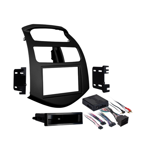
KIT COMPONENTS
• A) Radio trim panel • B) Radio brackets • C) Pocket • D) (4) #8 x 3/8" Phillips screws • E) (10) White plastic
panel clips • F) Interface • G) 16-pin harness • H) 4-pin to 4-pin resistor pad • I) 22-pin to 44-pin harness
A
B
F
Installation instructions for 99-3309B
APPLICATIONS
See application list inside
99-3309B
C
D
G
E
H
I
WIRING & ANTENNA CONNECTIONS (sold separately)
Wiring Harness:
• Interface included
Antenna Adapter:
• 40-EU55
TOOLS REQUIRED
• Panel removal tool • Phillips screwdriver
• Small flat-blade screwdriver
CAUTION: Metra recommends disconnecting the
negative battery terminal before beginning any
installation. All accessories, switches, and especially
air bag indicator lights must be plugged in before
reconnecting the battery or cycling the ignition.
NOTE: Refer to the instructions included with the
aftermarket radio.
Advertisement
Table of Contents

Related Manuals for Metra Electronics 99-3309B


Summary of Contents for Metra Electronics 99-3309B
- Page 1 Installation instructions for 99-3309B APPLICATIONS See application list inside WIRING & ANTENNA CONNECTIONS (sold separately) Chevrolet Spark 2013-up Wiring Harness: 99-3309B • Interface included Antenna Adapter: KIT FEATURES • 40-EU55 • ISO DIN radio provision with pocket • Double DIN radio provision • Interface included retains factory OnStar, Bluetooth, and all warning chimes • Provides a 12-volt accessory power and VSS, parking TOOLS REQUIRED brake, and reverse signals • Panel removal tool • Phillips screwdriver • Painted matte black •...
- Page 2 99-3309B Dash Disassembly 99-3309B Chevrolet Spark 2013-up 1. Unclip and remove the radio trim panel. (Figure A) 2. Remove (4) Phillips screws securing the factory radio and remove from dash. (Figure B) 3. Unclip and remove the vents from the factory panel. (Figure A) (Figure B) (Figure C) 4. Unclip and remove the hazard button from the trim Step 5 panel. (Figure C) Step 5 5. Remove (5) Phillips screws Step 3 securing the upper display shroud from the factory panel. (Figure C) Step 4...
- Page 3 Kit Assembly 99-3309B ISO DIN radio provision with pocket 1. Attach the factory vents and hazard button to the Metra trim panel. (Figure A) 2. Attach the upper display shroud the Metra trim panel with the factory Step 2 screws. (Figure A) 3. Attach the provided (10) panel clips to the legs of the Metra trim panel. Step 2 4. Locate the factory wiring harness in the dash. Metra recommends using the proper mating adapter from Metra Step 1 or AXXESS. Re-connect the negative battery terminal and test the unit for proper operation. 5. Attach the radio brackets to the aftermarket radio using the screws supplied with the radio, then secure the assembly to the pocket using the (4) #8 x 3/8” Phillips screws. (Figure B) 6. Mount the assembly into the sub-dash.
-
Page 4: Double Din Radio Provision
Kit Assembly 99-3309B Double DIN radio provision 1. Attach the factory vents and hazard button to the Metra trim panel. (Figure A) 2. Attach the upper display shroud the Step 2 Metra trim panel with the factory screws. (Figure A) 3. Attach the provided (10) panel clips to Step 2 the legs of the Metra trim panel. 4. Locate the factory wiring harness in the dash. Metra recommends using Step 1 the proper mating adapter from Metra or AXXESS. Re-connect the negative battery terminal and test the unit for proper operation. 5. Attach the radio brackets to the aftermarket radio using the screws supplied with the radio, then mount the assembly into the sub dash. (Figure B) 6. Reassemble dash in reverse order of disassembly using the Metra trim panel Step 1 instead of the factory trim panel. - Page 5 99-3309B Axxess Interface Installing the interface Installation From the 16-pin harness: • The Green/Black wire is not used in this application. • Connect the Red wires to the ignition/accessory FEATURES The following wires are for the aftermarket radios that wire of the aftermarket radio. • Provides accessory (12-volt 10-amp) have navigation built in: • Connect the Orange/White wire to the • Retains R.A.P. (Retained Accessory Power) • Connect the Light Green wire to the parking brake illumination wire of the aftermarket radio. If the • Used in amplified or non-amplified systems wire of the aftermarket navigation radio. aftermarket radio has no illumination wire, tape off • Retains all warning chimes the Orange/White wire. • Connect the Blue/Pink wire to the VSS or speed • Provides NAV outputs (parking brake, reverse, sense wire of the aftermarket navigation radio.
- Page 6 99-3309B Installing the interface Chime volume adjustment • Connect the Green/Black wire to the left rear negative wire of the aftermarket radio. Amplified vehicles: 1) With car on, shut off car and leave keys in • The Pink wire is not used in this application. i gnition. Open the car door and leave it open. • Connect the Violet wire to the right rear positive Chimes will be heard. wire of the aftermarket radio. Installing the interface: 2) Wait 10 seconds, then with a small • Connect the Violet/Black wire to the right rear 1. With all the connections completed, plug the 16 and screwdriver adjust the potentiometer fully negative wire of the aftermarket radio. 22 pin harnesses into the interface. counterclockwise (all the way left), then clockwise • Connect the Green wire to the left rear positive wire 2. Plug the 44 pin GM harness into the vehicle side to raise chime level and counterclockwise to lower of the aftermarket radio.
- Page 7 99-3309B Vehicle customization OnStar level adjustment with optional LCD To adjust the OnStar volume level find the Black/Yellow wire on the 16-pin (AXXESS part # XIA-LCD sold separately) harness. Push the blue OnStar button, while the voice is speaking tap the Black/Yellow wire to ground. Once the volume is set it will stay at that volume The OEM radio is used to customize certain features of the vehicle. until the Black/Yellow wire is tapped to ground again. This can be set during Use the optional LCD to adjust these features accordingly: installation and then left alone. If user adjustment is desired, the customer may also tap “Volume Up” or down on the steering wheel (if equipped) to adjust the 1. Press ESC, and then press ENT: “Set Language” will appear on the screen. OnStar level. 2. To change the language, press ENT, and then press the arrow up and down buttons to change the language. Additional 12-pin harness (ASWC-1) 3. Once you have selected your language, press ESC to go back to the •...
Need help?
Do you have a question about the 99-3309B and is the answer not in the manual?
Questions and answers