Table of Contents
Advertisement
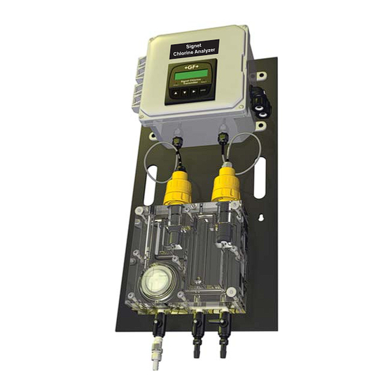
Signet 4630 Free Chlorine Analyzer System
Signet 4632 Chlorine Dioxide Analyzer System
*3-463X.090*
3-4630.090 Rev M 04/15
•
English
Deutsch
•
•
Français
•
Español
The Signet 4630 and 4632 Systems are EPA 334.0 Compliant.
Description
The Signet Chlorine Analyzer Systems are integrated, all-in-one chlorine panel systems
designed to measure Free Chlorine or Chlorine Dioxide in drinking water and clean, fresh
water treatment applications.
This manual includes the 4630 Free Chlorine and 4632 Chlorine Dioxide Analyzer Systems.
Features:
• EPA 334.0 Compliant: The 4630 Free Chlorine and 4632 Chlorine Dioxide systems can
be used for reporting chlorine residuals in accordance with EPA Method 334.0.
• Complete chlorine analyzer system allows quick setup and easy installation. Connect
to a water source and plug it in.
• Unique integrated clear fl ow cell combines sensors, fl ow regulator, fi lter and variable
area fl ow indicator in one compact unit.
• Built-in variable area fl ow indicator facilitates fl ow rate confi rmation at a glance.
• Integrated fl ow regulator with removable fi lter accepts inlet pressures of 1 to 8 bar
(15 to 120 psi) while maintaining constant fl ow and minimal pressure to the sensors.
• Water fl ows vertically into sensor tip, eliminating bubble entrapment. Raised exit in fl ow
cell sensor chamber ensures sensors stay submerged even when system and fl ow is
turned off.
• Flow cell accommodates two sensors; one chlorine and an optional pH sensor.
• Automatic pH and temperature compensation or manual pH value input capability for
accurate free chlorine readings.
• Easy viewing of the transmitter via the bright backlit LCD display.
• Moisture-proof NEMA 4X wiring enclosure.
Additional information can be found in the individual product manuals,
refer to www.gfsignet.com.
Click on Product Manuals under the Signet Quick Links section.
Safety
CAUTION!
1. Follow instructions carefully to avoid personal injury.
2. Do not exceed the maximum pressure or temperature specifi cations.
3. Mounting the Chlorine System in an outdoor box, in areas with elevated temperatures,
may cause damage to the system if the enclosure's internal temperature exceeds the
temperature specifi cation of the Chlorine Analyzer.
4. Do not alter product construction.
5. For use with clean fresh water only.
6. Disconnect AC power before opening wiring enclosure.
7. This panel system uses AC voltages. Wiring should be done by qualifi ed personnel only.
Operating Instructions
English
Advertisement
Table of Contents
Troubleshooting

Subscribe to Our Youtube Channel
Related Manuals for +GF+ Signet 4630


Summary of Contents for +GF+ Signet 4630
-
Page 1: Description
*3-463X.090* 3-4630.090 Rev M 04/15 Operating Instructions The Signet 4630 and 4632 Systems are EPA 334.0 Compliant. Description The Signet Chlorine Analyzer Systems are integrated, all-in-one chlorine panel systems designed to measure Free Chlorine or Chlorine Dioxide in drinking water and clean, fresh water treatment applications. -
Page 2: Table Of Contents
Warranty Information Table of Contents Refer to your local Georg Fischer Sales offi ce for the most Description ................1 current warranty statement. Warranty Information ..............2 Product Registration ..............2 All warranty and non-warranty repairs being returned must Safety Information ..............2 include a fully completed Service Form and goods must be returned to your local GF Sales offi... -
Page 3: Chlorine System Dimensions
Dimensions Specifi cations General 165 mm (6.5 in.) Compatible Signet Sensors: • 3-2630-1 Free Chlorine Sensor 0-2 ppm • 3-2630-2 Free Chlorine Sensor 0-5 ppm • 3-2630-3 Free Chlorine Sensor 0-20 ppm • 3-2632-1 Chlorine Dioxide Electrode 0-2 ppm • 3-2724-00 Flat pH Electrode Materials: Panel: ........ -
Page 4: 4630 Chlorine Analyzer System Inventory
System Inventory Chlorine panel assembly Built-in pressure regulator 15 to 120 psi. 3/8 inch hose barb connectors. 1 each 2630 series Free Chlorine sensor or 2632 Chlorine Dioxide sensor; each with protective cap 1 spare membrane cap 2 bottles of electrolyte solution 1 syringe needle (taped to bottle) 1 syringe 1 each Flat pH sensor 3-2724-00 (159 001 545) (3-4630-11, -21, -31 and 3-4632-11 models only) -
Page 5: Panel Assembly
Panel Assembly Wiring enclosure Transmitter 3-8630-3P (159 001 673) Output conduits Power cable conduit Vent pH sensor Amperometric chlorine electronics sensor electronics 3-2750-7 (159 001 671) 3-2650-7 (159 001 670) Chlorine electrode pH electrode 3-2630-X (Free Chlorine) 3-2724-00 (159 001 545) 3-2632-1 (Chlorine Dioxide) Flow cell block Flow range limits... -
Page 6: Component Identifi Cation: Flow Cell
Component Identifi cation: Flow Cell Flow cell nut Flat washer Flow cell back block Spacer ring Regulator Assembly Stainless steel fi lter (3-4630.391) (159 001 689) Pressure regulator Pressure regulator outer O-ring (large) Flow Cell Rebuild Kit Pressure regulator outer O-ring (small) (3-4630.390) 3-4630.392 (159 001 688) -
Page 7: Mounting
Mounting Do not mount in direct sunlight. • Bright light can promote algae growth. Indoor mounting is recommended. • If the system is mounted outdoors, an outdoor enclosure for the whole system must be used to protect the electronics and fl ow cell from light, rodents, insects and dirt. •... -
Page 8: Wiring Input
Wiring Input Power Supply Terminal Identifi cation WARNING Terminal Name Description This panel system is V. ADJ Voltage Adjusts within ±10%; turning clockwise wired for AC voltages adjustment increases output voltage that can injure or kill. Wiring should be performed by DC ON Operation Green LED is lit when output voltage... -
Page 9: Wiring Output
Wiring Output Follow all local and government recommendations and WARNING methods for installation of electrical connections to and between the system and other devices. This panel system is wired for AC voltages Output Connections that can injure or kill. • Use the wiring enclosure terminal block for output wire Wiring should be performed by connections. -
Page 10: Electrical Box Wiring Schematic
Electrical Box Wiring Schematic 3-8630-3P (159 001 673) Customer Wiring Transmitter Terminal Terminals Block Black Relay 2 (N.O.) Black COM RELAY 2 Relay 2 (COM) Black Relay 2 (N.C.) Black Relay 1 (N.O.) Black COM RELAY 1 Relay 1 (COM) Black Relay 1 (N.C.) Black... -
Page 11: Chlorine Sensor Preparation
Chlorine Sensor Preparation 2630 Free Chlorine Electrode 2632 Chlorine Dioxide Electrode • Chlorine sensors are shipped without internal electrolyte solution. • Prior to installation and supplying power, Chlorine sensors must be fi lled with the appropriate internal electrolyte solution. • Verify the correct electrolyte solution is utilized with the corresponding sensor. •... -
Page 12: Sensor Installation
Sensor Installation • Remove sensor access plugs from the fl ow cell (pg. 4, Figure 1). Note: Chlorine Sensor Preparation must be completed prior to installation, see page 11. • Holding the 3-2750-7 (159 001 671) or 3-2650-7 (159 001 670) electronics inverted, open the DryLoc connector by ®... -
Page 13: Tubing Connections
Tubing Connections Use suitable 9.5 mm (3/8 in) ID tubing that is rated for your Valve position for start up and normal use. inlet pressure. Use hose clamps. Note: Turn off inlet valve fi rst when stopping water fl ow. •... -
Page 14: 8630 Chlorine Transmitter
8630 Chlorine Transmitter The Signet 8630 ProcessPro Chlorine Transmitter displays and transmits free chlorine or chlorine ® dioxide, along with pH information when connected to Signet Amperometric Chlorine Sensors and a Signet pH Sensor. 8630 Features of the 8630 include: Chlorine •... -
Page 15: Editing Procedure
8630 Editing Procedure The 8630-3 (159 001 662) has two menus the user can edit: CALIBRATE and OPTIONS. • The CALIBRATE menu allows you to calibrate and initialize sensors, defi ne current loops and set relay functions. • The OPTIONS menu allows you to set sensor type, adjust and test current loops, test relays and more. Step 1 Press and hold the ENTER key: •... - Page 16 8630 Editing Procedure Example: Calibration (Hold) Access the CALIBRATE Menu: ENTER ENTER OPTIONS Press and hold the ENTER key for 2 seconds to access Step 1 ENTER ENTER menu the CALIBRATE menu. CALIBRATE menu Enter the Key Code: CALIBRATE:---- Step 2 The CALIBRATE and OPTIONS menus require a Enter Key Code password (KEY CODE).
-
Page 17: Calibrate Menu
8630 Calibrate Menu The menus below are displayed here in the order seen when scrolling down through the Calibrate Menu. NOTE: For greater accuracy it is recommended that the initial calibration of the system should be in the following order: 1. - Page 18 8630 Calibrate Menu Relay Functions Verify all relay settings if the Relay Source is changed. Relay 1 Mode: Choose mode of operation: Off, Low, High, Window, or Pulse. If Off, all subsequent Relay 1 > functions are inactive and not visible. If Low or High Mode was chosen: Relay 1 Source: Choose chlorine or pH for Relay 1.
- Page 19 8630 Calibrate Menu If Window Mode was chosen: Relay 2 Source: Choose pH or chlorine for Relay 2. > Relay 2 Rng: ppm Enter the range where Relay 2 will activate above and below this setpoint. > 0.00 5.00 Relay 2 Hys: >...
-
Page 20: Options Menu
8630 Options Menu The menus below are displayed here in the order seen (Hold) when scrolling down through the Calibrate Menu. OPTIONS menu ENTER ENTER Press the ▲ or ▼ Arrow key to Press the Enter key to save Press the ► key to enter Edit mode. ENTER ENTER scroll through the menus. - Page 21 8630 Options Menu Press UP or DOWN keys to manually toggle Relay 1 Off and On. The left LED on the front of Test Relay 1: > the transmitter confi rms operation. Test Relay 2: Press UP or DOWN keys to manually toggle Relay 2 Off and On. The right LED on the front of the >...
-
Page 22: Chlorine Sensor Conditioning
Chlorine Sensor Conditioning A new chlorine sensor or one that has had the electrolyte or membrane replaced must be conditioned to generate stable and accurate readings. To condition a chlorine sensor, the sensor and sensor electronics must be installed and powered, and must also have chlorinated water fl... - Page 23 pH Sensor Calibration Set pH Slope Set Manual pH Compensation Remove the pH sensor from the fi rst buffer solution and rinse it in distilled water. If the pH of the application is stable, then the pH of the Place the pH sensor in a different buffer solution application can be entered manually and will be used to (example: pH 4.01).
-
Page 24: Chlorine Sensor Calibration
Chlorine Sensor Calibration Chlorine sensors need to be calibrated for accuracy. Zero Point Calibration Calibration must be done with every new sensor and Zero Point Calibration is only used at the factory to program the sensors zero calibration point. This value does not shift any time a membrane cap is replaced. -
Page 25: Output Settings - Loops And Relays
Chlorine Sensor Calibration Output Settings - Loops and Relays In-Process Calibration Confi gure the current loop and relay functions if applicable. A diethyl-p-phenylenediamine (DPD) colorimeter test kit (not NOTE: The current and relay outputs can be tested in the included) is required for sensor calibration. A sample is taken Options Menu. - Page 26 Output Settings - Loops and Relays Mechanical Relay Functions Process The 8630 relays are selectable and confi gurable and can be used as switches that respond when the process value moves above or below a user defi ned setpoint. They can be used for Low Alarm, High Alarm or Proportional Pulse Hysteresis triggering related to the process value.
- Page 27 Output Settings - Loops and Relays Relay Settings Example: Set a relay to energize at a low setpoint of Cl ppm 1.0 ppm with a time delay of 15 seconds and de-energize at 1.30 ppm. 1.30 • Once a setting is saved it immediately becomes active.
-
Page 28: 2650-7 Dryloc ® Amperometric And 2750-7 Ph Electronics
2650-7 Amperometric and 2750-7 pH DryLoc Electronics ® • The Signet 2650-7 Amperometric Electronics provide the polarization voltage and signal conditioning required by the Signet 2630-X and 2632-X Sensors. • The Signet 2750-7 pH Electronics conditions and amplifi es the output from the Signet 2724-00 pH Electrode. •... -
Page 29: Chlorine Electrode Overview
Chlorine Electrode Overview These electrodes require the Signet 2650 Amperometric Electronics module to communicate with the Signet 8630-3P Chlorine Transmitter. Electrode Range: The electrodes must match the type and range of chlorine concentration to be measured. Flow Rate: The electrodes must have a stable and constant fl ow of water past its membrane for accurate measurement. When the sensor is installed in the Flow Cell Block 3-4630.392 (159 001 690), the fl... -
Page 30: Calibration
2632 Amperometric Chlorine Dioxide Electrodes pH Compensation for Free Chlorine Amperometric free chlorine sensors measure only hypochlorous acid. As noted in the text above and in Figure 1, the ratio of hypochlorous acid and hypochlorite is pH dependent. In many applications the process pH is relatively stable and no correction is needed. -
Page 31: 2724 Dryloc Ph Electrode
2724 DryLoc pH Electrode CAUTION! 1. Use appropriate eye, face, hand, body and/or respiratory protection when using chemicals or solvents. 2. Prior to installation or removal: Depressurize and vent system. b. Drain below sensor level. 3. Confi rm chemical compatibility before use. 4. -
Page 32: Calibration
Calibration pH Calibration Procedure Rinse the sensor off in the rinse water cup. Gently pat dry with a soft, dry cloth or tissue. Warning: Do not let the rinse water drip into the buffer solution; this will dilute the solution and may change the buffer values. Place the pH sensor in the fi... -
Page 33: Appendix
Appendix Maintenance - 463X Chlorine Analyzer Flow Cell Sensor Removal CAUTION: Over time, a sensor can get tight in the fl ow cell fi tting. When removing the sensor, avoid hitting the sensor electronics on the bottom of the wiring enclosure if the sensor suddenly releases. Take care not to damage the components. - Page 34 Appendix O-Ring Installation CAUTION! The 3-4630.390 (159 001 688) O-ring kit comes complete with two O-rings (5 and 6) and a single cord of material that must be cut and fi tted into the O-ring groove of the fl ow cell (1 and 4). •...
- Page 35 Appendix Flow Cell Assembly WARNING! Do not over tighten fl ow cell bolts. Maximum torque is 8.1 Nm (72 Lb-In). Over tightening the bolts can damage the fl ow cell. Do not over-tighten the bolts in an attempt to stop a leak. Install the assembled pressure Install the nut and washers.
-
Page 36: Electrode
Appendix Maintenance - 2630 Free Chlorine Electrode Maintenance - 2632 Chlorine Dioxide Electrode It is required to calibrate the sensor after servicing the Diluted HCl can irritate the eyes and skin, membrane and electrolyte. See Page 24. use proper safety equipment. Do not use surface tension reducing chemicals, detergents or solvents on the membrane. - Page 37 Appendix Storage of sensor Storage periods greater than 2 months: • Remove the membrane cap and internal electrolyte • If the sensor has been in storage for a long period of solution. time, or used in a chlorine free environment, the sensor •...
-
Page 38: Maintenance - 2724 Dryloc Ph Electrode
Appendix Maintenance - 2724 DryLoc pH Electrode ® Electrode Care and Application pH electrodes are similar to batteries; they age with time and usage. The following information will help maximize electrode life. General Tips: • To ensure uninterrupted operation of critical pH systems, replacement electrodes should be available. •... -
Page 39: Troubleshooting - 463X Chlorine Analyzer
Appendix Troubleshooting - 463X Chlorine Analyzer The troubleshooting table below outlines possible causes and remedies related to the fl ow cell panel system. Refer to the respective transmitter and sensor manuals for specifi c component troubleshooting. Problem Possible Cause Remedies Check source pressure. -
Page 40: Troubleshooting - 8630 Chlorine Transmitter
Appendix Troubleshooting - 8630 Chlorine Transmitter Several factors can cause irregular or incorrect readings. The fi rst thing to check is to verify that the transmitter and sensors have been installed correctly. The list below outlines possible causes and remedies. Problem Possible Cause Remedies... -
Page 41: 8630 Transmitter Error Messages
Appendix 8630 Transmitter Error Messages The 8630 error warnings are self-explanatory. An error message can appear under the following circumstances: • User input value is out of range • Temperature error • Poor electrical connection • Incorrect sensor type chosen in the Options Menu •... - Page 42 Appendix Transmitter Error Messages - continued pH sensor is not connected. Check pH sensor connections FCl= – – – – – – pH sensor is not detected. Wrong wiring. or change pH input to Manual in CHK pH SENSOR Damaged pH sensor. Options Menu.
-
Page 43: Electrode
Appendix Troubleshooting - 2630 Free Chlorine Electrode Troubleshooting - 2632 Chlorine Dioxide Electrode Transmitter error messages related to calibration are detailed in the Signet 8630 Chlorine Transmitter operation manual. Problem Possible Causes Remedies Condition for 4 hours minimum prior to initial Sensor conditioning time too short calibration DPD value must be greater than... -
Page 44: Specifi Cations
Specifi cations 8630 Chlorine Transmitter General Input Specifi cations Compatibility: • One Digital (S L) input from Free Chlorine or • Sensors: 3-2630-1 Free Chlorine Sensor 0-2 ppm Chlorine Dioxide sensor 3-2630-2 Free Chlorine Sensor 0-5 ppm • One Digital (S L) input from pH sensor 3-2630-3 Free Chlorine Sensor 0-20 ppm 3-2632-1 ClO... - Page 45 Specifi cations 2650 DryLoc Amperometric Electronics 2750-7 pH Electronics General General Compatibility: Compatibility: • Electrode: Signet 2724-00 Flat pH electrode • Sensors: All Signet Amperometric DryLoc Sensors • Instrument: Signet 8630-3P Chlorine Transmitter • Instruments: Signet 3-8630-3P Chlorine Transmitter Mounting: DryLoc connection Mounting: DryLoc connection...
- Page 46 Specifi cations 2630-X Amperometric Free Chlorine Electrode 2632 Amperometric Chlorine Dioxide Electrode General Operational Ranges and Limits Compatibility: • Free Chlorine: 3-2630-1: 0.02 to 2 ppm (mg/L) • Flow Cells: Signet 3-3610-1 3-2630-2: 0.05 to 5 ppm (mg/L) Signet 3-3610-2 3-2630-3: 0.1 to 20 ppm (mg/L) Signet 3-4630.392 •...
- Page 47 Specifi cations 2724 DryLoc pH Electrode General Compatibility: Signet 2750 pH/ORP Sensor electronics Process Connection: ¾ in. NPT or ISO 7/1 R¾ threads or Signet fl ow fi ttings Wetted Materials: PPS, glass, UHMW PE, FPM Performance • Effi ciency: >97% @ 25 °C (77 °F) Effi...
-
Page 48: Ordering Information
Ordering Information 463X Chlorine Analyzer Mfr. Part No. Code Description 3-4630-10 159 001 748 Chlorine panel, transmitter, free chlorine sensor (0 to 2 ppm), w/ sensor electronics, no pH sensor 3-4630-11 159 001 749 Chlorine panel, transmitter, free chlorine sensor (0 to 2 ppm) w/ sensor electronics, pH sensor w/ electronics 3-4630-20 159 001 691 Chlorine panel, transmitter, free chlorine sensor (0 to 5 ppm) w/ sensor electronics, no pH sensor...
Need help?
Do you have a question about the Signet 4630 and is the answer not in the manual?
Questions and answers