Table of Contents
Advertisement
Available languages
Available languages
Quick Links
GF Piping Systems
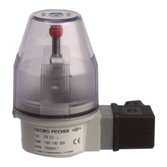
Electrical Position Indicator
Type ER 52, ER 53
Operating Instructions
Elektrischer Rückmelder Typ
ER 52, ER 53
Betriebsanleitung
Indicateur électrique de posi-
tion Typ ER 52, ER 53
Manuel d'utilisation
Indicador de posición eléctrico
Tipo ER 52, ER 53
Manual de instrucciones
198150424 Electrical Position Indicator ER 52, ER 53
6491 / DE EN FR ES / 06 (10.2022)
© Georg Fischer Piping Systems Ltd
CH-8201 Schaffhausen/Switzerland
+41 52 631 30 26/info.ps@georgfischer.com
www.gfps.com
Advertisement
Chapters
Table of Contents

Subscribe to Our Youtube Channel
Related Manuals for +GF+ ER 52


Summary of Contents for +GF+ ER 52
- Page 1 Manuel d'utilisation Indicador de posición eléctrico Tipo ER 52, ER 53 Manual de instrucciones 198150424 Electrical Position Indicator ER 52, ER 53 6491 / DE EN FR ES / 06 (10.2022) © Georg Fischer Piping Systems Ltd CH-8201 Schaffhausen/Switzerland +41 52 631 30 26/info.ps@georgfischer.com...
- Page 2 Content Electrical Position Indicator Type ER 52, ER 53 Elektrischer Rückmelder Typ ER 52, ER 53 Indicateur électrique de position Typ ER 52, ER 53 Indicador de posición eléctrico Tipo ER 52, ER 53...
- Page 3 GF Piping Systems Electrical Position Indicator Type ER 52, ER 53 Operating Instructions...
- Page 4 GF Piping Systems Translation of the original instruction manual Disclaimer The technical data are not binding. It does not constitute expressly warranted characteristics and neither guaranteed properties nor guaranteed durability. It is subject to modification. Our General Terms of Sale apply. Observe instruction manual The instruction manual is part of the product and an important element within the safety concept.
-
Page 5: Table Of Contents
Operating Instructions Electrical Position Indicator Type ER 52, ER 53 Table of Contents Introduction Intended use Scope of delivery Other applicable documents Symbols Abbreviations EC-and UKCA Declaration of conformity Safety Information Meaning of the signal words Observe instruction manual Putting into operation, use and disassembly only by qualified personnel... - Page 6 Electrical Position Indicator Type ER 52, ER 53 Operating Instructions...
-
Page 7: Introduction
Operating Instructions Electrical Position Indicator Type ER 52, ER 53 Introduction Intended use The Electrical Position Indicator is used to indicate the valve position of Diaphragm Valves Type DIASTAR. The Position Indicator can be screwed directly onto the Diaphragm Valve Type DIASTAR. -
Page 8: Abbreviations
Electrical Position Indicator Type ER 52, ER 53 Operating Instructions Abbreviations Abbreviation Designation Nominal diameter Mode of action Double-acting spring resistance Mode of action Spring resistance closed Mode of action Spring resistance closed Pneumatic actuator EC-and UKCA Declaration of conformity The manufacturer GF Piping Systems AG, 8201 Schaffhausen (Switzerland) declares that the products listed below are in comp- liance with the EMC Directive 2014/30/EU and meet such requirements. -
Page 9: Safety Information
Operating Instructions Electrical Position Indicator Type ER 52, ER 53 Safety Information Meaning of the signal words In this instruction manual, warnings are used, which shall warn the user of death, injuries or material damage. Always read and observe these warnings! -
Page 10: General Safety Information
Electrical Position Indicator Type ER 52, ER 53 Operating Instructions General safety information NOTE! These safety instructions do not take into account any contingencies and events that may occur during assembly, operation and service of the devices, nor any location-related safety regulations, compliance with which, also with regard to the installation per- sonnel, is the responsibility of the operator. - Page 11 Operating Instructions Electrical Position Indicator Type ER 52, ER 53 WARNING! Damage due to environmental influences! Solar radiation and temperature fluctuations can cause malfunctions or leaks. ► Protect product from sun and weather conditions when used outdoors. ► Observe permissible ambient temperatures.
-
Page 12: Design And Function
Electrical Position Indicator Type ER 52, ER 53 Operating Instructions Design and function Design Type ER 52 (DN 15-50) Type ER 53 (DN 65-150) Bezeichnung Cover SAN Microswitch «closed» Microswitch «open» Cam PA O-rings NBR Housing PP Brass base Spindle of stainless steel... - Page 13 Operating Instructions Electrical Position Indicator Type ER 52, ER 53 3.2.2 Actuator sizes DIASTAR DN 15–50 DIASTAR size Size (PP-GF) Dimension Size Type DIASTAR Ten DIASTAR TenPlus DIASTAR Sixteen Function FC/DA/FO FC/DA/FO DA/FO DN15 DN20 DN25 DN32 DN40 DN50...
-
Page 14: Technical Data
Electrical Position Indicator Type ER 52, ER 53 Operating Instructions Technical data Type Type of switch Switching capacity ER 52 ER 53 ER 52/53-1 Microswitch AgNi 250 V~/ 6 A 250 V~/ 10 A ER 52/53-2 Microswitch with gold-plated Au 4 –... -
Page 15: Installation
Operating Instructions Electrical Position Indicator Type ER 52, ER 53 Installation DANGER! Risk of injury due to high pressure in the system/device. ► Before working on the system or device, switch off the pressure and vent/drain the lines. Risk of injury from electric shock! ►... - Page 16 Electrical Position Indicator Type ER 52, ER 53 Operating Instructions Unscrew the transparent protective cover 3. Pull upper cam 5 off. Loosen threaded bolt 4. Pull the base 6 with spindle 7 out of the housing. Type ER 52: Complete spindle with respective connecting piece •...
-
Page 17: Diaphragm Valve With Stroke Limiter
Operating Instructions Electrical Position Indicator Type ER 52, ER 53 Diaphragm Valve with Stroke Limiter Put valve in the «open» position using control pressure (function DA only) Remove indicator cap 1. Screw the adapter 9 onto the locknut of the actuator. -
Page 18: Adjustment
Electrical Position Indicator Type ER 52, ER 53 Operating Instructions Unscrew the transparent protective cover 3. Pull upper cam 5 off. Loosen threaded bolt 4. Pull the base 6 with spindle 7 out of the housing. Screw spindle 7 into the spindle nut of the actuator using an Allen key. Observe left-hand thread. -
Page 19: Electrical Connections
Operating Instructions Electrical Position Indicator Type ER 52, ER 53 Electrical Connections Connect unit plug 5.1.1 Normally open function (NO) ► Connect the position indicator with the unit plug, wiring diagrams see chapter 5.2 Connection Function Normally open contact for «OPEN» position Normally open contact for «CLOSED»... -
Page 20: Wiring Diagrams
Electrical Position Indicator Type ER 52, ER 53 Operating Instructions Wiring Diagrams ER 52/53-1&2 Type Code ER 52-1 199 190 305 ER 52-2 199 190 306 ER 53-1 199 190 293 ER 53-2 199 190 297 ER 52-3&4 Type Code... - Page 21 Operating Instructions Electrical Position Indicator Type ER 52, ER 53 ER 52-5 Type Code ER 52-5 199 190 309 ER 53-5 Type Code ER 53-5 199 190 298 Output O 3 mA / o 1 mA to DIN 19234 ER 52/53-6...
-
Page 22: Spare Parts And Accessories
- Profile washer Adapter complete* 199 190 310 Adapter - Size 1 – 2 199 190 387 - Size 3 199 190 388 - Size 4 – 5 199 190 389 *For combination ER 52/ER 53 / stroke limit / manual override... -
Page 23: Disposal
Operating Instructions Electrical Position Indicator Type ER 52, ER 53 Disposal NOTE! Environmental damage due to equipment parts contaminated by media. ► Dispose of the device and packaging in an environmentally friendly manner. ► Comply with applicable disposal regulations and environmental regulations. - Page 24 GF Piping Systems Local support around the world Visit our webpage to get in touch with your local specialist: www.gfps.com/our-locations The information and technical data (altogether “Data”) herein are not binding, unless explicitly confirmed in writing. The Data neither constitutes any expressed, implied or warranted characteristics, nor guaranteed properties or a guaranteed durability.
- Page 25 GF Piping Systems Elektrischer Rückmelder Typ ER 52, ER 53 Betriebsanleitung...
- Page 26 GF Piping Systems Originalbetriebsanleitung Haftungsausschluss Die technischen Daten sind unverbindlich. Sie gelten nicht als zugesicherte Eigenschaften, oder als Beschaffenheits- oder Haltbarkeits- garantien. Änderungen vorbehalten. Es gelten unsere Allgemeinen Verkaufsbedingungen. Betriebsanleitung beachten Die Betriebsanleitung ist Teil des Produkts und ein wichtiger Baustein im Sicherheitskonzept. ►...
- Page 27 Betriebsanleitung Elektrischer Rückmelder Typ ER 52, ER 53 Inhaltsverzeichnis Einleitung Bestimmungsgemässe Verwendung Lieferumfang Mitgeltende Dokumente Symbole Abkürzungen EG-und UKCA Konformitätserklärung Sicherheitshinweise Bedeutung der Signalwörter Betriebsanleitung beachten Inbetriebnahme, Benutzung und Demontage nur durch Fachpersonal Lagerung und Transport Allgemeine Sicherheitshinweise Produktspezifische Sicherheitshinweise...
- Page 28 Elektrischer Rückmelder Typ ER 52, ER 53 Betriebsanleitung...
-
Page 29: Einleitung
Betriebsanleitung Elektrischer Rückmelder Typ ER 52, ER 53 Einleitung Bestimmungsgemässe Verwendung Der elektrische Rückmelder dient zur Signalisierung der Ventilstellung von Membranventilen Typ DIASTAR. Der Rückmelder ist di- rekt auf das Membranventil Typ DIASTAR aufschraubbar. Der elektrische Rückmelder ist für folgende Dimensionen bestimmt: ►... -
Page 30: Abkürzungen
Elektrischer Rückmelder Typ ER 52, ER 53 Betriebsanleitung Abkürzungen Abkürzung Bezeichnung Nenndurchmesser Wirkungsweise Federkraft doppeltwirkend Wirkungsweise Federkraft schliessend Wirkungsweise Federkraft öffnend Pneumatischer Stellantrieb EG-und UKCA Konformitätserklärung Der Hersteller Georg Fischer Rohrleitungssysteme AG, 8201 Schaffhausen (Schweiz) erklärt, dass die nachfolgend genannten Produkte im Sinne der EMV-Richtlinie 2014/30/EU sind, und solchen Anforderungen dieser Richtlinie entsprechen. -
Page 31: Sicherheitshinweise
Betriebsanleitung Elektrischer Rückmelder Typ ER 52, ER 53 Sicherheitshinweise Bedeutung der Signalwörter In dieser Anleitung werden Warnhinweise verwendet, um den Anwender vor Tod, Verletzungen oder vor Sachschäden zu warnen. Diese Warnhinweise müssen immer gelesen und beachtet werden! GEFAHR! Unmittelbar drohende Gefahr! Bei Nichtbeachtung drohen Tod oder schwerste Verletzungen. -
Page 32: Allgemeine Sicherheitshinweise
Elektrischer Rückmelder Typ ER 52, ER 53 Betriebsanleitung Allgemeine Sicherheitshinweise HINWEIS! Diese Sicherheitshinweise berücksichtigen keine Zufälligkeiten und Ereignisse, die bei Montage, Betrieb und Wartung der Geräte auftreten können, sowie keine ortsbezogenen Sicherheitsbestimmungen, für deren Einhaltung, auch in Bezug auf das Montageper- sonal, der Betreiber verantwortlich ist. - Page 33 Betriebsanleitung Elektrischer Rückmelder Typ ER 52, ER 53 WARNUNG! Beschädigung durch Umebungseinflüsse! Sonneneinstrahlung und Temperaturschwankungen können Fehlfunktionen oder Undichtheiten bewirken. ► Produkt bei Einsatz im Aussenbereich vor Sonne und Witterungsverhältnissen schützen. ► Zulässige Umgebungstemperaturen beachten. HINWEIS! Beständigkeiten der Werkstoffe beachten! Die Werkstoffe des Produkts sind teilweise nicht säurebeständig.
-
Page 34: Aufbau Und Funktion
Elektrischer Rückmelder Typ ER 52, ER 53 Betriebsanleitung Aufbau und Funktion Aufbau Typ ER 52 (DN 15-50) Typ ER 53 (DN 65-150) Bezeichnung Haube SAN Mikroschalter «Zu» Mikroschalter «Auf» Nocken PA O-Ringe NBR Gehäuse PP Sockel Messing Spindel ST Rostfrei Anschlussstück ST Rostfrei... - Page 35 Betriebsanleitung Elektrischer Rückmelder Typ ER 52, ER 53 3.2.2 Antriebsgrössen DIASTAR DN 15–50 DIASTAR Grösse Grösse (PP-GF) Dimension Grösse DIASTAR Ten DIASTAR TenPlus DIASTAR Sixteen Funktion FC/DA/FO FC/DA/FO DA/FO DN15 DN20 DN25 DN32 DN40 DN50...
-
Page 36: Technische Daten
Elektrischer Rückmelder Typ ER 52, ER 53 Betriebsanleitung Technische Daten Schaltertyp Schalterleistung ER 52 ER 53 ER 52/53-1 Mikroschalter AgNi 250 V~/ 6 A 250 V~/ 10 A ER 52/53-2 Mikroschalter mit Goldkontakt Au 4 – 30 V= / 1-100 mA 4 –... -
Page 37: Montage
Betriebsanleitung Elektrischer Rückmelder Typ ER 52, ER 53 Montage GEFAHR! Verletzungsgefahr durch hohen Druck in Anlage/Gerät. ► Vor Arbeiten an Anlage oder Gerät, den Druck abschalten und Leitungen entlüften/entleeren. Verletzungsgefahr durch Stromschlag! ► Vor Eingriffen in das Gerät oder die Anlage, Spannung abschalten und vor Wiedereinschalten sichern! ►... - Page 38 Elektrischer Rückmelder Typ ER 52, ER 53 Betriebsanleitung Transparente Schutzhaube 3 abschrauben. Obere Nocke 5 abziehen. Gewindestift 4 lösen. Sockel 6 mit Spindel 7 aus Gehäuse ziehen. Bei Typ ER 52: Komplette Spindel mit entsprechendem Anschlussstück ergänzen. • Sockel um 180° drehen (Einbau siehe Kapitel «Funktion»).
-
Page 39: Membranventil Mit Hubbegrenzung
Betriebsanleitung Elektrischer Rückmelder Typ ER 52, ER 53 Membranventil mit Hubbegrenzung Ventil mit Steuerdruck in Stellung (Nur Funktion DA. Anzeigekappe 1 demontieren. Adapter 9 auf Sicherungsmutter am Stellantrieb schrauben. Bei ER 53: Anzeigestift demontieren. Dabei Linksgewinde des Anzeigestifts beachten. •... -
Page 40: Justierung
Elektrischer Rückmelder Typ ER 52, ER 53 Betriebsanleitung Transparente Schutzhaube 3 abschrauben. Obere Nocke 5 abziehen. Gewindestift 4 lösen. Sockel 6 mit Spindel 7 aus Gehäuse ziehen. Spindel 7 mit Innensechskantschlüssel in Spindelmutter des Stellantriebes schrauben. Dabei Linksgewinde beachten. Sockel 6 mit Schraubenschlüssel in Stellantrieb schrauben. -
Page 41: Elektische Anschlüsse
Betriebsanleitung Elektrischer Rückmelder Typ ER 52, ER 53 Elektische Anschlüsse Gerätestecker belegen 5.1.1 Schliessfunktion (NO) ► Rückmelders mit dem Gerätestecker anschliessen, Anschlussschaltbilder siehe Kapitel 5.2. Anschluss Funktion Schliesser für «AUF»-Position Schliesser für «ZU»-Position Speisung für beide Mikroschalter 5.1.2 Öffnerfunktion (NC) ►... -
Page 42: Anschlusschaltbilder
Elektrischer Rückmelder Typ ER 52, ER 53 Betriebsanleitung Anschlusschaltbilder ER 52/53-1&2 Code ER 52-1 199 190 305 ER 52-2 199 190 306 ER 53-1 199 190 293 ER 53-2 199 190 297 ER 52-3&4 Code ER 52-3 199 190 307... - Page 43 Betriebsanleitung Elektrischer Rückmelder Typ ER 52, ER 53 ER 52-5 Code ER 52-5 199 190 309 ER 53-5 Code ER 53-5 199 190 298 Ausgang O 3 mA / o 1 mA nach DIN 19234 ER 52/53-6 Code ER 52-6...
-
Page 44: Ersatzteilliste Und Zubehör
198 000 216 - Profildichtung Adapter komplett* 199 190 310 Adapter - Grösse 1 – 2 199 190 387 - Grösse 3 199 190 388 - Grösse 4 – 5 199 190 389 *Für Kombination ER 52/ER 53 / Hubgrenzung / Handnotbetätigung... -
Page 45: Entsorgung
Betriebsanleitung Elektrischer Rückmelder Typ ER 52, ER 53 Entsorgung HINWEIS! Umweltschäden durch von Medien kontaminierte Geräteteile. ► Gerät und Verpackung umweltgerecht entsorgen. ► Geltende Entsorgungsvorschriften und Umweltbestimmungen einhalten. WARNUNG! Kontaminierte Bauteile! Teile des Produkts können mit gesundheits- und umweltschädlichen Medien kontaminiert sein, so dass eine einfache Reinigung nicht ausreichend ist. - Page 46 GF Piping Systems Lokale Unterstützung – weltweit Besuchen Sie unsere Website und kontaktieren Sie Ihren lokalen Spezialisten: www.gfps.com/our-locations Die hierin enthaltenen Informationen und technischen Daten (insgesamt „Daten”) sind nicht verbindlich, sofern sie nicht ausdrücklich schriftlich bestätigt werden. Die Daten begründen weder ausdrückliche, stillschweigende oder zugesicherte Merkmale noch garantierte Eigenschaften oder eine garantierte Haltbarkeit.
- Page 47 GF Piping Systems Indicateur électrique de po- sition Typ ER 52, ER 53 Manuel d'utilisation...
- Page 48 GF Piping Systems Traduction du manuel d'utilisation original Exclusion de responsabilité Les données techniques ne sont pas contractuelles. Elles ne sont pas des garanties et ne constituent pas non plus un gage de propriété intrinsèque ou de durabilité. Sous réserve de modifications. Nos conditions générales de vente s’appliquent. Se reporter au manuel d'utilisation Le manuel d'utilisation fait partie intégrante du produit et constitue un élément essentiel du concept de sécurité.
- Page 49 Manuel d'utilisation Indicateur électrique de position Typ ER 52, ER 53 Sommaire Introduction Utilisation selon les dispositions Contenu de la livraison Documents applicables Symboles Abréviations Déclaration de conformité CE et UKCA Consignes de sécurité Signification des termes d'avertissement Se reporter au manuel d'utilisation Mise en service, utilisation et démontage réservés à...
- Page 50 Indicateur électrique de position Typ ER 52, ER 53 Manuel d'utilisation...
-
Page 51: Introduction
Manuel d'utilisation Indicateur électrique de position Typ ER 52, ER 53 Introduction Utilisation selon les dispositions L’indicateur électrique sert à la signalisation des positions d’ouverture et de fermeture du robinet à membrane de type DIASTAR. L’indicateur électrique de position se fixe directement sur le robinet à membrane de type DIASTAR. -
Page 52: Abréviations
Indicateur électrique de position Typ ER 52, ER 53 Manuel d'utilisation Abréviations Abréviation Désignation Diamètre nominal Mode de fonctionnement à double effet de la force du ressort Mode de fonctionnement fermé de la force du ressort Mode de fonctionnement ouvert de la force du ressort Servomécanisme pneumatique... -
Page 53: Consignes De Sécurité
Manuel d'utilisation Indicateur électrique de position Typ ER 52, ER 53 Consignes de sécurité Signification des termes d'avertissement Des avertissements sont utilisés dans ce manuel d'utilisation afin de signaler à l'utilisateur un danger de mort, un risque de bles- sures ou des dégâts matériels. Toujours lire et respecter ces avertissements ! DANGER ! -
Page 54: Consignes De Sécurité Générales
Indicateur électrique de position Typ ER 52, ER 53 Manuel d'utilisation Consignes de sécurité générales REMARQUE ! Ces consignes de sécurité ne prennent pas en compte les aléas et les évènements qui peuvent survenir lors du montage, de l'exploi- tation et de l'entretien des appareils, ni aucune disposition de sécurité spécifique au site, dont l'exploitant est responsable du res- pect, même par rapport au personnel de montage. - Page 55 Manuel d'utilisation Indicateur électrique de position Typ ER 52, ER 53 AVERTISSEMENT ! Dommages causés par les vibrations ! Le rayonnement du soleil et des variations de température peuvent occasionner des dysfonctionnements ou des défauts d'étanchéi- té. ► Protéger le produit du soleil et des conditions météorologiques en cas d'utilisation en extérieur.
-
Page 56: Structure Et Caractéristique
Indicateur électrique de position Typ ER 52, ER 53 Manuel d'utilisation Structure et caractéristique Structure Type ER 52 (DN 15-50) Type ER 53 (DN 65-150) Bezeichnung Capot transparent en SAN Microcontacteur «FERME» Microcontacteur «OUVERT» Came de commande en PA Joints toriques en NBR Boîtier en PP... - Page 57 Manuel d'utilisation Indicateur électrique de position Typ ER 52, ER 53 3.2.2 Grandeurs du servomécanisme DIASTAR Grandeur grandeur (PP-GF) Dimension Grandeur Type DIASTAR Ten DIASTAR TenPlus DIASTAR Sixteen Fonction FC/DA/FO FC/DA/FO DA/FO DN15 DN20 DN25 DN32 DN40 DN50...
-
Page 58: Caractéristiques Techniques
Indicateur électrique de position Typ ER 52, ER 53 Manuel d'utilisation Caractéristiques techniques Type Type d’interrupteur Pouvoir de coupure ER 52 ER 53 ER 52/53-1 Microcontacteur AgNi 250 V~/ 6 A 250 V~/ 10 A ER 52/53-2 Microcontacteur à contacts or Au 4 –... -
Page 59: Installation
Manuel d'utilisation Indicateur électrique de position Typ ER 52, ER 53 Installation DANGER ! Risque de blessures dû à la pression élevée dans l‘installation / l‘appareil. ► Avant d'effectuer des travaux sur l'installation ou l'appareil, couper la pression et purger l'air des / vider les conduites. - Page 60 Indicateur électrique de position Typ ER 52, ER 53 Manuel d'utilisation Dévisser le capot de protection 3. Retirer la came supérieure 5. Desserrer la vis sans tête 4. Retirer le socle 6 avec la broche 7 du boîtier. Pour le type ER 52 : Compléter la broche complète avec le raccord correspondant.
-
Page 61: Robinet À Membrane Avec Limiteur De Course
Manuel d'utilisation Indicateur électrique de position Typ ER 52, ER 53 Robinet à membrane avec limiteur de course Mettre le robinet dans la position «OUVERT» au moyen de la pression de commande (DA). Démonter le capot de l’indicateur 1. Visser l’adaptateur 9 sur l’écrou de sécurité sur le servomécanisme. -
Page 62: Ajustage
Indicateur électrique de position Typ ER 52, ER 53 Manuel d'utilisation Dévisser le capot de protection transparent 3. Retirer la came supérieure 5. Desserrer la vis sans tête 4. Retirer le socle 6 avec la broche 7 du boîtier. Visser la broche 7 dans l‘écrou de la broche du servomécanisme à l‘aide d‘une clé à six pans creux. Tenir compte du filetage à... -
Page 63: Raccordements Électriques
Manuel d'utilisation Indicateur électrique de position Typ ER 52, ER 53 Raccordements électriques Utiliser raccordement 5.1.1 Fonction de la fermeture ► Le raccordement de l’indicateur électrique ER 53 s’effectue normalement par son connecteur. Broche du Fonction connecteur Contact de travail pour position «OUVERT»... -
Page 64: Schémas De Raccordement
Indicateur électrique de position Typ ER 52, ER 53 Manuel d'utilisation Schémas de raccordement ER 52/53-1&2 Type Code ER 52-1 199 190 305 ER 52-2 199 190 306 ER 53-1 199 190 293 ER 53-2 199 190 297 ER 52-3&4... - Page 65 Manuel d'utilisation Indicateur électrique de position Typ ER 52, ER 53 ER 52-5 Type Code ER 52-5 199 190 309 ER 53-5 Type Code ER 53-5 199 190 298 Sortie O 3 mA / o 1 mA selon DIN ¢9234...
-
Page 66: Pièces De Rechange Et Accessoires
199 190 310 Adaptateur - Grandeur 1 – 2 199 190 387 - Grandeur 3 199 190 388 - Grandeur 4 – 5 199 190 389 *Pour combinaison ER 52/ER 53 / Limiteur de course / commande manuelle de secours... -
Page 67: Elimination
Manuel d'utilisation Indicateur électrique de position Typ ER 52, ER 53 Elimination REMARQUE ! Dégâts environnementaux causés par les pièces de l‘appareil contaminées par des fluides. ► Éliminer l›appareil et son emballage dans le respect des normes environnementales. ► Respecter les prescriptions applicables en matière d›élimination, ainsi que les dispositions en matière d‘environnement. - Page 68 GF Piping Systems Assistance locale dans le monde entier Rendez-vous sur notre site internet pour contacter votre expert local : www.gfps.com/our-locations Les informations et les données techniques (ci-après « Données ») contenues ici ne sont pas contractuelles, sauf mention explicite par écrit. Les données ne constituent pas une garantie expresse ou implicite des caractéristiques et ne garantissent pas des propriétés spécifiques ou une durabilité.
- Page 69 GF Piping Systems Indicador de posición eléc- trico Tipo ER 52, ER 53 Manual de instrucciones...
- Page 70 GF Piping Systems Traducción de las instrucciones de uso originales Exoneración de responsabilidad Los datos técnicos no son vinculantes. No representan ninguna garantía de las características, condiciones o durabilidad del dispositivo. Sujeto a modificaciones. Son válidas nuestras Condiciones Generales de Venta. Obsérvese el manual de instrucciones El manual de instrucciones forma parte del producto y es un elemento importante del concepto de seguridad.
- Page 71 Manual de instrucciones Indicador de posición eléctrico Tipo ER 52, ER 53 Índice Introducción Uso conforme a lo dispuesto Contenido Documentación complementaria Símbolos Abreviaturas Declaración de conformidad CE e UKCA Advertencias de seguridad Significado de las palabras de señalización Obsérvese el manual de instrucciones Puesta en funcionamiento, uso y desmontaje solo por parte del personal técnico...
- Page 72 Indicador de posición eléctrico Tipo ER 52, ER 53 Manual de instrucciones Eliminación...
-
Page 73: Introducción
Manual de instrucciones Indicador de posición eléctrico Tipo ER 52, ER 53 Introducción Uso conforme a lo dispuesto El indicador de posición eléctrico sirve para señalizar la posición de válvula de las válvulas de diafragma del tipo DIASTAR. El indi- cador de posición se puede enroscar directamente en la válvula de diafragma del tipo DIASTAR. -
Page 74: Abreviaturas
Indicador de posición eléctrico Tipo ER 52, ER 53 Manual de instrucciones Abreviaturas Abreviatura Denominación Diámetro nominal Modo de acción de la resistencia de resorte de efecto doble Modo de acción del cierre de la resistencia de resorte Modo de acción de la apertura de la resistencia de resorte Actuador neumático... -
Page 75: Advertencias De Seguridad
Manual de instrucciones Indicador de posición eléctrico Tipo ER 52, ER 53 Advertencias de seguridad Significado de las palabras de señalización En este manual se utilizan indicaciones de advertencia para advertir al usuario de peligros mortales, lesiones, o daños materiales. -
Page 76: Advertencias De Seguridad Generales
Indicador de posición eléctrico Tipo ER 52, ER 53 Manual de instrucciones Advertencias de seguridad generales NOTA Las presentes advertencias de seguridad no tienen en cuenta las coincidencias ni los eventos que puedan producirse durante el ensamblaje, el funcionamiento y el servicio de los aparatos. Tampoco tienen en cuenta las normas de seguridad específicas de la ubicación que la empresa explotadora debe cumplir, también en lo que respecta al personal de montaje. - Page 77 Manual de instrucciones Indicador de posición eléctrico Tipo ER 52, ER 53 ADVERTENCIA ¡Daños debidos a las influencias ambientales! La radiación solar y las fluctuaciones de temperatura pueden provocar averías o fugas. ► Proteger el producto del sol y las inclemencias del tiempo en caso de uso en el exterior.
-
Page 78: Componentes Y Funcionamiento
Indicador de posición eléctrico Tipo ER 52, ER 53 Manual de instrucciones Componentes y funcionamiento Componentes Tipo ER 52 (DN 15-50) Tipo ER 53 (DN 65-150) Bezeichnung Cubierta SAN Microinterruptor «cerrado» Microinterruptor «abierto» Levas PA Anillos tóricos NBR Carcasa PP Zócalo latón... - Page 79 Manual de instrucciones Indicador de posición eléctrico Tipo ER 52, ER 53 3.2.2 Tamaños de actuador DIASTAR DN 15–50 DIASTAR tamaño Tamaño (PP-GF) Dimensión Tamaño Tipo DIASTAR Ten DIASTAR TenPlus DIASTAR Sixteen Función FC/DA/FO FC/DA/FO DA/FO DN15 DN20 DN25 DN32...
-
Page 80: Datos Técnicos
Indicador de posición eléctrico Tipo ER 52, ER 53 Manual de instrucciones Datos técnicos Tipo Tipo de interruptor Potencia de conmutación ER 52 ER 53 ER 52/53-1 Microinterruptor AgNi 250 V~/ 6 A 250 V~/ 10 A ER 52/53-2 Microinterruptor con contacto de oro Au 4 –... -
Page 81: Instalación
Manual de instrucciones Indicador de posición eléctrico Tipo ER 52, ER 53 Instalación PELIGRO Riesgo de lesiones por alta presión en la instalación/el aparato. ► Antes de trabajar en la instalación o el aparato, apagar la presión y vaciar/drenar los conductos. - Page 82 Indicador de posición eléctrico Tipo ER 52, ER 53 Manual de instrucciones Desenroscar la cubierta transparente 3. Retirar la leva superior 5. Aflojar el pasador roscado 4. Retirar el zócalo 6 con el husillo 7 de la carcasa. En el tipo ER 52: Completar el husillo completo con la pieza de empalme correspondiente.
-
Page 83: Válvula De Diafragma Con Limitación De Carrera
Manual de instrucciones Indicador de posición eléctrico Tipo ER 52, ER 53 Válvula de diafragma con limitación de carrera Poner la válvula con presión de control en posición «abierta» (Función DA) Desmontar el tapón indicador 1. Enroscar el adaptador 9 a la contratuerca del actuador. -
Page 84: Ajuste
Indicador de posición eléctrico Tipo ER 52, ER 53 Manual de instrucciones Desenroscar la cubierta transparente 3. Retirar la leva superior 5. Aflojar el pasador roscado 4. Retirar el zócalo 6 con el husillo 7 de la carcasa. Enrosca el husillo 7 en la tuerca del actuador con una llave tornillos. Observa la rosca de la izquierda. -
Page 85: Conexiones Eléctricas
Manual de instrucciones Indicador de posición eléctrico Tipo ER 52, ER 53 Conexiones eléctricas Ocupación de conectores del aparato 5.1.1 Función de cierre ► Conectar el indicador de posición con el conector del aparato, véanse los esquemas de conexiones en el capítulo. -
Page 86: Esquemas De Conexiones
Indicador de posición eléctrico Tipo ER 52, ER 53 Manual de instrucciones Esquemas de conexiones ER 52/53-1&2 Tipo Code ER 52-1 199 190 305 ER 52-2 199 190 306 ER 53-1 199 190 293 ER 53-2 199 190 297 ER 52-3&4... - Page 87 Manual de instrucciones Indicador de posición eléctrico Tipo ER 52, ER 53 ER 52-5 Tipo Code ER 52-5 199 190 309 ER 53-5 Tipo Code ER 53-5 199 190 298 Salida O 3 mA / o 1 mA conforme a DIN 19234...
-
Page 88: Lista De Repuestos Y Accesorios
199 190 310 Adaptador - Tamaño 1 – 2 199 190 387 - Tamaño 3 199 190 388 - Tamaño 4 – 5 199 190 389 *Para la combinación ER 52/ER 53 / limitación de carrera / accionamiento de emergencia manual... - Page 89 Manual de instrucciones Indicador de posición eléctrico Tipo ER 52, ER 53 Eliminación NOTA Daños medioambientales debido la contaminación de partes del aparato. ► Eliminar el aparato y el embalaje de forma respetuosa con el medioambiente. ► Respetar las regulaciones de eliminación y ambientales aplicables.
- Page 90 GF Piping Systems Asistencia local en todo el mundo Visite nuestra web para ponerse en contacto con su especialista local: www.gfps.com/our-locations Esta información y características técnicas (en adelante, “datos”) no son vinculantes a no ser que se confirme expresamente por escrito. Los datos no constituyen características explícitas, implícitas o garantizadas, propiedades garantizadas o una garantía de durabilidad.
Need help?
Do you have a question about the ER 52 and is the answer not in the manual?
Questions and answers