
Subscribe to Our Youtube Channel
Related Manuals for Tsurumi Pump FHP Series


Summary of Contents for Tsurumi Pump FHP Series
- Page 3 Be sure to thoroughly read and understand the SAFETY PRECAUTIONS given in this section before using the equipment in order to operate the equipment correctly. The precautionary measures described in this section are intended to prevent danger or damage to you or to others.
- Page 4 CAUTION Be sure to provide a ground wire Prevent a metallic object or dust securely. Do not connect the from sticking to the power plug. ground wire to a gas pipe, water Adhesion of foreign object to the plug could cause electrical pipe, lightening rod, or telephone ground wire.
- Page 5 CAUTION Do not use the product in hot or When the product will not be used warm liquid over 40°C, as doing so for an extended period, be sure to will damage the product, which turn off the power supply (earth may lead to electrical leakage or leakage circuit breaker, etc.).
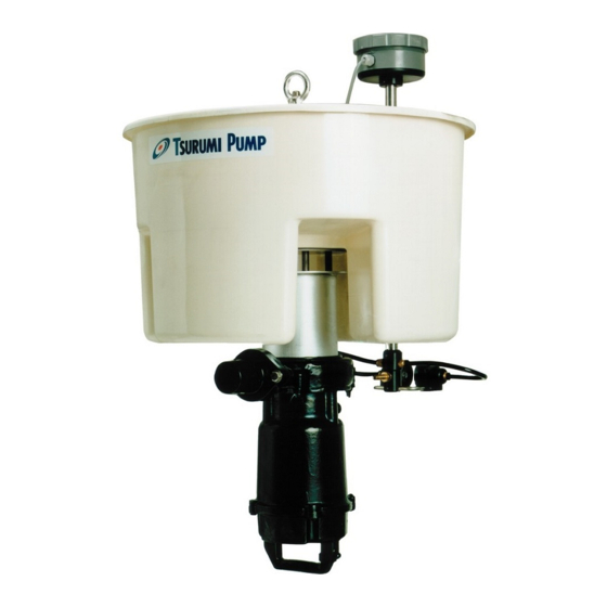
- Page 6 Eyenut Float Anti-sludge Sensor Signal Cable Amplifier Unit Water Inlet Amplifier Unit Box Check Ball Screwed Flange Fiber Glass Hose Coupling Support Piping Pump Casing Oil Seal Oil Casing Oil Plug Impeller Shaft Sleeve Lubricant Sealing Tube Mechanical Seal Handle Cabtyre Cable Fiber Unit Sensor Cleaning...
- Page 7 Unit Composition Anti-sludge sensor Hose coupling Chain w/ Shackle (SUS304, 3m) Ground name plate Operation manual Note: CAUTION Fluid Property Treated water, 0∼40ºC Channel Impeller Impeller Shaft Seal Double Mechanical Seal Pump Bearing Shielded Ball Bearing Specifications Dry type submersible induction motor, 2-pole Insulation Class E and F Motor...
- Page 8 CAUTION Note: CAUTION Applicable Pump Cirtical Use Pressure Models with output of 0.75kW or under 0.2MPa (2kgf/cm ) — discharge pressure during use Models with output of 1.5kW 0.3MPa (3kgf/cm ) — discharge pressure during use Note: MΩ U V W G U-Red(Brown) G-Green(Green/Yellow) V-White(Grey)
- Page 9 WARNING CAUTION CAUTION Chain Hose CAUTION Pump unit Cabtyre cable Hook Guide support M10 bolts/nuts Lowest water level (Option) (L.W.L) of settled water 1000∼1200mm Stopper (Vertically movable) 25a-sus304tp-sch10s (Option) Guide pipe stay M10 bolts/nuts (Option)
- Page 10 CAUTION Anti-sludge sensor cable Amplifier unit box Guide support Hook Float Sensor cleaning water hose Anti-sludge sensor Water inlet Check ball Sensor cleaning nozzle Discharge hose Submersible pump Note: Guide pipe Stopper Guide pipe stay Note: CAUTION CAUTION Shackle Eyenut...
- Page 11 WARNING WARNING CAUTION WARNING CAUTION Single-Phase Circuit Breaker CAUTION Ground Three-Phase Ground Note: U-Red(Brown) G-Green (Green/Yellow) V-White(Grey) W-Black(Black) Condenser Starting Direct-on-line Starting Anti-Sludge Sensor Power Supply: Single-Phase Anplifier Unit Sensor Controller Operating Capacitor Sensing Dial Centrifugal Beam Fiber Main Coil Switch Aux.
- Page 12 Shield Controller Sensor Discharge mode cable Signal S3D2-CK 7 8 9 10 11 12 1 2 3 4 5 6 AR: Aux relay 3SEC 10SEC T: Timer Submersible decanting pump start signal se this signal to actuate the pump's magnetic switch. Note:...
- Page 13 CAUTION Note: Note: WARNING CAUTION WARNING COUNTERMEASURE COUNTERMEASURE COUNTERMEASURE CAUTION...
- Page 14 WARNING Note: Sensor Pump Level Sensor Water Level Level sensor Beam penetrating Starts Beam not penetrating (senses sludge layer) Stops Beam penetrating After 10 minutes Restarts Beam penetrating Stops ※The flow rate per discharge is determined by the control range of the level sensor. Water Pressure Physical Outlet...
- Page 15 Note: Note: WARNING Note:...
- Page 16 Interval Inspection Item Measure operating current To be below the rated current. Daily Measure power voltage Power supply voltage tolerance (within ±5% of the rated voltage) Measure insulation resistance Reference insulation resistance = 1MΩ or greater Monthly Note: If the insulation resistance has become notably lower than the precious inspection, an inspection of the motor will be necessary.
- Page 17 Part Recommended Frequency Mechanical Seal When oil becomes milky. Oil (Turbine Oil VG 32 (Additive-free) ) Every 12 mouths or after 3,000 hours of use, whichever comes first. Packing, O-Ring Each time unit is disassembled or inspected Oil Seal When lip is worn, and each time unit is disassembled or inspected Shaft Sleeve If worn WARNING...
- Page 18 Anti-Sludge Sensor Eyenut Suction Pipe Adapter Hex.Nut Spring Hex.Bolt Stud Bolt Washer Check Ball Sleeve Oil Seal Hex.Nut O-ring Pump Casing Packing Screw Flange Hose Coupling Packing Impeller Nut Plane Washer Spring Washer Hex.Bolt Impeller Impeller Adusting Washer Float Shaft Sleeve Oil Seal Stud Bolt Packing...
- Page 19 Sensitivity Indicator Low Sensitivity High Sensitivity SENS. Sensing Dial Output Beam Penetrating Sensitivity Step Adjustment Method Indicator Or Not Penetrating Indicator Light Adjust the sensing dial to "Min". SENS. This step is performed while the beam is not Beam not penetrating.
- Page 20 WARNING Problem Possible cause Countermeasure (1)No power supply (power outage, (1)Contact the power company or an electrical etc.) repair ship. (2)Disconnection or inadequate (2)Check if the cabtyre cable or wiring is connection of cabtyre cable. disconnected. Pump fails to start (3)Foreign object lodging on impeller (3)Check and remove any debris.
Need help?
Do you have a question about the FHP Series and is the answer not in the manual?
Questions and answers