Table of Contents
Advertisement
Quick Links
KTV/NK Series
Submersible General Dewatering Pump
INTRODUCTION
Thank you for selecting the Tsurumi KTV/NK Series submersible general dewatering pump.
This operation manual explains the product operations and gives important precautions regarding its safe
use. In order to use the product to maximum benefit, be sure to read the instructions thoroughly and follow
them carefully.
To avoid accident, do not use the pump in any way other than as described in this operation manual. Note
that the manufacturer cannot be responsible for accidents arising because the product was not used as
prescribed. After reading this operation manual, keep it nearby as a reference in case questions arise during
use.
When lending this product to another party, always be sure to include this operation manual as well.
If this operation manual should become lost or damaged, ask your nearest dealer or Tsurumi representative
for another copy.
Every effort has been made to ensure the completeness and accuracy of this document. Please contact your
nearest dealer or Tsurumi representative if you notice any possible error or omission.
The contents of this document may not be copied in whole or in part without the express permission of
Tsurumi Manufacturing Co., Ltd.
TSURUMI MANUFACTURING CO., LTD.
OPERATION MANUAL
1. BE SURE TO READ FOR YOUR SAFETY ..................... 1
2. NAME OF PARTS .......................................................... 4
3. PRIOR TO OPERATION ............................................... 5
4. INSTALLATION ............................................................. 6
5. ELECTRICAL WIRING .................................................... 8
6. OPERATION .................................................................... 9
7. MAINTENANCE AND INSPECTION ............................... 12
8. DISASSEMBLY AND REASSEMBLY ............................. 14
9. TROUBLESHOOTING .................................................. 17
CONTENTS
17236124/B-10005-6
Advertisement
Table of Contents

Subscribe to Our Youtube Channel
Related Manuals for Tsurumi Pump KTV series


Summary of Contents for Tsurumi Pump KTV series
-
Page 1: Table Of Contents
17236124/B-10005-6 KTV/NK Series Submersible General Dewatering Pump OPERATION MANUAL INTRODUCTION Thank you for selecting the Tsurumi KTV/NK Series submersible general dewatering pump. This operation manual explains the product operations and gives important precautions regarding its safe use. In order to use the product to maximum benefit, be sure to read the instructions thoroughly and follow them carefully. -
Page 2: Be Sure To Read For Your Safety
1 BE SURE TO READ FOR YOUR SAFETY Be sure to thoroughly read and understand the SAFETY PRECAUTIONS given in this section before using the equipment in order to operate the equipment correctly. The precautionary measures described in this section are intended to prevent danger or damage to you or to others. - Page 3 CAUTION Be sure to provide a ground wire Attach a hose securely to the hose coupling. Imperfect connection of securely. Do not connect the hose could cause water leakage ground wire to a gas pipe, water which may result in the damage pipe, lightening rod, or telephone ground wire.
- Page 4 CAUTION Do not use the product for hot or When the product will not be used warm liquid over 40℃, as doing so for an extended period, be sure to will damage the product, which turn off the power supply (earth may lead to electrical leakage or leakage circuit breaker, etc.).
-
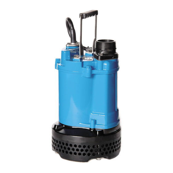
Page 5: Name Of Parts
2 NAME OF PARTS Example ; KTV Series Hose Coupling Cabtyre Cable Handle Oil Lifter Mechanical Seal Lubricant Oil Plug Protective Packing V-Ring Shaft Sleeve Rear Liner Oil Casing Impeller Pump Casing Strainer Stand Note: The above diagram is typical of the KTV2-22, but some models may vary slightly in appearance or internal structure. -
Page 6: Prior To Operation
Pump Shaft Seal Double Mechanical Seal Bearing Shielded Ball Bearing Specification Dry Submersible Induction Motor 2-Pole Insulation Class E (KTV Series), Class B (NK Series) Motor Protection System (Built-in) Circle Thermal Protector Lubricant Turbine oil VG32 (non-additive) Connection Hose Coupling Standard specifications (50/60Hz) -
Page 7: Installation
4 INSTALLATION CAUTION • Do not use this pump in liquids other than water, such as oil, salt water, or organic solvents. • Use with a power supply voltage variation within ± 10% of the rated voltage. • Do not use in water temperatures outside the range of 0 ~ 40°C, which can lead to failure, electrical leakage or shock. - Page 8 (2) Avoid dropping the pump or other strong impact. Lift the pump by holding it firmly with the hands or by attaching a rope or Rope chain to the handle. Note: On Cabtyre cable handling, see below Electrical Wiring. (3) Install the pump in a location with sufficient Backflow Outflow water level, where water collects readily.
-
Page 9: Electrical Wiring
5 ELECTRICAL WIRING Performing electrical wiring WARNING • Eelectrical wiring should be performed by a qualified person in accord with all applicable local regulations. Failure to observe this precaution not only risks breaking the law but is extremely dangerous. • Incorrect wiring can lead to electrical leakage, electrical shock or fire. •... -
Page 10: Operation
Electrical circuit diagrams Direct on line Ground Coil Circle Thermal Protector NK2-15 Capacitor-Start models, Single-phase motor NK2-15 Capacitor-Start models, Single-phase motor (110V-50/60Hz) (220V-50/60Hz) Terminal Block Terminal Block L2T2 P2 P1 T4T5 T1 T3 P1 T4T5 Centrifugal Swich Centrifugal Swich Main Coil1 Main Coil1 Main Coil2 Main Coil2... -
Page 11: Test Operation
(3) The setting on the circuit breaker or other overload protector should be made in accord with the rated currency of the pump. Note: See the model name plate on the pump for its rated current. (4) When powering the pump with a generator, do not share the generator with other equipment. - Page 12 Operation WARNING • The pump may become very hot during operation. Be careful not to contact the pump accidentally to avoid being burned. • To avoid serious injury, do not insert a finger or any other object in the pump inlet holes. •...
-
Page 13: Maintenance And Inspection
7 MAINTENANCE AND INSPECTION Regular maintenance and inspections are a necessity for continued efficient functioning of the pump. If any abnormal conditions are noticed, refer to the section "9.Troubleshooting" and take corrective measures immediately. It is recommended that a spare pump be kept ready in case of any problems. Prior to inspection WARNING Detach the cabtyre cable from the receptacle or terminals, after making... -
Page 14: Replacement Parts
Oil inspection and Oil change Oil Inlet Packing Inspecting oil Oil Plug Remove the oil plug (hex. bolt) and tilt the Spanner pump to drain a small amount of oil. If the oil is milky white or has water mixed in with it, the mechanical seal may be faulty. -
Page 15: Disassembly And Reassembly
8 DISASSEMBLY AND REASSEMBLY WARNING • Before disassembling the pump, first detach the Cabtyre Cable from the receptacle, after making certain the power supply (circuit breaker, etc.) is turned off. To avoid electrical shock, do not work with wet hands. Never check the operation of any parts (impeller rotation, etc.) by turning on the power while the unit is partially assembled. - Page 16 Exploded View ; KTV2-22 Plain Washer Hex. Nut Impeller Nut Pump Casing Packing Oil Plug Fixing Plate Rear Liner Protective Plate Round Head Screw Strainer Stand V-Ring Shaft Sleeve Plain Washer Impeller Hex.Bolt Note: The above exploded view is for model KTV2-22. Other models may differ slightly in shape and construction.
- Page 17 Disassembly (NK2-22) Note: Remove the oil prior to disassembly. (1) Removing the Strainer Stand, Fixing Plate and Pump Casing Remove the Strainer Stand Hex. Bolts and Plain Washers, then remove the Strainer Stand, Fixing Plate and Pump Casing from the pump. (2) Removing the Impeller With a socket wrench or other tool, loosen the Impeller Nut and Hex.
-
Page 18: Troubleshooting
9 TROUBLESHOOTING WARNING Always turn off the power before inspecting the pump. Failure to observe this precaution can result in serious accident. Before ordering repairs, carefully read through this instruction manual, than repeat the inspection. If the probrem remains, contact your nearest dealer or Tsurumi representative. Problem Possible causes Countermeasure...
Need help?
Do you have a question about the KTV series and is the answer not in the manual?
Questions and answers