Tsurumi Pump PU Series Operation Manual
Submersible vortex sewage pump submersible vortex wastewater drainage pump submersible centrifugal effluent drainage pump submersible titanium pump
Hide thumbs
Also See for PU Series:
- Operation manual (23 pages) ,
- Starting and operating instruction (128 pages)
Table of Contents
Advertisement
PU
PN
PSF
TM
INTRODUCTION
Thank you for selecting the Tsurumi PU submersible vortex sewage pump, PN submers-
ible vortex wastewater drainage pump, PSF submersible centrifugal effluent drainage
pump, or TM submersible titanium pump for your application.
This equipment should not be used for applications other than those listed in this manual.
Failure to observe this precaution may lead to a malfunction or an accident. In the event of
a malfunction or an accident, the manufacturer will not assume any liability. After reading
this Operation Manual, keep it in a location that is easily accessible, so that it can be re-
ferred to whenever information is needed while operating the equipment.
TSURUMI MANUFACTURING CO., LTD.
Submersible Vortex Sewage Pump
Submersible Vortex Wastewater Drainage Pump
Submersible Centrifugal Effluent Drainage Pump
Submersible Titanium Pump
OPERATION MANUAL
1.BE SURE TO READ FOR YOUR SAFETY ...................... 1
2.PART NAMES .................................................................. 4
3. PRIOR TO USE ............................................................. 5
4. INSTALLATION ............................................................. 6
5. ELECTRICAL WIRING .................................................... 9
6. OPERATION .................................................................... 12
7. MAINTENANCE AND INSPECTION ............................... 15
8. DISASSEMBLY AND REASSEMBLY PROCEDURE ...... 17
9.TROUBLESHOOTING ................................................... 22
17237127/B-10015-7
CONTENTS
Advertisement
Table of Contents

Related Manuals for Tsurumi Pump PU Series


Summary of Contents for Tsurumi Pump PU Series
-
Page 1: Table Of Contents
17237127/B-10015-7 Submersible Vortex Sewage Pump Submersible Vortex Wastewater Drainage Pump Submersible Centrifugal Effluent Drainage Pump Submersible Titanium Pump OPERATION MANUAL INTRODUCTION Thank you for selecting the Tsurumi PU submersible vortex sewage pump, PN submers- ible vortex wastewater drainage pump, PSF submersible centrifugal effluent drainage pump, or TM submersible titanium pump for your application. -
Page 2: Be Sure To Read For Your Safety
1 BE SURE TO READ FOR YOUR SAFETY Be sure to thoroughly read and understand the SAFETY PRECAUTIONS given in this section before using the equipment in order to operate the equipment correctly. The precautionary measures described in this section are intended to prevent danger or damage to you or to others. - Page 3 CAUTION ●Be sure to provide a ground wire ●Prevent a metallic object or dust securely. Do not connect the from sticking to the power plug. Adhesion of foreign object to the ground wire to a gas pipe, water pipe, lightening rod, or telephone plug could cause electrical ground wire.
- Page 4 CAUTION ●Do not use the product for hot or ●When the product will not be used warm liquid over 40℃, as doing so for an extended period, be sure to will damage the product, which turn off the power supply (earth may lead to electrical leakage or leakage circuit breaker, etc.).
-
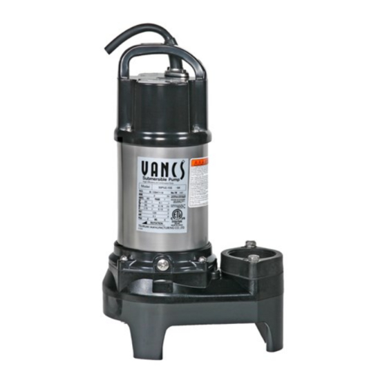
Page 5: Part Names
2 PART NAMES Example: PU Series Cabtyre Cable Mechanical Seal Oil Plug Oil Lifter Impeller Oil Casing Screwed Flange Air Release Valve Pump Casing Example: PN Series Cabtyre Cable Mechanical Seal Oil Plug Oil Lifter Impeller Oil Casing Screwed Flange... -
Page 6: Prior To Use
Do not operate this product under any conditions other than those that have been specified. Major Standard Specifications PU Series: Water, waste water, sewage, and liquid carrying waste and solid Consistency matters; 0 ~ 40°C PN Series: Water, waste water and effluent; 0 ~ 40°C... -
Page 7: Installation
4 INSTALLATION CAUTION • Do not use the pump for pumping liquids other than water, such as oil, salt water (TM Series excepted), or organic solvents. • Use with a power supply voltage variation within ±10% of the rated voltage. •... - Page 8 Precautions During Installation WARNING When installing the pump, be mindful of the pump's center of gravity and weight. If the pump is not suspended properly, the pump may fall and break, which may lead to injury. CAUTION When installing or moving the pump, never suspend the pump by the cabtyre cable.
- Page 9 Attaching a Chain to Suspend the Pump Chain Refer to the illustration on the right in order to suspend the pump by a chain. (On a model with a 1.5kW power Washer (for 1.5kW) output, use a washer.) Shackle CAUTION Make sure that the chain does not Bolt become twisted during installation.
-
Page 10: Electrical Wiring
5 ELECTRICAL WIRING Electrical Wiring Work WARNING • All electrical work must be performed by an authorized electrician, in compliance with local electrical equipment standards and internal wiring codes. Never allow an unauthorized person to perform electrical work because it is not only against the law, but it can also be extremely dangerous. - Page 11 CAUTION • If it is necessary to extend the cabtyre cable, use a core size equal to or larger than the original. This is necessary not only for avoiding a performance drop, but to prevent cable overheating which can result in fire, electrical leakage or electrical shock.
- Page 12 Electrical Circuit Diagrams PU/PN/PSF/TM Series PU/PN/PSF/TM Series Non-Automatic Circuit Non-Automatic Circuit (Output 0.75kW maximum) Power Supply: Three-Phase Green Power Supply: Single-Phase (Green/Yellow) Green Ground Motor Coil W-Black (Green/Yellow) Ground Protector (Black) White Operating Motor Coil V-White Protector Capacitor (Blue) (Grey) Motor Coil U-Red Aux.
-
Page 13: Operation
6 OPERATION Prior to Operation (1) Once again, check the nameplate of the pump to verify that its voltage and frequency are correct. CAUTION Improper voltage and frequency of the power supply will prevent the pump from attaining its full potential, and may also damage the pump. Note: Verify the specs on the pump's nameplate. - Page 14 (3) Connect the pump to the pipe and submerge it in water. (4) Operate the pump for a short time (3 to 10 minutes) and perform the following checks: Using an AC ammeter (clamp), measure the operating current at U V W G the phases U, V, and W that are connected to the terminal board.
- Page 15 6-2 Automatic Operation Trial Operation A Type Equipped with floats to detect the water level and an internal control circuit, the automatic type (PUA, PNA, PSFA, TMA) pump can perform an automatic drainage operation alone by merely connecting its cable to a power supply. Connect the power and perform a trial operation as follows: Check float switch operation (1) Direct all the floats downward.
-
Page 16: Maintenance And Inspection
6-3 Automatic Alternating Operation Trial Operation The (PUW, PNW, or PSFW) automatic alternating type pump is used in conjunction with the (PUA , PNA, or PSFA) automatic type. Equipped with floats to detect the water level and an internal control circuit, it can perform an automatic alternating drainage operation by merely connecting its cable to a power supply. - Page 17 Daily and Periodic Inspection Interval Inspection Item Measuring the operating current To be within the rated current Daily Measuring the power voltage Power supply voltage variation = within ±10% of the rated voltage Measuring the insulation resistance Insulation resistance reference value = 1MΩ minimum Note: The motor must be inspected if the insulation resistance is considerably lower than the last inspection.
-
Page 18: Disassembly And Reassembly Procedure
For these opera- tions, contact the dealer where this equipment was purchased, or the Tsurumi sales office in your area. PU Series Disassembly Procedure Note: Before disassembling, be sure to drain the oil from the pump. - Page 19 Disassembly Diagram [Back-Pullout Construction] Hex Bolt [Pump Disassembly Diagram] Hex Bolt Pump Portion *Motor Portion Impeller O-Ring Spring Washer Impeller O-Ring Truss Screw Pump Casing Hex Bolt Screwed Flange Packing Hex Nut Note: The description of the disassembly diagram above may differ slightly in shape and con- struction depending on the model.
- Page 20 PN Series Disassembly Procedure Note: Before disassembling, be sure to drain the oil from the pump. (1) This pump has adopted a back-pullout construction. Therefore, by removing the four cross-recessed hex bolts ⑩ (or hex nuts on the 1.5kW model), the pump can be inspect- ed while the impeller ⑤...
- Page 21 PSF Series Disassembly Procedure Note: Before disassembling, be sure to drain the oil from the pump. (1) This pump has adopted a back-pullout construction. Therefore, by removing the four cross-recessed hex bolts ⑩ (or hex nuts on the 1.5kW model), the pump can be inspect- ed while the impeller ⑤...
- Page 22 TM Series Disassembly Procedure Note: Before disassembling, be sure to drain the oil from the pump. (1) This pump has adopted a back-pullout construction. Therefore, by removing the four cross-recessed hex bolts ⑩ (or hex nuts on the 1.5kW model), the pump can be inspect- ed while the impeller ⑤...
-
Page 23: Troubleshooting
9 TROUBLESHOOTING WARNING To prevent serious accidents, disconnect the power supply before inspecting the pump. Read this Operation Manual carefully before requesting repair. After re-inspecting the pump, if it does not operate normally, contact the dealer where this equipment was pur- chased, or the Tsurumi sales office in your area.
Need help?
Do you have a question about the PU Series and is the answer not in the manual?
Questions and answers