Table of Contents
Advertisement
Advertisement
Table of Contents

Related Manuals for Daikin DCS303A51


Summary of Contents for Daikin DCS303A51
- Page 1 OPERATION MANUAL RESIDENTIAL CENTRAL REMOTE CONTROLLER MODELS DCS303A51...
-
Page 2: Table Of Contents
CONTENTS The precautions described herein are classified as WARNING and CAUTION. They both contain impor- tant information regarding safety. Be sure to PRE-OPERATION CHECK AND PRE- observe all precautions without fail. CAUTIONS SAFETY CONSIDERATIONS........1 WARNING ..Failure to follow these instructions SYSTEM OVERVIEW .......... -
Page 3: Cautions
Consult your local dealer regarding what to do in Be sure to use a dedicated power supply for the air case of refrigerant leakage. conditioner. When the air conditioner is to be installed in a small The use of any other power supply may cause heat room, it is necessary to take proper measures so that generation, fire, or product failures. - Page 4 Do not install the air conditioner at any place where there is a danger of flammable gas leakage. In the event of a gas leakage, build-up of gas near the air conditioner may result in fire hazards. Do not put flammable containers, such as spray cans, within 1 m from the blow-off mouth.
-
Page 5: System Overview
SYSTEM OVERVIEW This central remote controller can monitor and control up to 16 “indoor unit groups”. By using eight units of this central remote controller, maximum of 128 “indoor unit groups” can be monitored and controlled. Main Functions 1. Simultaneous ON/OFF control of all indoor units connected to the central remote controller. 2. -
Page 6: Names And Functions Of The Operating Section
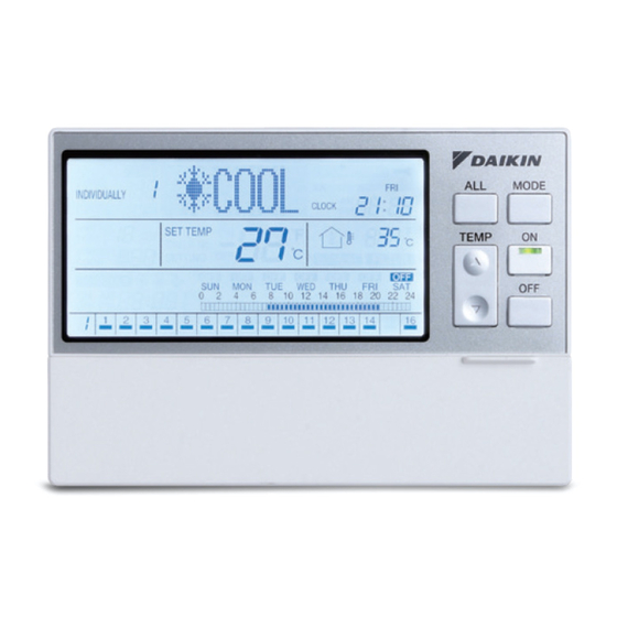
NAMES AND FUNCTIONS OF THE OPERATING SECTION External View (All indications are displayed in the following diagram of screen for the explanation purpose. Actual indications displayed during operation will vary.) 12 3-3 8 13 OUTDOOR TEMP DISPLAY This indicates that the display shows the ALL screen. In the ALL screen, this displays the outside tempera- ture detected by the outdoor unit connected to the air INDIVIDUALLY... -
Page 7: Screens
NAMES AND FUNCTIONS OF BUTTONS THE OPERATING SECTION Used to select a menu. CLOCK BUTTON Names of Operation Buttons Changes the display to the current time setting screen. SET/CANCEL BUTTON Enters or cancels settings. BUTTONS Used to set an operation schedule or current time. SCREENS HOW TO DISPLAY THE ALL SCREEN... -
Page 8: How To Display The Individually Screen
C. This section displays the Nos. of all connected air When an unconnected air conditioner conditioners (groups). (group) is selected indication lights under the Nos. of air con- ditioners that are operating. D. “System Down” is indicated when all air condition- ers in the system are in non-operation. -
Page 9: How To Turn All Units On Or Off Simultaneously
HOW TO TURN ALL UNITS ON Stopping all connected units OR OFF SIMULTANEOUSLY Turning on all connected units [Operating Procedure] 1. Press the ALL button (1) to display the ALL screen. 2. Press the OFF button (2) to stop all connected air [Operating Procedure] conditioners (groups). -
Page 10: How To Turn Units On Or Off Individually
HOW TO TURN UNITS ON OR Turning Off specific connected air con- ditioners OFF INDIVIDUALLY Turning On specific connected air con- ditioners [Operating Procedure] 1. Select an air conditioner (group) using one of the individual group selection buttons (1) (1 - 16) to display the INDIVIDUALLY screen. -
Page 11: How To Change The Operation Mode
HOW TO CHANGE THE OPERA- TION MODE Changing the operation mode of all connected air conditioners B. Each time the MODE button (2) is pressed, the operation mode of all connected air conditioners (groups) changes in the following sequence. COOL HEAT Changing the operation mode of spe- cific connected air conditioners... -
Page 12: How To Adjust The Set Temperature
[Screen Display] [Operating Procedure] 1. Press the ALL button (1) to display the ALL screen. 2. Each time one of the TEMP buttons (2) is pressed, the set temperature changes. Press the button to raise the set temperature by 1°C. Press the button to lower the set tempera- ture by 1°C. -
Page 13: Operation Code
D. If you do not want to set the temperature in all con- nected air conditioners (groups), set the set tem- perature to “--”. The “--” indication appears after pressing the button to raise the set temperature to the highest temperature setting and pressing the button one more time. - Page 14 3. Select OPERATION CODE to display the opera- B. The Function Menu appears. The Function Menu tion code setting screen. changes as follows when the button (2) is pressed. 4. Using the ALL button (5) or one of the individual group selection buttons (6) (1 - 16), select the air OUTDOOR OPERATION...
- Page 15 F. Press the SET/CANCEL button (3) once to com- G. The operation code indication blinks for 3 seconds plete the operation code setting procedure. and changes to constantly On. Then, the display The operation code indication blinks for 3 seconds returns to the ALL screen if the setting was made and changes to constantly On.
-
Page 16: Reset Filter Sign
Operation performed from remote controller Operation All ON by central All OFF by central Control mode Temperature Operation Code remote controller, remote controller, setting mode setting individual ON, ON by individual OFF, OFF timer by timer Permit Prohibit Prohibit Prohibit Remote Prohibit Permit Controller... - Page 17 * When the SET/CANCEL button is held pressed for more than 4 seconds, the Filter sign will be reset in all units. 5. If no button is operated for 1 minute or the FUNC- TION button (1) is pressed, the display returns to the ALL screen when the setting was made in the ALL screen, or to the INDIVIDUALLY screen when the setting was made in the INDIVIDUALLY...
-
Page 18: Outdoor Temperature Display
OUTDOOR TEMPERATURE DISPLAY Displaying the temperature of the out- door unit connected to the selected air conditioner F. The Filter sign in the selected air conditioner has been reset. G. To reset the Filter sign in all units, hold the SET/ CANCEL button pressed for more than 4 seconds. -
Page 19: Daylight Saving
[Screen Display] D. The Outdoor Temp Display setting screen appears. If no button is pressed for 2 seconds while the dis- play shows screen C to screen E on page 18, a guidance message, “ BUTTONS: CHANGE FUNCTION, BUTTONS: DISPLAY ON/OFF, SET/CANCEL BUTTON: SET,”... - Page 20 [Operating Procedure] 1. While the ALL or INDIVIDUALLY screen is dis- played, press the FUNCTION button (1) once. 2. The Function Menu appears. The Function Menu changes as follows when the button (2) is pressed. OUTDOOR OPERATION RESET TEMP CODE FILTER SIGN B.
-
Page 21: How To Set A Daylight Saving Period
I. When the daylight saving period ends, the clock moves back 1 hour, and the “DAYLIGHT SAVING” indication disappears. HOW TO SET A DAYLIGHT SAV- ING PERIOD Setting the start day and end day of E. Using the button, enable or disable the daylight saving period Daylight Saving function. - Page 22 5. Press the button (2) to select the input set- ting for the selected start/end day of daylight sav- ing period. SET START MONTH SET START WEEK SET HOUR SET DAY OF THE WEEK 6. Using the button (4), enter the daylight saving period.
- Page 23 E. Press the SET/CANCEL button (3) to display the H. Press the button (2) to select the input set- menu screen for setting the daylight saving period. ting for the start day of the daylight saving period. Press the button (2) to select the start day SET START MONTH SET START WEEK of the daylight saving period.
- Page 24 L. Using the button (4), set the week of the P. Press the button (2) to select the input set- daylight saving start day. ting for the daylight saving start time. Pressing the button advances the week indica- tion. Pressing the button reverses the indica- tion.
- Page 25 T. The display returns to the setting screen for the C. The Function Menu changes as follows when the daylight saving period. button (2) is pressed. To continue setting the end day of the daylight sav- OUTDOOR ing period, see E on page 24. OPERATION RESET TEMP...
- Page 26 I. Using the button (4), select the month of F. If no button is operated for 2 seconds in screen F, the daylight saving end day. a guidance message, “ BUTTONS: START/ Pressing the button advances the month indica- END, SET/CANCEL BUTTON: SET,” appears. tion.
- Page 27 M. Press the button (2) to select the input set- Q. The display changes to the input setting screen for ting for the day of the week of the daylight saving the daylight saving end time. end day. R. Using the button (4), set the daylight sav- N.
-
Page 28: Contrast Setting
NOTE 1. In each of steps 2 through 4, if no button is operated for 1 minute, the display returns to the ALL screen when the adjustment was made in the ALL screen, or to the INDIVIDUALLY screen when the adjust- ment was made in the INDIVIDUALLY screen. -
Page 29: Key Lock Setting
KEY LOCK SETTING Disabling operation buttons D. The Contrast setting screen appears and indicates the current contrast level. If no button is operated for 2 seconds while the dis- play shows screen C to screen E on page 27, a guidance message, “... - Page 30 [Screen Display] D. While the Key Lock Menu screen is displayed, press the SET/CANCEL button (3) once. mark blinks for 2 seconds and changes to constant On. The key lock is set, and the display returns to the ALL screen if the setting was made in the ALL screen, or to the INDIVIDUALLY screen if the setting was made in the INDIVIDUALLY screen.
-
Page 31: Schedule Setting
H. The key lock is cancelled, and the display returns 9. If no button is operated for 1 minute or the SCHED- to the ALL screen if the key lock was cancelled in ULE button (1) is pressed, the display returns to the the ALL screen, or to the INDIVIDUALLY screen if ALL screen when the setting was made in the ALL the key lock was cancelled in the INDIVIDUALLY... - Page 32 C. Using the ALL button (3) or one of the individual group selection buttons (4) (1 - 16), select the air conditioner (group) to be set. * If the timer is set in the ALL screen, the setting will apply to all air conditioners (groups). G.
- Page 33 J. If no button is operated for 1 minute or the SCHED- C. Using the ALL button (3) or one of the individual ULE button (1) is pressed once, the display returns group selection buttons (4) (1 - 16), select the air to the ALL screen when the setting was made in conditioner (group) to be set.
-
Page 34: Schedule Setting - "Off Day" Setting
F. Press the SET/CANCEL button (6) once to apply the setting. The Timer No. (7) and “day of the week” indica- tions change from blinking to constant On, and the set time indication blinks. When the SET/CANCEL button (6) is pressed once again, the display returns to screen D (blink- ing Timer No. - Page 35 8. If no button is operated for 1 minute or the SCHED- ULE button (1) is pressed, the display returns to the ALL screen when the setting was made in the ALL screen, or to the INDIVIDUALLY screen when the setting was made in the INDIVIDUALLY screen.
- Page 36 [Screen Display: “OFF DAY” SETTING Cancellation] G. Select “OFF DAY” SETTING, and press the SET/ CANCEL button (5) once to apply the setting. A. While the ALL or INDIVIDUALLY screen is dis- played, press the SCHEDULE button (1) once. H. After the “OFF DAY” SETTING is completed, the time indication on the schedule bar graph turns off.
-
Page 37: Schedule Setting: Copy Prev Day'ssetting
3. Using the ALL button (2) or one of the individual group selection buttons (3) (1 - 16), select the air conditioner (group) to be set. 4. Press the button (4) to select the day of the week to which the setting of the day before is to be copied. - Page 38 B. The Schedule setting screen appears. If no button is operated for 2 seconds while the dis- play shows screen B to screen D on page 36, a guidance message, “ BUTTONS: SELECT TIMER No., BUTTONS: SELECT DAY OF THE WEEK, SET/CANCEL BUTTON: SET,” appears and scrolls in the operation mode display section (dot matrix).
-
Page 39: Schedule Setting: Clear Timer
I. If no button is operated for 1 minute or the SCHED- 9. If no button is operated for 1 minute or the SCHED- ULE button (1) is pressed once, the display returns ULE button (1) is pressed, the display returns to the to the ALL screen when the setting was made in ALL screen when the setting was made in the ALL the ALL screen, or to the INDIVIDUALLY screen... - Page 40 D. Using the button (2), select the day of the G. Press the button (3) to select CLEAR week for which the schedule setting is to be TIMER. cleared. TIMER SETTING OFF DAY CLEAR TIMER COPY PREV DAY’S SETTING E. Using the button (3), select TIMER ON or TIMER OFF and a Timer No.
-
Page 41: Current Time Setting
CURRENT TIME SETTING [Screen Display] Setting the current day of the week and the current time A. While the ALL or INDIVIDUALLY screen is dis- played, press the CLOCK button (1) once. [Operating Procedure] 1. Press the CLOCK button (1) once while the ALL B. -
Page 42: Standby Mode
D. When the button (2) is pressed, the setting item changes. Select an item to set. YEAR MONTH/DAY TIME * This manual describes the methods of setting 1. YEAR, 2. MONTH/DAY and 3. TIME in that order. I. Pressing the button (3) increments the time indi- cation. -
Page 43: Outdoor Temperature Display
[Operating Procedure] OUTDOOR TEMPERATURE 1. Hold the OFF button (1) pressed for more than DISPLAY 10 seconds while the ALL screen or INDIVIDU- ALLY screen is displayed. Displaying the outside temperature 2. The LCD turns Off and the standby mode (energy- detected by the outdoor unit con- saving mode) will be activated. - Page 44 B. In the case of the ALL screen, the display shows E. During cooling operation, if the room temperature the outdoor temperature detected by the outdoor is lower than the set temperature, the outdoor tem- unit connected to the air conditioner (group) with a perature display remains fixed for 30 minutes, and cooling/heating selection privilege (*) that has the it changes to “--”.
-
Page 45: Error Diagnostic Function
H. During heating operation, if the room temperature [About the Error Diagnosis Function] is higher than the set temperature, the outdoor The Central Remote Controllers is equipped with a temperature display remains fixed for 30 minutes, diagnostic function that analyzes the cause of an error and the temperature display changes to “--”. - Page 46 Indoor unit · Drain level error (33H) Indoor unit · Fan motor (51F) lock, overload Indoor unit · Fan direction adjustment motor (MA) error Indoor unit · Fan direction adjustment motor error Indoor unit · BEV unit, electric expansion valve motor (20E) error Indoor unit ·...
- Page 47 Outdoor unit · Heat exchange thermistor (Th2) error Error (faulty connection, cut wire, short circuit, fault) Outdoor unit · Header thermistor (Th6) error Outdoor unit · Oil pressure equalizer thermistor error (faulty con- nection, cut wire, short circuit, fault) Outdoor unit · Double-pipe heat exchanger outlet thermistor error (faulty connection, cut wire, short circuit, fault) Outdoor unit ·...
-
Page 48: Cooling/Heating Privilege Setting
Incorrect combination of indoor, BS, and outdoor units within a single system (model, number of units, etc.) Incorrect combination of indoor unit and remote controller (remote controller in question) BS unit connection position fault Central control group numbers overlap Transmission error between indoor unit and central controller Unset system, incorrect settings between BEV unit and indoor unit System fault... -
Page 49: Specifications
SPECIFICATIONS Specifications Power supply 50/60Hz, 200V - 240V Power consumption Max. 3W Continuous a contact Forced OFF input Contact current: approx. 10 mA Size 180 (W) × 122 (H) × 63 (D) B. Hold the MODE button (3) pressed for more than Weight 530g 4 seconds. -
Page 50: After-Sale Service
AFTER-SALE SERVICE About After-sale Service WARNING Do not attempt to disassemble, modify or repair the product. Electrical shock or fire may result if you attempt to disassemble, modify or repair the product yourself. Request your dealer when the product Prohibit needs repair. - Page 51 3P124623-10N EM07A058A (0802) HT...
Need help?
Do you have a question about the DCS303A51 and is the answer not in the manual?
Questions and answers