
Related Manuals for ShinewayTech MTP-200 Series


Summary of Contents for ShinewayTech MTP-200 Series
- Page 1 MTP-200 Series Multifunctional Test Platform User’s Manual Shineway Technologies, Inc. All rights reserved.
- Page 2 MTP-200 Series Multifunctional OTDR Test Platform...
-
Page 3: Warranty
Warranty The material contained in this document is subject to change without notice. ShinewayTech makes no warranty of any kind with regard to this material, including, but not limited to, the implied warranties of merchantability and fitness for a particular purpose. ShinewayTech shall not be liable for errors contained herein or for incidental or consequential damages in connection with furnishing, performance, or use of this material. - Page 4 MTP-200 Series User’s Manual impaired if it is used in a manner not specified in the operation instrument. Environmental Conditions It is designed to operate at a maximum relative humidity of 95% and at altitudes of up to 2000 meters. Refer to the specifications tables.
-
Page 5: Laser Safety Announcements
MTP-200 Series User’s Manual The NOTE sign information that may be beneficial during the use and maintenance of MTP-200. Laser Safety Announcements MTP-200 is a laser instrument. Users should avoid looking directly into the optic output. ➢ Always avoid looking directly into the optical output port, when MTP-200 is working. -
Page 6: Agreement And Statement
MTP-200 Series User’s Manual Agreement and Statement Button or menu: The operating units in GUI that can be clicked by stylus, indicated by letters in square brackets, e.g. [Setup] and [Start]. Key: The function key on front panel, indicated by letter or icon in quotation marks, e.g. -
Page 7: Table Of Contents
MTP-200 Series User’s Manual Contents Notices ..........................iii Warranty ..........................iii ISO9001 Certification ......................iii Safety Instructions ....................... iii Laser Safety Announcements ....................v Electric Safety Announcements ................... v Agreement and Statement ....................vi 1 General Information ......................1 1.1 Scope of this Manual ..................... 1 1.2 Introduction ........................ - Page 8 MTP-200 Series User’s Manual 4.1 Principle of OTDR Module ..................17 4.2 Measurement Application of OTDR................18 4.3 Basic Definition and Classification of Events ............. 18 4.3.1 Reflection Events ..................18 4.3.2 Non-reflection Events ................19 4.4 Optic Fiber Link and Event Types ................19 5 Instruction of OTDR Modules of MTP-200 ..............
- Page 9 MTP-200 Series User’s Manual 9.2 OTDR test parameters Configuration ................34 9.3 OTDR display and other Configuration ..............35 9.4 Real time and average test mode ................. 35 9.5 Range Configuration ....................36 9.6 Pulse Width Configuration ..................36 9.7 Averaging Time Configuration ..................37 9.8 Laser Wavelength Configuration .................
- Page 10 MTP-200 Series User’s Manual 11.14.4 Delete event ..................53 11.15 Analysis Detecting Threshold Configuration............54 11.16 Reanalyze the Trace ....................55 11.17 Analyze the Optical Fiber in Specific Optical Fiber Link ........56 11.18 Set Trace Display Parameter ..................56 11.19 Set the Length Unit ....................
- Page 11 21 Troubleshooting ......................87 21.1 Common Problems and Solutions ................87 21.2 Trace Measurement Problems and Solutions ............. 88 21.3 Finding Information on ShinewayTech Website ............88 22 Warranty ......................... 89 22.1 Terms of Warranty ..................... 89 22.2 Exclusion ........................89 22.3 Warranty Registration ....................
- Page 12 MTP-200 Series User’s Manual Fig. 1.1 Front View ........................2 Fig. 1.2 Front View ........................3 Tab. 1.1 Front Panel Indicators Introduction ................3 Tab. 1.2 Front Panel Keys Instruction ..................4 Tab. 1.3 Operating Parts Instructions ..................5 Tab. 1.4 nterfaces on Platform Top ..................6 Tab.
- Page 13 MTP-200 Series User’s Manual Fig. 11.3 Add event ....................... 51 Fig. 11.4 Add Event Dialog Window ..................52 Fig. 11.5 Modify events ......................53 Fig. 11.6 Modify Event......................53 Fig. 11.7 Delete Event ......................54 Fig. 11.8 Parameters analysis edit frame ................55 Fig.
-
Page 14: General Information
MTP-200, troubleshooting instructions as well as information regarding obtaining services. 1.2 Introduction MTP-200 series are the compact multi-functional platform. It is convenient and accurate for auto/manual testing, multi-wavelength testing, Integrated intelligent and multi-functional analysis. MTP-200 is easy to handle with large color LCD touch screen and smart user-interface. -
Page 15: Product Appearance
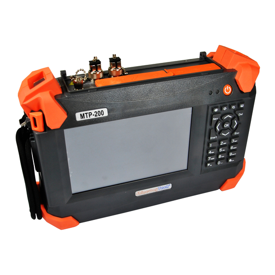
MTP-200 Series User’s Manual ➢ RC100: Remote control Module ➢ LM100: Link Image Module 1.3 Product Appearance Charging Indicator Front View Power Indicator Power on/off button Help Direction/Enter Keys Return Button Start/Stop LCD Touch Screen Hand belt Fig. 1.1 Front View Power On/Off key is lower than other keys to avoid misoperation. -
Page 16: Front Panel Indicators Introduction
MTP-200 Series User’s Manual Top View OTDR Port DC IN Port VFL Port USB Host x2 Laser Warning USB Slave Lights OCI Port RJ-45 Port Fig. 1.2 Front View 1.4 Front Panel Indicators Introduction Icon Status Meaning System off Green, constant... -
Page 17: Operating Parts Instructions
MTP-200 Series User’s Manual Name Function Start/Stop Launch selected module in main interface. Back Move up or extended function to be defined, please refer to Help of current interface. Move down or extended function to be defined, please refer Help of current interface. -
Page 18: Instrument Interfaces Instructions
MTP-200 Series User’s Manual Name Operation Description trace. Click and 1. Open menu or select in File Explorer. hold 2. Select object in other windows. Left click Left double Mouse click Similar to stylus, more convenient for (Optional) desktop application. - Page 19 MTP-200 Series User’s Manual Name Appearance Icon Description Connection to the OCI OCI Port (Optical Connector Inspector) system adjustment Serial Interface (Not open to user) Audio Port Audio output/input Tab. 1.4 nterfaces on Platform Top · Optical Ports MTP-200 is equipment with FC/PC connectors (Interchangeable SC, ST and LC)
-
Page 20: Gui Icons Instruction
MTP-200 Series User’s Manual MTP-200 is a laser instrument. Users should avoid looking directly into the optic output. And the use of microscope or magnifier should also be avoided, for the use of such devices can focus a highly intense beam onto the retina, which may result in permanent eye damage. -
Page 21: Power Instruction
MTP-200 Series User’s Manual Tab. 1.6 GUI Icons Instruction 1.9 Power Instruction MTP-200 uses following power supplies: ➢ AC adaptor (Connect to standard outlet – Indoor use only) ➢ Li-ion rechargeable battery (Auto power supply when AC adaptor is unplugged) ➢... -
Page 22: Basic Operation
MTP-200 Series User’s Manual Keep the battery off from fire and intense heat; do not open or short circuit the battery. 2 Basic Operation 2.1 Foreword This part introduces the basic operation on the MTP-200. Please read this manual carefully for optimal operation. -
Page 23: Adjust Lcd Brightness
MTP-200 Series User’s Manual Exit power saving mode: ➢ Press (Power) button , LCD backlight will turn on; ➢ Or press any key on the front panel; ➢ Or click the touch screen with stylus; ➢ Or click mouse. 2.4 Adjust LCD Brightness The LCD lightness is 4-level adjustable. -
Page 24: Install Usb Keyboard/Mouse
MTP-200 Series User’s Manual Fig. 2.1 Main Interface Launch OTDR program: 1. Select “Modules” label and then “OTDR Module” in main menu, the part will be highlighted. 2. Then click [Start] to start program. Launch Multifunctional module or optical connector inspector module application program: 1. -
Page 25: Printer Configuration
MTP-200 Series User’s Manual 2.7 Printer Configuration Must configure a printer before printing the trace or report. Procedure: 1. Turn on printer power. 2. Use USB cable to connect MTP-200 and printer 3. Enter OTDR interface 4. Click the [ ] on the lower right corner, enter Print interface, as Fig. -
Page 26: Common Settings And Special Settings
MTP-200 Series User’s Manual Fig. 2.3 Printer setting interface 6. In the printer list, choose the printer relative; chose “LPT1:”in the port list. Other options default is ok. 7. After right selection, click “OK” to finish the printer configuration. ◆ MTP-200 only support USB port printer with PCL language; till now the printers passed the test are HP LaserJet 1022 and Hp Laser P2015d etc. -
Page 27: Select Language
MTP-200 Series User’s Manual Fig 3.1 Main Setting Menu 3.2 Select language Switching language: Click [Setup] to enter into setting menu. In language area, choose the requiring language. Press “OK” to confirm modification 3.3 Automatic Power Saving Setting The feature is designed to save the battery power. -
Page 28: Recalibrate Touch Screen
MTP-200 Series User’s Manual Power saving mode is on by default, and LCD backlight turn off automatically in 10 minutes. 3.4 Recalibrate Touch Screen If touch screen is abnormal, you should recalibrate it. Recalibrate touch screen: Click [Setup] to enter into setting menu. -
Page 29: Serious Deviation Of Touch Screen
MTP-200 Series User’s Manual 3.5 Serious Deviation of Touch Screen When deviation of touch screen is serious, it is difficult to calibrate only using stylus. You can use USB mouse to enter into calibration window, and continuing to calibrate with pen. -
Page 30: Load Default
MTP-200 Series User’s Manual 3.8 Load Default This function is used to set system settings to factory default. Those parameters include: Interface style, language, power saving and OTDR features. Load default: 1. In main interface, click [Setup]. 2. In setting menu, click [Load Default], system promotes a warning message: “Restore factory settings?”... -
Page 31: Measurement Application Of Otdr
MTP-200 Series User’s Manual between two media of different IOR (For example, connections of faults, connectors, or optic fiber end). This reflection is used to locate the discontinuous points on optic fiber. The magnitude of reflection depends on the difference between IOR and the smoothness of boundary. -
Page 32: Non-Reflection Events
MTP-200 Series User’s Manual occurs, peak shows on trace, as shown below: Fig.4.1 Reflection Event 4.3.2 Non-reflection Events Non-reflection events happen at certain points where there is some optic loss but no light scattering. When non-reflection event occurs, a power decline shows on trace, see below: Fig.4.2 Non-reflection Event... -
Page 33: Instruction Of Otdr Modules Of Mtp-200
MTP-200 Series User’s Manual Tab.4.1 Optic fiber link and event type End of optic fiber can be identified through scanning the first loss event that is greater than end threshold. 5 Instruction of OTDR Modules of MTP-200 5.1 Main Features of OTDR Module ➢... -
Page 34: Averaging Mode And Realtime Mode
MTP-200 Series User’s Manual 5.2.2 Averaging Mode and Realtime Mode Realtime Mode: OTDR will undertake realtime measurement for the connector of exterior fiber and refurbish the measure trace. Under realtime mode, unless the user stops measurement, it will measure all along. -
Page 35: Otdr Interface
MTP-200 Series User’s Manual 5.3 OTDR Interface When power on, it will show the main menu automatically In main menu, select “OTDR module”, click [Start] button to enter OTDR user interface, as follows: Navigation Window Zoom Bar Trace Display Area... -
Page 36: Trace Processing
MTP-200 Series User’s Manual Icon Description Open trace file Print trace file Zoom in trace horizontally Zoom out trace horizontally Zoom in trace vertically Zoom out trace vertically Full-trace view A/B marker switch Move marker or marking point left/right Toggle between marking points... -
Page 37: Available Otdr Module
MTP-200 Series User’s Manual Trace processing includes: ➢ Trace editing (Single trace, multi traces) ➢ Printing (Single trace printing, batch printing) ➢ Trace reanalysis ➢ Trace format conversion Bi-directional averaging program (for single mode fibers only) is available in advanced versions to increase loss testing accuracy by averaging the measured loss values of each event from both directions. -
Page 38: Test With Otdr
MTP-200 Series User’s Manual Improperly connected fiber may cause serious loss and reflection. Please refer to Safety Instructions of this manual before testing to ensure personal safety. ◆ When testing with OTDR, unless connected to specific optical port, please make sure there is no working laser in the fiber under test or it may cause incorrect result and even permanent damage to test instrument. -
Page 39: Trace Processing
MTP-200 Series User’s Manual Fig. 7.1 OTDR Trace Acquisition Interface ◆ Click the [Start] button with stylus or mouse. ◆ During testing, the averaging trace shows in the trace display area and refresh at certain intervals, the trace after testing finishes is the final trace. -
Page 40: Unsaved Traces
MTP-200 Series User’s Manual Application will promote user to save unsaved trace before starting new test. 7.3 Unsaved Traces Unsaved traces will be titled as “*U_xxxx” (xxxx stands for the current testing wavelength) which is displayed on the left upper corner of trace display area. - Page 41 MTP-200 Series User’s Manual Fig. 7.2 Save dialog window ◆ Title shows current folder path, shown 7.2: “\SDMMC_DISK\Traces\”. ◆ System will automatically enter newly created folder. ◆ After file is saved, file name will be displayed on left upper corner of trace display area.
-
Page 42: Auto Naming
MTP-200 Series User’s Manual 7.5 Auto Naming System supports auto naming when saving traces. Procedure: 1. Enable/disable auto naming by checking/unchecking “Auto Naming” in OTDR Setup. 2. User can edit auto naming rule by modifying file name prefix, input the prefix in “File Name”... -
Page 43: Information And Function Windows
MTP-200 Series User’s Manual including loss, attenuation, reflection and etc. All of their operation can be realized by mouse or stylus. Zoom in/out trace: ➢ In trace display area, draw selection frame from left upper corner to right lower corner to zoom in trace. -
Page 44: Switch Information And Function Windows
MTP-200 Series User’s Manual Information includes: Event list, measurement parameters, markers information (A/B marker, marking points and etc.), trace parameters and trace information. Information and function windows description: Label Function Measurement parameters: Meas. Para. Mode, Wavelength, Range, Pulse Width, Averaging Time and etc. -
Page 45: Upload Trace To Pc
MTP-200 Series User’s Manual ◆ For more operation on events, please refer to “Trace Analysis and Event Operation”. 7.9 Upload Trace to PC On computer, user can manage the trace file flexibly. Copy or move the trace to computer: 1. User can copy the saved trace to computer via USB by PC software 2. -
Page 46: The Procedures Of Auto Testing Mode
MTP-200 Series User’s Manual After Auto mode started, according to the situation of optical fiber link which connecting the equipment, application program will estimate the optimum setting automatically and it will need around 5s. If the testing was cut off, any date won’t be displayed. -
Page 47: Common Using Parameters For Otdr Testing
MTP-200 Series User’s Manual and gets more ideal test result. Correct parameters setting is the essential condition of optical fiber accurate measurement. So, when test manually, must set parameters according to requirements. 9.1 Common using parameters for OTDR testing Following testing parameters displaying on {Meas. Para.} option card on the OTDR surface, users can set conveniently. -
Page 48: Otdr Display And Other Configuration
MTP-200 Series User’s Manual Parameter Definition Default Revert to the values when leave factory Tab. 9.2 OTDR test parameters setting sheet 9.3 OTDR display and other Configuration It is including setting of save method, testing display area and etc. Parameters setting in this part won’t affect the testing result. -
Page 49: Range Configuration
MTP-200 Series User’s Manual the result after the testing finished. Under general condition, user chooses average mode will be ok. Operating instructions ✓ Real time mode and average mode are controlled by [Real time/Average] in {test setting}<test mode>. ✓ When the button highlight display “Average”, it means average mode; when button sag and display “Real time”, it means real time mode. -
Page 50: Averaging Time Configuration
MTP-200 Series User’s Manual ◆ Default value: Auto ◆ When the distance range is “Auto”, the pulse width will be “Auto”, no need the user to set. ◆ There will be different pulse width options according to different distance range. -
Page 51: Ior Setting
MTP-200 Series User’s Manual For DWDM OTDR: Click in Wavelength parameter zone to select test wavelength in wavelength panel or click to select all wavelengths. Fig. 9.8b Laser wavelength configuration (DWDM OTDR) The effective wavelength will be different according to modules purchased. -
Page 52: Non-Reflection Threshold (Splice Loss Detecting Threshold) Setting
MTP-200 Series User’s Manual Configuration zone is -10 to -70dB 9.11 Non-reflection Threshold (Splice Loss Detecting Threshold) Setting This configuration has direct impact on the listing of insertion loss events. Only insertion loss event which is greater than this threshold will be listed. The value configuration zone is 0.00 to 5.00dB... -
Page 53: Load Default
MTP-200 Series User’s Manual 9.14 Load Default In OTDR Setup surface, there are 3 “default” button, corresponding to IOR, scatter coefficient (back scatter), non-reflection threshold (splice loss detecting threshold), reflection threshold (reflection detecting threshold) and end threshold (optical fiber end detecting threshold). -
Page 54: Test Parameter Recommendation Value
MTP-200 Series User’s Manual For normal optical fiber link, end threshold configuration can be 3.0dB, as to PON network optical fiber link with branching unit, it need to set the end threshold to a proper value and then MTP-200 can locate the end event correctly. Please refer to follow end threshold configuration sheet. -
Page 55: Simultaneous Display Multi Traces
MTP-200 Series User’s Manual navigator window zoom tool grid line Fig. 11.1 Trace file opened ◆ Check or open “.jpg” format trace file, please use the “File Explorer” in {Program}. ◆ Can’t open bidirectional trace file on instrument. If need to, use the bidirectional analysis program provided by MTP-Suite which installed on computer. -
Page 56: Close Trace File
MTP-200 Series User’s Manual System can open 4 traces at the same time. When need to open other traces, please close some opened traces. 11.3 Close Trace File Close trace file: Click [Close trace] button on the upper right corner of the interface to close the trace file. -
Page 57: Switch And Move Markers
MTP-200 Series User’s Manual Event Options: In {Event} options, there are various parameters of events listing, including event type, number, position, insert loss, reflection loss, attenuation and accumulation and etc. When switch to {Event}, application program will display a marker on the tracing graph. -
Page 58: Switch And Move The Marked Point
MTP-200 Series User’s Manual ◆ For easier using, the position of Markers will be remembered, when open MTP-200 and trace next time, the Markers will maintain the position operated last time. ◆ There is marked point when proceed the loss or reflection analysis. -
Page 59: Lock Ab Markers
MTP-200 Series User’s Manual 11.8 Lock AB Markers In the surface of {Markers}, press down [|A-B|], A and B Markers will be locked. After AB Markers locked, when moving one Marker, the other one will move with it and the distance maintains the same. -
Page 60: Use Zoom Toolbar To Zoom The Trace
MTP-200 Series User’s Manual ◆ The trace can’t be contracted more after contracted to 1:1 size. ◆ Application program will maintain the zoom situation for further test and check of similar trace. 11.11 Use Zoom Toolbar to Zoom the Trace On the right side of trace window, there is a zoom toolbar vertical ranked. -
Page 61: Zoom Out Trace Vertically
MTP-200 Series User’s Manual 11.11.5 Zoom out Trace Vertically Click [ ] to Zoom out trace vertically. 11.12 Remember the Zoom Status Automatically In the process of testing or opening trace, the magnified proportion and position will be remembered temporary. When test under the same distance once again, the magnified status of the window remain the same for continuous test. -
Page 62: Operation Of Event Options
MTP-200 Series User’s Manual In navigation window, if click the shadow region (display scope of magnified window), the operation invalid. Use direction keys to move trace window As to the magnified trace, press down the direction keys on the front panel, the trace window will move correspondingly. -
Page 63: Display The Event On The Trace And Locate Event In Even Sheet
MTP-200 Series User’s Manual Fig. 11.2 Events options As to every event in the even sheet, display follows info: ➢ Type: Different indicator used for different event type instruction. As to the detailed indicator instruction, please refer to the paragraphs previous. -
Page 64: Add Event
MTP-200 Series User’s Manual current window. ◆ It is better to locate event under whole trace status and then magnify to see the detail. 11.14.2 Add Event User can insert event into event sheet at any time manually. For example, when there is a splice point on some given position, but as it hidden in the noise or the splice loss lower than the minimum value of non-reflection detecting threshold, then the analysis didn’t test that... -
Page 65: Modify The Event
MTP-200 Series User’s Manual Fig. 11.4 Add Event Dialog Window 3. Press [Enter] to save and back to main window after edit finished, the event will appear in the event list. If pressed [Cancel], it will quit without save. There are reflection event and non-reflection event for inserted event. -
Page 66: Delete Event
MTP-200 Series User’s Manual Fig. 11.5 Modify events To modify the event information in the event modification popups. Fig. 11.6 Modify Event 3. Press [Enter] to save and back to main window after editing finished, the event will appear in the event list. If pressed [Cancel], it will quit without save. -
Page 67: Analysis Detecting Threshold Configuration
MTP-200 Series User’s Manual ➢ Starting point of the link ➢ End point of the link Important hint: The only way to recover the deleted items is to reanalyze the trace, like analyze new traces. Please refer to the part “analyze or reanalyze trace”. -
Page 68: Reanalyze The Trace
MTP-200 Series User’s Manual ➢ Change the finish threshold (optical fiber end threshold): It can analyze the important loss event (like breakpoint) and stop the event analysis after that event. “Auto” mode and “Manual” mode can use these thresholds. Set analysis detecting threshold 1. -
Page 69: Analyze The Optical Fiber In Specific Optical Fiber Link
MTP-200 Series User’s Manual ➢ Re-found the original event sheet (if the event sheet has been modified). Application program will analyze the newest tested trace. User can check the analytic result in the event options. Reanalyze the trace: 1. In the [Event] options, press [Analysis], it will reanalyze the whole trace;... - Page 70 MTP-200 Series User’s Manual ➢ Navigation window: It can display or hide the window which used for whole trace survey on the upper right position of the trace window. ➢ Length unit: it can select the length unit will be used in the whole application program.
-
Page 71: Set The Length Unit
MTP-200 Series User’s Manual 11.19 Set the Length Unit In the OTDR parameters setting dialog box, select the length unit in the test display area options. The unit can be meter, feet or mile. ◆ The default length unit is meter. - Page 72 MTP-200 Series User’s Manual ➢ File name: The name of current trace. ➢ Date: Date and time of test. ➢ Wavelength: Laser wavelength used for test. ➢ Pulse width: Laser pulse width used for sampling. ➢ Averaging time: Continuous sampling time.
-
Page 73: Manual Trace Analysis
MTP-200 Series User’s Manual 12 Manual Trace Analysis User can use markers and zoom tools to measure splice loss, attenuation and reflection, or use markers to locate event position and relative power level. 12.1 Use Markers Click {Markers} label in OTDR main interface to activate markers. -
Page 74: Measure Insertion Loss (2-Point And 5-Point Method)
MTP-200 Series User’s Manual 12.3 Measure Insertion Loss (2-point and 5-point method) Insertion loss (unit: dB) is calculated by measuring the signal level of Rayleigh backscatter (RBS) and the magnitude of reduction. Insertion loss can be created by reflection and non-reflection events. - Page 75 MTP-200 Series User’s Manual 5-point method to measure event loss: Event loss is measured by 5-point method. When the [Loss] button in “Markers” Label is not pressed, the marking points used by 5-point method will not display; however, the system use 5-point method by default.
- Page 76 MTP-200 Series User’s Manual 3. Zoom the trace to view the event clearly, move Marker A to the end of linear part of the trace before the event; 4. Move the first marking point to the beginning of the linear part of the trace before the event;...
-
Page 77: Measure Attenuation (2-Point And Lsa Method)
MTP-200 Series User’s Manual 12.4 Measure Attenuation (2-point and LSA method) 2-point method measures the attenuation between Marker A and B calculated by all the loss over the distance between Marker A and B (Unit: dB/Km). Use only these two points to calculate and the average value does not exist. -
Page 78: Measure Reflectance
MTP-200 Series User’s Manual 12.5 Measure Reflectance Reflectance is the ratio of reflected power (Pr) to incident power (Pi) of an event (such as a connector). Reflectance = 10 log (Pr/Pi). 1. Click {Markers} label in OTDR main interface to show Marker A and B. -
Page 79: Trace File Management
MTP-200 Series User’s Manual Fig 12.6 Measure reflectance For non-reflection events, reflectance will show as “-----”。 13 Trace File Management User can save, open, rename and delete trace file after acquisition. User can save and open trace file in OTDR main interface. -
Page 80: Copy, Move, Rename And Delete Trace
MTP-200 Series User’s Manual If saving trace as other formats, user should copy the trace file to the PC and use the OTDR Trace Manager of MTP-Suite, which has installed on the PC, to select other formats. 13.2 Copy, Move, Rename and Delete Trace There are two ways to copy, move, rename and delete trace. -
Page 81: Check Disk Space
MTP-200 Series User’s Manual 13.3 Check Disk Space User can check disk space utilization status (used space and free space) in File Explorer: 1. Enter File Explorer in MTP-200 main interface. 2. Click “SDMMC_Disk” icon and select [File] <Properties> or click and hold “SDMMC_Disk”... -
Page 82: Check And Edit Trace Information
MTP-200 Series User’s Manual Adding or updating the information can be completed in {Trace Info.}. 14.2 Check and Edit Trace Information User can check and edit trace information in {Trace Info.} function window. When newly tested trace is saved, the trace is saved with above information. -
Page 83: Print Otdr Report
MTP-200 Series User’s Manual Fig. 14.2 Edit trace information 4. After editing, press [Ok] to save and return to main interface; click [Cancel] to leave without change. 5. Click [Save] button in OTDR main interface to save the trace again and the updated information will be saved with the trace file. - Page 84 MTP-200 Series User’s Manual Print OTDR report: 1. Connect USB printer to MTP-200. For first printing, please first configure printer, please refer to 2.7 Printer Configuration. 2. Click [ ] button in OTDR main interface and printing dialog window will pop up.
- Page 85 MTP-200 Series User’s Manual Fig. 14.4 Printing options 5. Press [Print] button to start printing. During printing, system will promote a message as “Printing…Pease wait”, shown in Fig 14.5. Fig. 14.5 Printing 6. After printing is finished, system will return to main interface.
-
Page 86: Otdr Module Built-In Stabilized Laser Source Ls100
MTP-200 Series User’s Manual 15 OTDR Module Built-in Stabilized Laser Source LS100 Under “Source”, interface is shown as Fig 15.1 Fig.15.1 “Wavelength”: Same as the wavelength of OTDR, wavelengths can be selectable. “Modulation”: Select different modes at CW, 270Hz, 1KHz, 2KHz、Auto ID. -
Page 87: Otdr Module Built-In Optical Power Meter Pm100
MTP-200 Series User’s Manual 16 OTDR Module Built-in Optical Power Meter PM100 Optical power meter operation: Click “OPM” icon to enter Optical Power Meter interface as shown in Fig 16.1. Fig. 16.1 Optical Power Meter After the setup, click [Start] button to start the measurement. Click [Stop] button to stop the measurement. - Page 88 MTP-200 Series User’s Manual Put protective cap on optical power testing output, and ensure that the tie-in is completely airproof. “Wavelength”: Support 850, 1300, 1310, 1490, 1550, 1625, 1650nm wavelengths selectable. PM100 is only available with the OTDR module built-in PM100. With PM100, OTDR port will issue a special modulation signal.
-
Page 89: Vfl Application
MTP-200 Series User’s Manual 17 VFL Application The built-in VFL of OTDR module can shoot red laser into the tested fiber, the red laser will glow at the marco bend, breaking points and bare fiber end. The maximum detection range for MTP-200 VFL is over 5Km, it is a practical tool for fiber identification, detecting and highlighting breaks, tight bends, splices or defective connectors in optical fibers. -
Page 90: Oci (Optical Connector Inspector) Of Mci100
MTP-200 Series User’s Manual Fig. 17.1 VFL operation 18 OCI (Optical Connector Inspector) of MCI100 MCI100 Optical Connector Inspector (OCI) can display connector surface enlarged view and find dirty or damaged connector. It is convent for the operator to view the connector and remove any hidden troubles,which may affect the transmission quality. - Page 91 MTP-200 Series User’s Manual Fig. 18.1 Optical Connector Inspector Interface 4. Click [Start] button or Press “ ” (Start/Stop) button on MTP-200 front panel to start the measurement. As shown in Fig 18.2 Shineway Technologies, Inc. - 78 -...
-
Page 92: Adjust The Image' Brightness And Contrast
MTP-200 Series User’s Manual Fig. 18.2 Measurement 5.Click [Stop] button or Re-Press “ ”(Start/Stop)button on MTP-200 front panel to stop the measurement. 6. Exit this OCI interface: Click the exit button in the upper left corner; it will back to the main interface. -
Page 93: Focus Control
MTP-200 Series User’s Manual 18.3 Focus Control Control the focus by the focus control knob in the probe. 18.4 Zoom Image Press [Zoom In] button, the image will magnify double. In the magnification status, press [Zoom Out] button, the image will recover the original size. -
Page 94: File Management
MTP-200 Series User’s Manual 19 File Management User can directly copy, move, rename and delete file or folder on MTP-200. Files can also be exchanged between MTP-200 and external storage devices like USB flash disk, USB hard drive and PC. -
Page 95: Transfer Files Or Folders Between Mtp-200 And Pc
MTP-200 Series User’s Manual 19.2 Transfer Files or Folders between MTP-200 and PC Microsoft ActiveSync software must be installed first on PC for file transfer between MTP-200 and PC. Some necessary software shall be installed on PC before connecting MTP-200 to PC. For more information about installation, please refer to the instructions in software setup CD. -
Page 96: Delete Saved Files
MTP-200 Series User’s Manual 19.3 Delete Saved Files 1. Click File Explorer icon on {Program} label to enter File Explorer. 2. Click “\SDMMC_Disk” icon to enter internal storage space. 3. Select the files or folders to be deleted. 4. Click “Delete” in “File” menu to delete. -
Page 97: Cleaning Tools
MTP-200 Series User’s Manual Be cautious of electric shock and make sure AC power is disconnected with MTP-200 before cleaning. Always use dry or moist soft cloth to clean the outside of MTP-200, and never clean the inside Please do not add any accessory to optic instrument or adjust MTP-200 at discretion. -
Page 98: Battery Instruction
MTP-200 Series User’s Manual 2. Front panel charging indicator ( ) also indicated charging status (Please refer to 1.4 Front Panel Indicators Introduction). 20.7 Battery Instruction ◆ New battery is not fully charged, please charge the battery before the first time use which takes approximately 3 hours. -
Page 99: Change Battery
MTP-200 Series User’s Manual Procedure: 1. Run out of the battery completely. 2. Charge the battery until fully charged. 20.10 Change Battery 1. Power Off MTP-200 and unplug power adaptor. 2. Open the battery dock cover. 3. Change battery. 4. Close the battery dock cover. -
Page 100: Troubleshooting
MTP-200 User’s Manual 21 Troubleshooting 21.1 Common Problems and Solutions Problem Possible Reason Solution ◆ Charge the battery. ◆ Change a new battery. Battery power run out ◆ Connect MTP-200 to external power supply. Power on failure External power supply Connect MTP-200 to external power is not connected supply. -
Page 101: Trace Measurement Problems And Solutions
ShinewayTech (www.shinewaytech.com) provides FAQ (Frequency Asked Questions) about the MTP-200. 1. Type http://www.shinewaytech.com in the address bar of browser. 2. Press the [Service and Support] TAB COBTROL. . 3. Click the FAQ, and then Associated with searchable list of questions. -
Page 102: Warranty
22 Warranty 22.1 Terms of Warranty All ShinewayTech products are warranted against defective material and workmanship for a period of one (1) year from the date of shipment to the original customer. Any product found to be defective within the warranty period would be repaired or replaced by Shineway Technologies Inc. -
Page 103: Contacting Customer Service
Be sure to ship to our local representative or directly to us in a reliable way. 22.5 Contacting Customer Service Please check our web site (www.shinewaytech.com) for updates to this manual and additional application information. If you need technical or sales support, please contact local Shineway Technologies Customer Service. -
Page 104: Product Information
MTP-200 User’s Manual Product Information: Instrument: MTP-200 Standard Package Name Qty. Host Data Cable ithium Battery Carrying Case Software Warranty card Calibration Certificate Optional Name Qty. USB Flash Disk Printer Standby Battery USB Keypad USB Mouse USB Cable Remote Control Software Stabilized Laser Source Module (as OTDR) LS100: : Optical Power Meter Module...
Need help?
Do you have a question about the MTP-200 Series and is the answer not in the manual?
Questions and answers