Allen-Bradley MicroLogix 1200 User Manual

Allen-Bradley MicroLogix 1200 User Manual

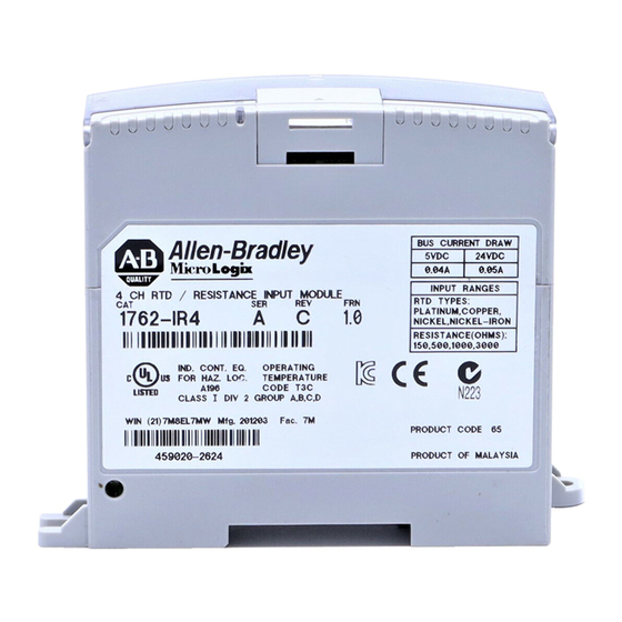
Rtd/resistance input module
Hide thumbs Also See for MicroLogix 1200:
Table of Contents

Advertisement

MicroLogix™ 1200
RTD/Resistance
Input Module
(Catalog Number 1762-IR4)
User Manual

Advertisement

Table of Contents
loading
Need help?

Need help?

Do you have a question about the MicroLogix 1200 and is the answer not in the manual?

Questions and answers

Summary of Contents for Allen-Bradley MicroLogix 1200

  • Page 1 MicroLogix™ 1200 RTD/Resistance Input Module (Catalog Number 1762-IR4) User Manual...
  • Page 2 Identifies information about practices or ATTENTION circumstances that can lead to personal injury or death, property damage, or economic loss. Identifies information that is critical for successful IMPORTANT application and understanding of the product. Allen-Bradley, MicroLogix, RSLogix, and RSLinx are trademarks of Rockwell Automation.
  • Page 3: Table Of Contents

    Table of Contents Preface Who Should Use This Manual ..... . P-1 How to Use This Manual ......P-1 Manual Contents .
  • Page 4 Table of Contents Chapter 3 Module Data, Status, and Channel Module Memory Map ......3-1 Input Image.
  • Page 5 Table of Contents Power-up Diagnostics ......4-3 Channel Diagnostics ......4-3 Invalid Channel Configuration Detection.
  • Page 6 Table of Contents Publication 1762-UM003A-EN-P - February 2003...
  • Page 7: Preface

    Chapter 3 Information on module diagnostics and troubleshooting Chapter 4 Specifications for the module Appendix A Information on programming the module using MicroLogix 1200 and Appendix B RSLogix 500 Information on understanding two’s complement binary numbers Appendix C Definitions of terms used in this manual...
  • Page 8: Related Documentation

    A user manual containing information on how to install, MicroLogix™ 1200 User Manual 1762-UM001 use and program your MicroLogix 1200 controller An overview of the MicroLogix 1200 System, including MicroLogix™ 1200 Technical Data 1762-TD001 1762 Expansion I/O. In-depth information on programming and using...
  • Page 9: Rockwell Automation Support

    Preface Rockwell Automation Rockwell Automation tests all of our products to ensure that they are fully operational when shipped from the manufacturing facility. Support If you are experiencing installation or startup problems, please review the troubleshooting information contained in this publication first. If you need technical assistance to get your module up and running, please contact Customer Support (see the table below);...
  • Page 10 Preface Publication 1762-UM003A-EN-P - February 2003...
  • Page 11: Overview

    Chapter Overview This chapter describes the four-channel 1762-IR4 RTD/resistance Input module and explains how the controller reads resistance temperature detector (RTD) or direct resistance-initiated analog input data from the module. Included is: • a general description of hardware features • an overview of module and system operation •...
  • Page 12: Rtd Compatibility

    Overview The following data formats are supported by the module.: • raw/proportional • engineering units x 1 • engineering units x 10 • scaled-for-PID • percent full scale Available filter frequencies are: • 10 Hz • 50 Hz • 60 Hz •...
  • Page 13 Overview Table 1.1 RTD Specifications Temperature Range Using Temperature Range Using Maximum Maximum RTD Type 0.5 mA Excitation 1.0 mA Excitation Scaled Scaled Resolution Repeatability Copper 426 10Ω Not allowed -100 to 260°C (-148 to 500°F) 0.1°C (0.1°F) ±0.2°C (±0.4°F) 120Ω...
  • Page 14 Overview The tables below provide specifications for RTD accuracy and temperature drift. Table 1.2 RTD Accuracy and Temperature Drift RTD Type Maximum Scaled Accuracy Maximum Scaled Accuracy Maximum Temperature Drift (25°C with Calibration) (0 to 55°C with Calibration) (from 25°C without Calibration) Copper 426 10Ω...
  • Page 15: Resistance Device Compatibility

    Overview Resistance Device Compatibility The following table lists the specifications for the resistance devices that you can use with the module. Table 1.3 Resistance Device Specifications Resistance Resistance Range Resistance Range Temperature Drift Resolution Repeatability Accuracy Device (0.5 mA Excitation) (1.0 mA Excitation) Type 150Ω...
  • Page 16: Hardware Features

    Overview Hardware Features The RTD/resistance module provides connections for four 3-wire inputs for any combination of RTD and resistance input devices. Channels are wired as differential inputs. The illustration below shows the hardware features of the module. Item Description upper panel mounting tab lower panel mounting tab power diagnostic LED module door with terminal identification label...
  • Page 17: System Overview

    Overview System Overview The modules communicate to the local controller or communication adapter through the 1762 bus interface. The modules also receive 5 and 24V dc power through the bus interface. System Operation At power-up, the module performs a check of its internal circuits, memory, and basic functions.
  • Page 18: Module Operation

    Overview Module Operation As shown in the block diagram below, each input channel of the module consists of an RTD/resistance connection that accepts excitation current; a sense connection that detects lead wire resistance; and a return connection. The signals are multiplexed to an A/D converter that reads the RTD or resistance value and the lead wire resistance.
  • Page 19: Installation And Wiring

    Chapter Installation and Wiring This chapter tells you how to: • determine the power requirements for the modules • avoid electrostatic damage • install the module • wire the module’s terminal block • wire input devices Compliance to European This product is approved for installation within the European Union and EEA regions.
  • Page 20: Power Requirements

    Installation and Wiring For specific information required by EN61131-2, see the appropriate sections in this publication, as well as the following Allen-Bradley publications: • Industrial Automation, Wiring and Grounding Guidelines for Noise Immunity, publication 1770-4.1 • Automation Systems Catalog, publication B113...
  • Page 21: Hazardous Location Considerations

    Installation and Wiring Hazardous Location Considerations This equipment is suitable for use in Class I, Division 2, Groups A, B, C, D or non-hazardous locations only. The following WARNING statement applies to use in hazardous locations. EXPLOSION HAZARD WARNING • Substitution of components may impair suitability for Class I, Division 2.
  • Page 22: Remove Power

    Installation and Wiring Remove Power Remove power before removing or inserting this ATTENTION module. When you remove or insert a module with power applied, an electrical arc may occur. An electrical arc can cause personal injury or property damage by: •...
  • Page 23: Mounting

    Installation and Wiring Mounting Do not remove protective debris strip until after the ATTENTION module and all other equipment near the module is mounted and wiring is complete. Once wiring is complete and the module is free of debris, carefully remove the protective debris strip.
  • Page 24: Din Rail Mounting

    Press the DIN rail mounting area of the module against the DIN rail. The latch will momentarily open and lock into place. Use DIN rail end anchors (Allen-Bradley part number 1492-EA35 or 1492-EAH35) for environments with vibration or shock concerns.
  • Page 25: System Assembly

    Installation and Wiring For more than 2 modules: (number of modules - 1) x 40.4 mm (1.59 in.) 40.4 14.5 (1.59) (0.57) (3.94) (3.54) NOTE: Hole spacing tolerance: ±0.4 mm (0.016 in.). 40.4 (1.59) System Assembly The expansion I/O module is attached to the controller or another I/O module by means of a ribbon cable after mounting as shown below.
  • Page 26: Field Wiring Connections

    Installation and Wiring Field Wiring Connections System Wiring Guidelines Consider the following when wiring your system: General • This product is intended to be mounted to a well-grounded mounting surface such as a metal panel. Additional grounding connections from the module’s mounting tabs or DIN rail (if used) are not required unless the mounting surface cannot be grounded.
  • Page 27: Rtd Wiring Considerations

    • If noise persists for a device, try grounding the opposite end of the cable. (You can only ground one end at a time.) • Refer to Industrial Automation Wiring and Grounding Guidelines, Allen-Bradley publication 1770-4.1, for additional information. RTD Wiring Considerations...
  • Page 28: Wiring The Finger-Safe Terminal Block

    2-10 Installation and Wiring Wiring the Finger-Safe Terminal Block Be careful when stripping wires. Wire fragments that ATTENTION fall into a module could cause damage when power is applied. Once wiring is complete, ensure the module is free of all metal fragments. When wiring the terminal block, keep the finger-safe cover in place.
  • Page 29: Wire Size And Terminal Screw Torque

    Installation and Wiring 2-11 Wire Size and Terminal Screw Torque Each terminal accepts up to two wires with the following restrictions: Wire Type Wire Size Terminal Screw Torque Solid Cu-90°C (194°F) #14 to #22 AWG 0.904 Nm (8 in-lbs) Stranded Cu-90°C (194°F) #16 to #22 AWG 0.904 Nm (8 in-lbs)
  • Page 30: Wiring Rtds

    2-12 Installation and Wiring To wire your module follow these steps: 1. At each end of the cable, strip some casing to expose the individual wires. 2. Trim the signal wires to 2-inch (5 cm) lengths. Strip about 3/16 inch (5 mm) of insulation away to expose the end of the wire. Be careful when stripping wires.
  • Page 31 Installation and Wiring 2-13 2-Wire RTD Configuration Cable Shield (to Ground) RTD EXC RTD EXC EXC 2 Return Return SENSE 2 RTN 2 Belden 9501 Shielded Cable Using 2-wire configurations does not permit the IMPORTANT module to compensate for resistance error due to lead wire length.
  • Page 32: Wiring Resistance Devices (Potentiometers)

    2-14 Installation and Wiring 4-Wire RTD Configuration Cable Shield (to Ground) RTD EXC RTD EXC EXC 2 Sense Sense SENSE 2 Return Return RTN 2 Belden 83503 or 9533 Shielded Cable Leave one sensor wire open. Wiring Resistance Devices (Potentiometers) Potentiometer wiring requires the same type of cable as that for the RTDs described on page 2-9.
  • Page 33 Installation and Wiring 2-15 Using 2-wire configurations does not permit the IMPORTANT module to compensate for resistance error due to lead wire length. The resulting analog data includes the effect of this uncompensated lead wire resistance. The module continues to place the uncompensated analog data in the input data file, but the open-circuit status bit (OCx) is set in word 4 of the input data file for any enabled channel using a 2-wire configuration.
  • Page 34 2-16 Installation and Wiring Publication 1762-UM003A-EN-P - February 2003...
  • Page 35: Module Data, Status, And Channel Configuration

    Chapter Module Data, Status, and Channel Configuration After installing the 1762-IR4 RTD/resistance input module, you must configure it for operation, usually using the programming software compatible with the controller (for example, RSLogix 500™). Once configuration is complete and reflected in ladder logic, you will need to get the module up and running and then verify its operation.
  • Page 36: Input Image

    Six words of the processor input image table are reserved for the module’s image data. You can access the information in the input Data image file using the programming software configuration screen. For more information on configuration using MicroLogix 1200 and RSLogix 500, see Appendix B. Publication 1762-UM003A-EN-P - February 2003...
  • Page 37: Input Data File

    Module Data, Status, and Channel Configuration Input Data File The input data table allows you to access RTD input module read data for use in the control program, via word and bit access. The data table structure is shown in table below. Table 3.1 Input Data Table Word/Bit RTD/Resistance Input Data Channel 0...
  • Page 38: Open-Circuit Flag Bits (Oc0 To Oc3)

    (proper configuration) but before the A/D converter can provide valid (properly configured) data to the MicroLogix 1200 controller. The following information highlights the bit operation of the Data Not Valid condition.
  • Page 39: Over-Range Flag Bits (O0 To O3)

    Module Data, Status, and Channel Configuration Over-Range Flag Bits (O0 to O3) Over-range bits for channels 0 through 3 are contained in word 5, even-numbered bits. They apply to all input types. When set (1), the over-range flag bit indicates an RTD temperature that is greater than the maximum allowed temperature or a resistance input that is greater than the maximum allowed resistance for the module.
  • Page 40: Configuration Data File

    Module Data, Status, and Channel Configuration Configuration Data File The configuration data file is shown below. Bit definitions are provided in Channel Configuration on page 3-7. Detailed definitions of each of the configuration parameters follows the table. Normal channel configuration is done using programming software.
  • Page 41: Channel Configuration

    Module Data, Status, and Channel Configuration The following table shows the basic arrangement of the configuration data file. Table 3.3 Configuration Data File Word/ 14 13 12 11 Enable/ Data Input/Sensor Temperature Open/ Cyclic Lead Excitation Filter Frequency Disable Format Type Channel 0 Units/Mode Broken...
  • Page 42 Module Data, Status, and Channel Configuration Table 3.4 Channel Configuration Bit Definitions To Select Make these bit settings 15 14 13 12 11 10 Decimals 10 Hz 60 Hz 50 Hz Filter Frequency 250Hz 500 Hz 1 kHz 1.0 mA Excitation Current 0.5 mA...
  • Page 43: Enabling Or Disabling A Channel (Bit 15)

    Module Data, Status, and Channel Configuration Enabling or Disabling a Channel (Bit 15) Bit 15 enables or disables each of the six channels individually. The module only scans those channels that are enabled. Enabling a channel forces it to be recalibrated before it measures input data. Turning a channel off results in the channel data being set to zero.
  • Page 44 3-10 Module Data, Status, and Channel Configuration Table 3.5 Data Formats for RTD Temperature Ranges for 0.5 and 1.0 mA Excitation Current Data Format RTD Input Type Engineering Units x1 Engineering Units x10 Scaled- Proportional Percent of for-PID Counts Full Scale 0.1°C 0.1°F 1.0°C...
  • Page 45 Module Data, Status, and Channel Configuration 3-11 Figure 3.1 Linear Relationship Between Temperature and Proportional Counts Counts + 32,767 ±200 ˚C °C 850 ˚C -32,768 The value +32767 corresponds to the highest value for the device. For example, if a 100Ω platinum 385 RTD is selected, the lowest temperature of -200°...
  • Page 46 3-12 Module Data, Status, and Channel Configuration Engineering Units x1 to Scaled-for-PID EXAMPLE • input type = 200Ω Platinum RTD • α = 0.00385°C • range = -200 to +850°C = -200°C = +850°C HIGH • desired channel temperature = 344°C (engineering units) Scaled-for-PID Equivalent = 16383 x [(desired ch.
  • Page 47 Module Data, Status, and Channel Configuration 3-13 Engineering Units x 1 Data Format If you select engineering units x 1 as the data format for an RTD input, the module scales input data to the actual temperature values for the selected RTD type per RTD standard.
  • Page 48: Selecting Input/Sensor Type (Bits 8 To 11)

    The amount over and under user range (full-scale range -410 to +16793) is also included in the signed integer provided to the controller. Allen-Bradley controllers, such as the MicroLogix 1500, use this range in their PID equations. See Determining Effective Resolution and Range on page 3-20.
  • Page 49: Selecting Temperature Units/Mode (Bit 7)

    Module Data, Status, and Channel Configuration 3-15 Selecting Temperature Units/Mode (Bit 7) The module supports two different linearized, scaled temperature ranges for RTDs, degrees Celsius (°C) and degrees Fahrenheit (°F). You can select the type that is appropriate for your application by setting bit 7 in the channel configuration word.
  • Page 50: Selecting Cyclic Lead Compensation (Bit 4)

    3-16 Module Data, Status, and Channel Configuration Selecting Cyclic Lead Compensation (Bit 4) For each channel, the module measures lead resistance in one of two ways. Set bit 4 to 0 to enable measurement and compensation of lead resistance every five minutes. One channel is measured per module update to limit the impact to channel throughput.
  • Page 51 Module Data, Status, and Channel Configuration 3-17 The choice that you make for filter frequency will affect: • noise rejection characteristics for module input • channel step response • channel cutoff frequency • module autocalibration • effective resolution • module update time Effects of Filter Frequency on Noise Rejection The filter frequency that you choose for a channel determines the amount of noise rejection for the inputs.
  • Page 52 3-18 Module Data, Status, and Channel Configuration the channel filter. The channel step response is calculated by a settling time of 3 x (1 / filter frequency). Table 3.7 Filter Frequency vs. Channel Step Response Filter Frequency Step Response Filter Frequency Step Response 10 Hz 300 ms...
  • Page 53 Module Data, Status, and Channel Configuration 3-19 Frequency Response Graphs 10 Hz Input Filter Frequency 50 Hz Input Filter Frequency –3 dB –3 dB –20 –20 –40 –40 –60 –60 –80 –80 -100 -100 -120 -120 -140 -140 -160 -160 -180 -180 - 200...
  • Page 54: Selecting Enable/Disable Cyclic Autocalibration (Word 4, Bit 0)

    3-20 Module Data, Status, and Channel Configuration Selecting Enable/Disable Cyclic Autocalibration (Word 4, Bit 0) Configuration word 4, bit 0 allows you to configure the module to perform an autocalibration cycle of all enabled channels once every 5 minutes. Cyclic calibration functions to reduce offset and gain drift errors due to temperature changes within the module.
  • Page 55 Module Data, Status, and Channel Configuration 3-21 Table 3.9 Effective Resolution and Range for 10 Hz Filter Frequency Raw/Proportional Data Engineering Units x 1 Engineering Units x 10 Scaled for PID Over Full Percent of Full Scale Over Full Input Range Over Full Range Over Full Range Range...
  • Page 56 3-22 Module Data, Status, and Channel Configuration Table 3.10 Effective Resolution and Range for 50-60 Hz Filter Frequency Input Raw/Proportional Data Engineering Units x 1 Engineering Units x 10 Scaled for PID Over Full Percent of Full Scale Type Over Full Range Over Full Input Range Over Full Range Range...
  • Page 57 Module Data, Status, and Channel Configuration 3-23 Table 3.11 Effective Resolution and Range for 250 Hz Filter Frequency Input Raw/Proportional Data Engineering Units x 1 Engineering Units x Scaled for PID Over Full Percent of Full Scale Type Over Full Input Range Over Full Range 10 Over Full Range Range...
  • Page 58 3-24 Module Data, Status, and Channel Configuration Table 3.12 Effective Resolution and Range for 500 Hz Filter Frequency Raw/Proportional Data Engineering Units x 1 Engineering Units x 10 Scaled for PID Over Full Percent of Full Scale Over Full Input Range Over Full Range Over Full Range Range...
  • Page 59 Module Data, Status, and Channel Configuration 3-25 Table 3.13 Effective Resolution and Range for 1 kHz Filter Frequency Input Raw/Proportional Data Engineering Units x 1 Over Engineering Units x 10 Scaled for PID Over Full Percent of Full Scale Type Over Full Input Range Full Range Over Full Range...
  • Page 60 3-26 Module Data, Status, and Channel Configuration The table below identifies the number of significant bits used to represent the input data for each available filter frequency. The number of significant bits is defined as the number of bits that will have little or no jitter due to noise, and is used in defining the effective resolution.
  • Page 61: Determining Module Update Time

    Module Data, Status, and Channel Configuration 3-27 Determining Module The module update time is defined as the time required for the module to sample and convert the input signals of all enabled input Update Time channels and provide the resulting data values to the processor. The module sequentially samples the channels in a continuous loop as shown below.
  • Page 62: Effects Of Autocalibration On Module Update Time

    3-28 Module Data, Status, and Channel Configuration Module update time can be calculated by obtaining the sum of all enabled channel update times. Channel update times include channel scan time, channel switching time, and reconfiguration time. 1. Module Update Time with all channels enabled EXAMPLE and configured with 10 Hz filter = 4 x 303 ms = 1212 ms...
  • Page 63 Module Data, Status, and Channel Configuration 3-29 Calculating Module Update Time with Autocalibration Enabled The following example illustrates how to determine module update time with autocalibration enabled. Two Channels Enabled with Cyclic Calibration EXAMPLE Channel 0 Input: 100Ω Platinum 385, 1.0 mA source with 60 Hz Filter zews Channel 1 Input: 100Ω...
  • Page 64: Effects Of Cyclic Lead Wire Compensation On Module Update Time

    3-30 Module Data, Status, and Channel Configuration Effects of Cyclic Lead Wire Compensation on Module Update Time The 1762-IR4 module provides the option to enable lead wire compensation for each channel. This feature improves measurement accuracy for 3- and 4-wire RTDs by compensating for the resistance of the RTD lead wire.
  • Page 65: Calculating Module Update Time With Cyclic Lead Wire Compensation Enabled

    Module Data, Status, and Channel Configuration 3-31 Calculating Module Update Time with Cyclic Lead Wire Compensation Enabled The following example illustrates how to determine module update time with cyclic lead wire compensation enabled. Two Channels Configured with Cyclic Lead Wire Compensation Enabled EXAMPLE Channel 0 Input: 100Ω...
  • Page 66: Impact Of Autocalibration And Lead Wire Compensation On Module Startup

    3-32 Module Data, Status, and Channel Configuration Impact of Autocalibration and Lead Wire Compensation on Module Startup Regardless of the selection of the Enable/Disable Cyclic Calibration and Enable/Disable Cyclic Lead Calibration functions, a cycle of both of these functions occurs automatically on a mode change from Program-to-Run and on subsequent module startups/initialization for all configured channels.
  • Page 67: Effects Of Autocalibration On Accuracy

    Module Data, Status, and Channel Configuration 3-33 Effects of Autocalibration The module performs autocalibration to correct for drift errors over temperature. Autocalibration occurs immediately following on Accuracy configuration of a previously unselected channel, during power cycle of enable channels and every 5 minutes if so configured. The table below shows module accuracy with and without calibration.
  • Page 68 3-34 Module Data, Status, and Channel Configuration Publication 1762-UM003A-EN-P - February 2003...
  • Page 69: Diagnostics And Troubleshooting

    Chapter Diagnostics and Troubleshooting This chapter describes module troubleshooting, containing information on: • safety considerations when troubleshooting • module vs. channel operation • the module’s diagnostic features • critical vs. non-critical errors • module condition data • contacting Rockwell Automation for assistance Safety Considerations Safety considerations are an important element of proper troubleshooting procedures.
  • Page 70: Activating Devices When Troubleshooting

    Module-level operations include functions such Channel Operation as power-up, configuration, and communication with the MicroLogix 1200 controller. Channel-level operations describe channel-related functions, such as data conversion and over- or under-range detection. Publication 1762-UM003A-EN-P - February 2003...
  • Page 71: Power-Up Diagnostics

    Diagnostics and Troubleshooting Internal diagnostics are performed at both levels of operation. When detected, module error conditions are immediately indicated by the module status LED. Both module hardware and channel configuration error conditions are reported to the controller. Channel over-range or under-range conditions are reported in the module’s input data table.
  • Page 72: Open-Wire Or Short-Circuit Detection

    Diagnostics and Troubleshooting Possible causes for an out-of-range condition include: • The temperature is too hot or too cold for the RTD being used. • The wrong RTD is being used for the input type selected, or for the configuration that you have programmed. •...
  • Page 73: Module Error Definition Table

    Diagnostics and Troubleshooting Module Error Definition Module errors are expressed in two fields as four-digit Hex format with the most significant digit as irrelevant (“don’t care”). The two Table fields are “Module Error” and “Extended Error Information”. The structure of the module error data is shown below. Table 4.1 Module Error Table “Don’t Care”...
  • Page 74: Extended Error Information Field

    Diagnostics and Troubleshooting Extended Error Information Field Check the extended error information field when a non-zero value is present in the module error field. Depending upon the value in the module error field, the extended error information field can contain error codes that are module-specific or common to all 1762 analog modules.
  • Page 75: Error Codes

    Diagnostics and Troubleshooting Error Codes The table below explains the extended error code. Table 4.3 Extended Error Codes Error Type Module Extended Error Error Description Error Information Equivalent Code Code Binary Binary No Error X000 0 0000 0000 No Error General Common X200 0 0000 0000...
  • Page 76: Module Inhibit Function

    Module Inhibit Function Whenever the 1762-IR4 module is inhibited, the module continues to provide information about changes at its inputs to the MicroLogix 1200 controller. Contacting Rockwell If you need to contact Rockwell Automation for assistance, please have the following information available when you call: Automation •...
  • Page 77: General Specifications

    Appendix Specifications General Specifications Specification Value Dimensions 90 mm (height) x 87 mm (depth) x 40 mm (width) height including mounting tabs is 110 mm 3.54 in. (height) x 3.43 in (depth) x 1.58 in (width) height including mounting tabs is 4.33 in. Approximate Shipping Weight 260g (0.57 lbs.) (with carton)
  • Page 78: Input Specifications

    Specifications Input Specifications Specification 1762-IR4 • 100Ω Platinum 385 Input Types • 200Ω Platinum 385 • 500Ω Platinum 385 • 1000Ω Platinum 385 • 100Ω Platinum 3916 • 200Ω Platinum 3916 • 500Ω Platinum 3916 • 1000Ω Platinum 3916 • 10Ω Copper 426 •...
  • Page 79 Specifications Specification 1762-IR4 Accuracy Drift at 0 to 55° C (+32 to ±0.026°C/°C (0.026°F/°F) for Pt 385 ±0.007Ω/°C (0.012Ω/°F) for 150Ω range +131°F) ±0.023°C/°C (0.023°F/°F) for Pt 3916 ±0.023Ω/°C (0.041Ω/°F) for 500Ω range ±0.012°C/°C (0.012°F/°F) for Ni ±0.043Ω/°C (0.077Ω/°F) for 1000Ω range ±0.015°C/°C (0.015°F/°F) for NiFe ±0.072Ω/°C (0.130Ω/°F) for 3000Ω...
  • Page 80: Cable Specifications

    Specifications Cable Specifications Description Belden #9501 Belden #9533 Belden #83503 When used? For 2-wire RTDs and For 3-wire RTDs and potentiometers. For 3-wire RTDs and potentiometers. potentiometers. Short runs less than 100 feet and normal Long runs greater than 100 feet or high humidity levels.
  • Page 81 Appendix Two’s Complement Binary Numbers The processor memory stores 16-bit binary numbers. Two’s complement binary is used when performing mathematical calculations internal to the processor. Analog input values from the analog modules are returned to the processor in 16-bit two’s complement binary format.
  • Page 82 Two’s Complement Binary Numbers Negative Decimal Values In two’s complement notation, the far left position is always 1 for negative values. The equivalent decimal value of the binary number is obtained by subtracting the value of the far left position, 32768, from the sum of the values of the other positions.
  • Page 83: Module Addressing

    Appendix Configuring the 1762-IR4 Module Using RSLogix 500 This appendix examines the 1762-IR4 module’s addressing scheme and describes module configuration using RSLogix 500. Module Addressing The following memory map shows the input image table for the module. Detailed information on the image table is located in Chapter 3.
  • Page 84: Configuration Using Rslogix 500 Version 5.50 Or Higher

    RSLogix 500 Version 5.50 or software. It assumes that your module is installed as expansion I/O in Higher a MicroLogix 1200 system, that RSLinx™ is properly configured, and that a communications link has been established between the MicroLogix processor and RSLogix 500.
  • Page 85 Configuring the 1762-IR4 Module Using RSLogix 500 While offline, double-click on the IO Configuration icon under the controller folder and the following IO Configuration screen appears. This screen allows you to manually enter expansion modules into expansion slots, or to automatically read the configuration of the controller.
  • Page 86 Configuring the 1762-IR4 Module Using RSLogix 500 The 1762-IR4 module is installed in slot 1. To configure the module, double-click on the module/slot. The general configuration screen appears. Configuration options for channels 0 to 2 are located on a separate tab from channel 3, as shown below.
  • Page 87 Configuring the 1762-IR4 Module Using RSLogix 500 Use the Calibration tab (Cal) to disable cyclic calibration. For more information on the autocalibration feature, see Selecting Enable/Disable Cyclic Autocalibration (Word 4, Bit 0) on page 3-20. Generic Extra Data Configuration This tab re-displays the configuration information entered on the Analog Input Configuration screen in a raw data format.
  • Page 88: Configuration Using Rslogix 500 Version 5.2 Or Lower

    Configuring the 1762-IR4 Module Using RSLogix 500 Configuration Using If you do not have version 5.5 or higher of RSLogix 500, you can still configure your module, using the Generic Extra Data Configuration RSLogix 500 Version 5.2 or dialog. Lower To configure the 1762-IR4, select "Other -- Requires I/O Card Type ID"...
  • Page 89 Configuring the 1762-IR4 Module Using RSLogix 500 Enter -15597 into the Generic Extra Data Config Tab as shown below. Publication 1762-UM003A-EN-P - February 2003...
  • Page 90 Configuring the 1762-IR4 Module Using RSLogix 500 Publication 1762-UM003A-EN-P - February 2003...
  • Page 91 Glossary The following terms and abbreviations are used throughout this manual. For definitions of terms not listed here refer to Allen-Bradley’s Industrial Automation Glossary, Publication AG-7.1. A/D Converter Refers to the analog to digital converter inherent to the module. The converter produces a digital value whose magnitude is proportional to the magnitude of an analog input signal.
  • Page 92 Glossary common mode voltage range The largest voltage difference allowed between either the positive or negative terminal and analog common during normal differential operation. configuration word Word containing the channel configuration information needed by the module to configure and operate each channel. cut-off frequency The frequency at which the input signal is attenuated 3 dB by a digital filter.
  • Page 93 Glossary filter A device that passes a signal or range of signals and eliminates all others. filter frequency The user-selectable frequency for a digital filter. full-scale The magnitude of input over which normal operation is permitted. full-scale range The difference between the maximum and minimum specified analog input values for a device.
  • Page 94 Glossary full-scale input. See the variation from the straight line due to linearity error (exaggerated) in the example below. Actual Transfer Function Ideal Transfer Least significant bit. The LSB represents the smallest value within a string of bits. For analog modules, 16-bit, two’s complement binary codes are used in the I/O image.
  • Page 95 Glossary overall accuracy The worst-case deviation of the digital representation of the input signal from the ideal over the full input range is the overall accuracy. Overall accuracy is expressed in percent of full scale. repeatability The closeness of agreement among repeated measurements of the same variable under the same conditions.
  • Page 96 Glossary Publication 1762-UM003A-EN-P - February 2003...
  • Page 97 Index common mode rejection definition G-1 common mode rejection ratio definition G-1 definition G-1 A/D converter 1-8, 3-9 common mode voltage abbreviations G-1 definition G-1 accuracy common mode voltage range autocalibration 3-33 definition G-2 module 3-33 configuration 3-1 overall 1-4 default 3-9 resistance device 1-5 periodic calibration 3-20...
  • Page 98 Index effective resolution gain drift 1 kHz 3-25 definition G-3 10 Hz 3-21 grounding 2-8 250 Hz 3-23 500 Hz 3-24 50-60 Hz 3-22 hardware errors 4-6 definition G-2 number of significant bits 3-26 heat considerations 2-4 electrical noise 2-4 EMC Directive 2-1 engineering units x 1 3-13 input data scaling...
  • Page 99 Index multiplexer register definition G-4 configuration 3-1 multiplexing 1-8 data, status 3-1 resistance device accuracy 1-5 input type 1-5 negative decimal values C-2 range 1-5 noise 3-17 repeatability 1-5 noise rejection 3-17 resolution 1-5 specifications 1-5 normal mode rejection temperature drift 1-5 definition G-4 resolution number of significant bits 3-26...
  • Page 100 Index terminal block 2-10 terminal screw torque 2-11 wiring 2-1 wire size 2-11 input devices 2-11 routing considerations 2-4 Publication 1762-UM003A-EN-P - February 2003...
  • Page 104 Publication 1762-UM003A-EN-P - February 2003 Copyright © 2003 Rockwell Automation, Inc. All rights reserved. Printed in the U.S.A.

This manual is also suitable for:

1762-ir4

Table of Contents