
Related Manuals for Allen-Bradley 1794-IRT8


Summary of Contents for Allen-Bradley 1794-IRT8
- Page 1 Allen-Bradley User Thermocouple/ RTD/Millivolt Manual Input Module (Cat. No. 1794-IRT8) Allen-Bradley PLCs...
- Page 2 DeviceNet, DeviceNetManager, and RediSTATION are trademarks of Allen-Bradley Company, Inc. PLC, PLC-2, PLC-3, and PLC-5 are registered trademarks of Allen-Bradley Company, Inc. Windows is a trademark of Microsoft. Microsoft is a registered trademark of Microsoft IBM is a registered trademark of International Business Machines, Incorporated.
- Page 3 Allen-Bradley PLCs Publication 1794-6.5.12 - November 1997...
- Page 4 Audience We assume that you have previously used an Allen-Bradley programmable controller, that you are familiar with its features, and that you are familiar with the terminology we use. If not, read the user manual for your processor before reading this manual.
- Page 5 1794-IE8 24V dc Selectable Analog 8 Input Module 1794-5.6 1794-OE4 24V dc Selectable Analog 4 Output Module 1794-5.5 1794-6.5.2 1794-IE4XOE2 24V dc 4 Input/2 Output Analog Module 1794-5.15 Table continued on next page Allen-Bradley PLCs Publication 1794-6.5.12 - November 1997...
- Page 6 1794-5.39 1794-IR8 24V dc 8 RTD Input Analog Module 1794-5.22 1794-6.5.4 1794-IT8 24V dc 8 Thermocouple Input Module 1794-5.21 1794-6.5.7 1794-IRT8 24V dc 8 Thermocouple/RTD Input Module 1794-5.50 1794-6.5.12 1794-IJ2 24V dc 2 Frequency Input Module 1794-5.49 1794-6.5.11 1794-IA8 120V ac 8 Input Module 1794-5.9...
- Page 7 Using This Manual Allen-Bradley PLCs Publication 1794-6.5.12 - November 1997...
-
Page 8: Table Of Contents
Terminal Base Units ........2-9 Wiring connections for the 1794-IRT8 TC/RTD/mV Input Module . - Page 9 Bit/Word Descriptions for the Thermocouple/RTD/mV Input Module (1794-IRT8)......5-5 Defaults ..........5-11 Chapter Summary .
-
Page 10: What The Thermocouple/Rtd/Mv Input Module Does
Module features ........1-3 What the The 1794-IRT8 module accepts up to 8 thermocouple or RTD inputs. The Thermocouple/RTD/mV inputs are nonisolated and are selected with analog multiplexers which have a common-mode input range of ±4 volts. -
Page 11: Typical Communication Between An Adapter And A Module
Typical Communication Between an Adapter and a Module The adapter transfers your configuration data External devices transmit to the module using a BTW. analog signals to the module. Flexbus Allen-Bradley Allen-Bradley 1794-IRT8 TC RTD INPUT 8 CHANNEL 24VDC ADAPTER LOCAL POWER SUPPLY FAULT ACTIVE FAULT... -
Page 12: Features Of Your Module
The module label identifies the keyswitch position, wiring and module type. A removable label provides space for writing individual designations per your application. Indicators are provided to identify input fault conditions, and to show when power is applied to the module. 1794-IRT8 Module Type Removable Label Allen-Bradley... - Page 13 Overview of FLEX I/O and Your Thermocouple/RTD/mV Input Module Allen-Bradley PLCs Publication 1794-6.5.12 - November 1997...
-
Page 14: What This Chapter Contains
Chapter How to Install Your Thermocouple/RTD/mV Input Module What This Chapter In this chapter, we tell you: Contains For information on See page Before You Install Your Module ......2-1 European Union Directives . -
Page 15: Low Voltage Directive
EN 61131-2 Programmable Controllers, Part 2 – Equipment Requirements and Tests. For specific information required by EN 61131-2, see the appropriate sections in this publication, as well as the following Allen-Bradley publications: • Industrial Automation Wiring and Grounding Guidelines For Noise Immunity, publication 1770-4.1... -
Page 16: Wiring The Terminal Base Units (1794-Tb3G Shown)
How to Install Your Thermocouple/RTD/mV Input Module Methods of wiring the terminal base units are shown in the illustration below. Wiring the Terminal Base Units (1794-TB3G shown) ATTENTION: Do not daisy chain power or ground from the terminal base unit to any ac or dc digital module terminal base unit. -
Page 17: Installing The Module
Pro- ceed as follows: Position terminal base at a slight angle and hooked over the top of the DIN rail. Allen-Bradley PLCs Publication 1794-6.5.12 - November 1997... - Page 18 How to Install Your Thermocouple/RTD/mV Input Module Slide the terminal base unit over tight against the adapter. Make sure the hook on the terminal base slides under the edge of the adapter and the flexbus connector is fully retracted. Press down on the terminal base unit to lock the terminal base on the DIN rail.
-
Page 19: Panel/Wall Mounting
1 - Mounting Plate for Adapter 2 - 18 #6 self-tapping screws (2 for the adapter, and 2 each for up to 8 modules) Adapter Module (not included) Terminal Base Unit (not included) Allen-Bradley PLCs Publication 1794-6.5.12 - November 1997... - Page 20 How to Install Your Thermocouple/RTD/mV Input Module To install the mounting plate on a wall or panel: 1. Lay out the required points on the wall/panel as shown in the drilling dimension drawing. Drilling Dimensions for Panel/Wall Mounting of FLEX I/O (58.5) (35.5) (58.5)
-
Page 21: Mounting The Thermocouple/Rtd/Mv Module On The Terminal Base Unit
Worn contacts may create electrical resistance. 4. Position the module (4) with its alignment bar (5) aligned with the groove (6) on the terminal base. Allen-Bradley PLCs Publication 1794-6.5.12 - November 1997... -
Page 22: Connecting Wiring For The Tc/Rtd/Mv Module
TC/RTD/mV Module on which the module mounts. Compatible terminal base units are: Module 1794-TB3G 1794-TB3GS 1794-IRT8 1794-TB3G 1794-TB3GS 9 10 11 12 13 14 15 18 19 20 21 22 23 24 25 26 27 28 29 30 31 32... - Page 23 Channel 1 Channel 2 Channel 3 Channel 4 Channel 5 Channel 6 Channel 7 Chassis Gnd Chassis Gnd 6 Chassis Ground +V COM for Shields 24V dc 24V dc Supply In Supply Out Allen-Bradley PLCs Publication 1794-6.5.12 - November 1997...
-
Page 24: Input Module
How to Install Your Thermocouple/RTD/mV Input Module 2-11 Wiring connections for the 1794-IRT8 TC/RTD/mV Input Module Connect the following: 2-wire Type of Input – Shield RTD – 2-wire 3-wire RTD – 3-wire RTD – 4-wire Thermocouple Millivolt 1 Terminals 37, 38 and 39 and 46, 47 and 48 are for cold junction compensation (with 38... -
Page 25: Example Of 2-, 3- And 4-Wire Rtd And Thermocouple Wiring To A 1794-Tb3G Terminal Base Unit
1794-TB3G Terminal Base Unit Thermocouple Channel 4 2-Wire RTD Channel 1 3-Wire RTD Channel 2 4-Wire RTD Channel 3 0 -15 16-33 34-51 1794-TB3G Attention: Keep exposed area of inner conductor as short as possible. Allen-Bradley PLCs Publication 1794-6.5.12 - November 1997... -
Page 26: Module Indicators
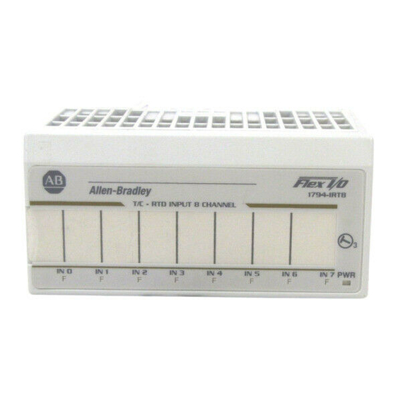
Module Indicators The Thermocouple/RTD/mV module has one status indicator (PWR) that is on when power is applied to the module and one fault indicator (F) for each input. Allen-Bradley 1794-IRT8 TC RTD INPUT 8 CHANNEL IN 0 IN 1 IN 2... - Page 27 2-14 How to Install Your Thermocouple/RTD/mV Input Module Allen-Bradley PLCs Publication 1794-6.5.12 - November 1997...
-
Page 28: What This Chapter Contains
Chapter Programming Your Thermocouple/RTD Input Module What This Chapter To initiate communication between the Thermocouple/RTD input module Contains and your PLC processor, you must enter block transfer instructions into your ladder logic program. Use this chapter to enter the necessary block transfer instructions into your ladder logic program. -
Page 29: Plc-2 Family Processor
The same block transfer control file is used for both the read and write instructions for your module. A different block transfer control file is required for every module. Allen-Bradley PLCs Publication 1794-6.5.12 - November 1997... -
Page 30: Plc-5 Family Processor
Programming Your Thermocouple/RTD Input Module PLC-3 Processor Rung M:0 Program Example The IRT8 module is located in rack 3, I/O group 2, slot 1. The control file is a 10 word file starting at B17:0 that is shared by the BTR/BTW. The data obtained by the PLC3 processor is placed in memory starting at location N18:101, and with the default length of 0, is 11 words long. -
Page 31: Plc-5/250 Processor
A different block transfer control file is used for the read and write instructions for your module. A different block transfer control file is required for every module. Allen-Bradley PLCs Publication 1794-6.5.12 - November 1997... -
Page 32: Chapter Summary
Programming Your Thermocouple/RTD Input Module PLC-5/250 Processor Rung 1STEPO:1 Program Example The IRT8 module is located in rack 14, I/O group 1, slot 0. The data obtained by the PLC-5/250 processor from the IRT8 module is placed in the data table starting at 2BTD5:101, and with the default length of 0, is 11 words long. - Page 33 Programming Your Thermocouple/RTD Input Module Allen-Bradley PLCs Publication 1794-6.5.12 - November 1997...
-
Page 34: Configuring Your Thermocouple/Rtd/Mv Input Module
Mapping Data for the Module ......4-3 TC/RTD Input Module (1794-IRT8) Image Table Mapping..4-3 Block Transfer Read Word Assignments . -
Page 35: Sensor Types
–50 to 1768°C (–58 to 3214°F) –50 to 1768°C (–58 to 3214°F) –270 to 400°C (–454 to 752°F) You select individual channel ranges using write word 1 of the block transfer write instruction. Allen-Bradley PLCs Publication 1794-6.5.12 - November 1997... -
Page 36: Reading Data From Your Module
TC/RTD input module. The module uses up to 11 words of input data and up to 4 words of output Module data. Each word is composed of 16 bits. Thermocouple/RTD Input Module (1794-IRT8) Image Table Mapping Module Image Input Data Channel 0... -
Page 37: Bit/Word Descriptions For The Thermocouple/Rtd Input Module (1794-Irt8) Block Transfer Read Words
Rsvd Rsvd Diagnostic Status Resp EDT command response EDT response data Bit/Word Descriptions for the Thermocouple/RTD Input Module (1794-IRT8) Block Transfer Read Words Dec. Bits Word Description (Octal Bits) Read Word 0 00-15 (00-17) Channel 0 Input data Read Word 1... -
Page 38: Thermocouple/Rtd/Mv Input Module (1794-Irt8) Write Words
Writing Configuration to and Reading Status from Your Module with a Remote I/O Adapter Thermocouple/RTD/mV Input Module (1794-IRT8) Write Words Output Mapping Decimal Octal Word ⇓ Write Not used Data Format Mode Mode Reference Jct. Filter Cutoff Ch 0-3 Ch 4-7... - Page 39 200 ohm Pt α = 0.003916 U.S. (–200 to +400°C) 100 ohm Nickel (–60 to +250°C) 200 ohm Nickel (–60 to +200°C) 120 ohm Nickel (–80 to +320°C) 10 ohm Copper (–200 to +260°C) 1001 through 1111 not used Allen-Bradley PLCs Publication 1794-6.5.12 - November 1997...
- Page 40 Writing Configuration to and Reading Status from Your Module with a Remote I/O Adapter Dec. Bits Word Description (Octal Bits) Write Word 1 Bits 00-03 Thermocouple Type cont. Bit 03 02 01 00 Sensor type for channels 0 through 3 mV (default) 300 to 1800°C (572 to 3272°F)
- Page 41 Internal compensation – uses the value selected for reference junction No compensation (Data is referenced to 0°C.) Differential measurement between 2 channels 2-wire RTD no compensation 2-wire RTD with loop resistance compensation 3-wire RTD 4-wire RTD Allen-Bradley PLCs Publication 1794-6.5.12 - November 1997...
-
Page 42: Chapter Summary
Writing Configuration to and Reading Status from Your Module with a Remote I/O Adapter Dec. Bits Word Description (Octal Bits) word 1 cont. Bits 14-15 Input Type Select (16-17) Bit 15 14 Input type selection for channels 4-7 Thermocouple Not used Write Word 2 00-15 (00-17) RTD loop resistance offset select bits –... - Page 43 4-10 Writing Configuration to and Reading Status from Your Module with a Remote I/O Adapter Allen-Bradley PLCs Publication 1794-6.5.12 - November 1997...
-
Page 44: Chapter Objectives
Chapter How Communication Takes Place and I/O Image Table Mapping with the DeviceNet Adapter Chapter Objectives In this chapter, we tell you about: • DeviceNetManager software • I/O structure • image table mapping • factory defaults About DeviceNetManager DeviceNetManager software is a tool used to configure your FLEX I/O Software DeviceNet adapter and its related modules. -
Page 45: Adapter Input Status Word
The node address changed bit is set when the node address switch setting has been changed since power up. The new node address does not take affect until the adapter has been powered down and then powered back up. Allen-Bradley PLCs Publication 1794-6.5.12 - November 1997... -
Page 46: System Throughput
A/D output data rate, thus affecting system throughput. Mapping Data into the FLEX I/O Thermocouple/RTD input module data table mapping is shown below. Image Table Thermocouple/RTD Input Module (1794-IRT8) Image Table Mapping Module Image Input Data Channel 0 Input Data Channel 1... -
Page 47: Thermocouple/Rtd Input Module (1794-Irt8) Read Words
How Communication Takes Place and I/O Image Table Mapping with the DeviceNet Adapter Thermocouple/RTD Input Module (1794-IRT8) Read Words Decimal Octal Word ⇓ Read Channel 0 Input Data Channel 1 Input Data Channel 2 Input Data Channel 3 Input Data... -
Page 48: Input Module (1794-Irt8)
How Communication Takes Place and I/O Image Table Mapping with the DeviceNet Adapter Bit/Word Descriptions for the Thermocouple/RTD/mV Input Module (1794-IRT8) Dec. Bits Word Description (Octal Bits) Read Word 1 00-15 (00-17) Channel 0 Input data Read Word 2 00-15 (00-17) Channel 1 Input data... - Page 49 Data format – module defaults to –4000 to 10000 in millivolt mode, and 0 to 5000 in ohms mode (10-13) Data type for channels 0-7 °C °F °K –32767 to +32767 0 to 65535 0101 through 1111 not used Bits 12-15 Not used (14-17) Allen-Bradley PLCs Publication 1794-6.5.12 - November 1997...
- Page 50 How Communication Takes Place and I/O Image Table Mapping with the DeviceNet Adapter Dec. Bits Word Description (Octal Bits) Write Word 2 Bits 00-03 Sensor Type (Thermocouple or RTD) RTD Type Sensor type for channels 0 through 3 Resistance (default) 100 ohm Pt α...
- Page 51 Differential measurement between 2 channels 2-wire RTD no compensation 2-wire RTD with loop resistance compensation 3-wire RTD 4-wire RTD Bits 06-07 Input Type Select Input type selection for channels 0-3 Thermocouple Not used Allen-Bradley PLCs Publication 1794-6.5.12 - November 1997...
- Page 52 How Communication Takes Place and I/O Image Table Mapping with the DeviceNet Adapter Dec. Bits Word Description (Octal Bits) Write Word 2 Bits 08-11 Sensor Type (Thermocouple or RTD) cont. (10-13) RTD Type Sensor type for channels 4 through 7 Resistance (default) 100 ohm Pt α...
- Page 53 They are used to define offset, gain and general channel calibration. 08-14 (10-16) Extended data table command bits – These bits are written to the module during calibration. They are used to select channel calibration action. 15 (17) Reserved for factory use only. Allen-Bradley PLCs Publication 1794-6.5.12 - November 1997...
-
Page 54: Defaults
Output Description Number Default Default Default Default 1794-IRT8 8-Input Thermocouple/RTD Input Factory defaults are the values assigned by the adapter when you: • first power up the system, and • no previous stored settings have been applied. For analog modules, the defaults reflect the actual number of input words/output words. - Page 55 5-12 How Communication Takes Place and I/O Image Table Mapping with the DeviceNet Adapter Allen-Bradley PLCs Publication 1794-6.5.12 - November 1997...
-
Page 56: What This Chapter Contains
Chapter Calibrating Your Module What This Chapter Use this chapter to calibrate the thermocouple/RTD/mV input module. We tell you about: Contains For information on See page When and How to Calibrate Your TC/RTD Module ....6-1 Tools and Equipment. -
Page 57: Tools And Equipment
6. The module computes new calibration values for the inputs and returns a BTR which echoes back the message sent in the BTW word. If the calibration is cannot be completed, the module returns a fault message. Allen-Bradley PLCs Publication 1794-6.5.12 - November 1997... -
Page 58: Calibration Setups
Calibrating Your Module Calibration Setups Using Precision Resistors - for 383W and 100W calibration 9 10 12 13 Using Precision Voltage Source - for offset and gain calibration 13 14 Precision Voltage Source 1794-TB3G Connect + to terminals 2, 6, 10, 14, 19, 23, 27, and 31 Connect - to terminals 3, 7, 11, 15, 20, 21, 28 and 32 Connect one 10K ohm, 0.5% resistor across terminals 37 and 39 and another across 46 and 48. -
Page 59: Read/Write Words For Calibration
Underrange Alarm Bits (channel 0 = bit 00, etc) Flt Alm Flt Alm Flt Alm Flt Alm Flt Alm Flt Alm Flt Alm Flt Alm CJC 2 CJC 1 Diagnostic Status used EDT command response EDT response data Allen-Bradley PLCs Publication 1794-6.5.12 - November 1997... -
Page 60: Edt Calibration Command And Command Data
Calibrating Your Module EDT Calibration Command and Command Data Data Data Command Meaning Meaning (up nibble) (low nibble) Dec. (Hex) channel command General Calibration by Channel 0-15 zero offset and gain coefficients 0-15 channel internal current source and current sense resistor, with 4-wire external 383Ω... -
Page 61: Offset Calibration
3. Initiate a BTW to the module with the appropriate value in BTW word 3, bits 00-15, as shown above. 4. Monitor the block transfer read word 10 bits 00-15 for an echo of the EDT command. Allen-Bradley PLCs Publication 1794-6.5.12 - November 1997... -
Page 62: Gain Calibration
Calibrating Your Module If the BTR word reads 80FF (hex), repeat the BTW. Make sure that sufficient time is allowed for the module to respond to your request. 5. Set the precision millivolt source to the value required for a gain of 2. Repeat steps 3 and 4 for gain 2. -
Page 63: Current Source Calibration
4. Monitor the block transfer read word 10, bits 00-15 for an echo of the EDT command. If the BTR word reads 80FF (hex) (indicating a failed calibration), repeat the BTW. Make sure that sufficient time is allowed for the module to respond to your request. Allen-Bradley PLCs Publication 1794-6.5.12 - November 1997... - Page 64 Appendix Specifications Specifications – 1794-IRT8 Thermocouple/RTD/mV Input Module Number of Inputs 8 Channels (2 groups of 4) Module Location Cat. No. 1794-TB3G, -TB3GS Terminal Base Unit Nominal Ranges –40 to +100mV dc for thermocouples 0 to 500Ω for RTDs Supported Thermocouple Types Type B: 300 to 1800°C...
- Page 65 Specifications Specifications – 1794-IRT8 Thermocouple/RTD/mV Input Module System Throughput (8 channels scanned) For maximum throughput short circuit all unused channels. 4ms – millivolt 6.0ms – ohms – 2- and 4-wire RTD 10.0ms – ohms – 3-wire RTD 6.4ms – 2- and 4-wire RTD (°F) 6.8ms –...
- Page 66 Index Numerics commands EDT, 6-6 1794TB3G wiring examples, 2-12 EDT command data, 6-6 communication between module and adapter, 1-2 adapter input status word, 5-1 block transfers, 3-1 compatible terminal bases, 2-9 configurable features, 4-1 bit/word description connecting wiring, 2-9, 6-3 TC/RTD/mV analog module considerations 1794IRT8, 4-4...
- Page 67 2-6 connections, 6-3 PLC2 family processor, 3-2 methods of, 2-3 PLC3 family processor, 3-2 wiring connections, 2-9 PLC5 family processor, 3-3 1794IRT8, 2-11, 6-3 PLC5/250 processor, 3-4 preparing for calibration, 6-2 Allen-Bradley PLCs Publication 1794-6.5.12 - November 1997...
- Page 68 What is unclear? Sequence What is not in the right order? Other Comments Use back for more comments. Your Name Location/Phone Return to: Marketing Communications, Allen-Bradley Co., 1 Allen-Bradley Drive, Mayfield Hts., OH 44124-6118Phone: (216)646-3176 FAX: (216)646-4320 Publication ICCG-5.21-August1995 PN955107-82...
- Page 69 PLEASE FOLD HERE Ã NO POSTAGE NECESSARY IF MAILED IN THE UNITED STATES BUSINESS REPLY MAIL FIRST-CLASS MAIL PERMIT NO. 18235 CLEVELAND OH POSTAGE WILL BE PAID BY THE ADDRESSEE TECHNICAL COMMUNICATION 1 ALLEN BRADLEY DR MAYFIELD HEIGHTS OH 44124-9705 Allen-Bradley PLCs...
- Page 70 Support Services At Allen-Bradley, customer service means experienced representatives at Customer Support Centers in key cities throughout the world for sales service and support. Our value-added services include: Technical Support • SupportPlus programs • telephone support and 24-hour emergency hotline •...
- Page 71 Allen-Bradley PLCs Publication 1794-6.5.12 - November 1997 PN 955128-51 © 1997 Rockwell International. All Rights Reserved. Printed in USA...
Need help?
Do you have a question about the 1794-IRT8 and is the answer not in the manual?
Questions and answers