Subscribe to Our Youtube Channel
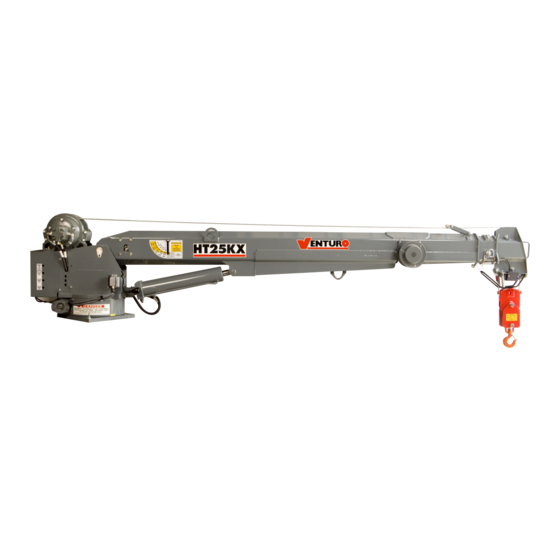
Summary of Contents for Venturo HT25KX
- Page 3 TABLE OF CONTENTS HT25KX / Std Ctrl / No Eng Ctrls (HLAAAB-00**) SECTION 100 DESCRIPTION & SPECIFICATIONS 19801 INSTALLATION DIMENSIONS 19930 BASE MOUNTING DIMENSIONS I19233 CAPACITY CHART - HT25KX I19288 SERVICE BODY REINFORCEMENT 14510 FLAT BED REINFORCEMENT SECTION 150 SAFETY 15394 VEHICLE &...
- Page 5 SECTION 100 DESCRIPTION & SPECIFICATIONS 7607100A...
- Page 11 SECTION 150 SAFETY 8604150...
- Page 12 VEHICLE & CRANE MOUNTED ELECTRICAL HAZARD SIGN APPLICATION & INFORMATION ET & HT CRANE SERIES SIGN NO. 15393A DISPLAYS THE INTERNATIONAL SYMBOL FOR ELECTRICITY AND WARNS OF DANGER FROM AN ELECTRICALLY CHARGED VEHICLE, CRANE, OR LOAD. FOUR ARE RECOMMENDED (ONE FOR EACH SIDE AND ONE FOR EACH END OF VEHICLE) TO BE APPLIED IN LOCATIONS WHICH ARE READILY VISIBLE TO GROUND PERSONNEL.
- Page 13 CRANE SAFETY AND HAZARDS HT25KX, HT40KX, HT50KX CAUTIONS 1. INSPECT VEHICLE AND CRANE, INCLUDING OPERATION, PRIOR TO USE DAILY. 2. DO NOT USE THIS EQUIPMENT EXCEPT ON SOLID, LEVEL SURFACE WITH CRANE MOUNTED ON FACTORY-RECOMMENDED TRUCK. 3. BEFORE OPERATING THE CRANE, REFER TO MAXIMUM LOAD (CAPACITY) CHART ON CRANE FOR OPERATING (LOAD) LIMITATIONS.
- Page 14 WINCH SAFETY WARNINGS DATE SECTION TITLE INSTALLATION DWG 5-26-98B C150 MFG., INC. SUPERCEDES I19217 CINCINNATI, OHIO HT CRANES 10-17-97A...
- Page 16 SECTION 200 INSTALLATION 7607200A...
- Page 17 The truck body must be reinforced and outriggers provided to withstand the combined loads resulting from lifting and the weight of the crane and boom. The maximum combined overturning moment for the HT25KX is 27,000 ft. lbs. The maximum vertical load is 6500 lbs.
- Page 18 ENGINE START/STOP & THROTTLE CONTROL If your crane was purchased with optional engine start/stop and throttle control, refer to drawing 22615 in the replacement parts section for further information. DATE SECTION TITLE INSTALLATION DWG 6-17-02E C200 MFG., INC. SUPERCEDES CINCINNATI, OHIO I19212b HT25KX 4-24-02D...
- Page 19 CRANE OPERATION AND MAINTENANCE INSTRUCTIONS HT25KX SAFETY Before operating this crane, read and understand these instructions, the 920612 Crane Safety and Hazards Information Sheet, and review all safety & instruction labels on the crane. CRANE INSPECTION Before operating this crane, inspect for wear, damage, or oil leakage. After the wire rope has been run out, check for wear, kinks, and broken strands.
- Page 20 3. Hook the winch line to the tie down point on the boom and apply light tension. 4. Disengage the PTO pump and idle speed control. 5. Unplug the control pendant and store in a body compartment or the cab. SECTION TITLE DATE INSTALLATION DWG 6-17-02 C200 MFG., INC. 20435B SUPERCEDES CINCINNATI, OHIO HT25KX...
- Page 21 BU – Boom Up (Elev.) MANUAL OVERRIDE SYSTEM Should an electrical failure occur, your Venturo crane can be operated manually. The manual overrides are intended for emergency use only and should not be used for normal operation. To operate in manual override mode: (1) Override the safety shutoff or proportional valve by turning the red stem on the valve as stated below.
- Page 26 REMTRON RADIO REMOTE CONTROL (20410, 20412 & 20414) INSTALLATION Mounting locations: On-crane mounting: For cranes without the “In-Compartment Controls” option, where the pendent/receiver connector plugs into a connector mounted on the crane housing, the receiver must be mounted directly on the crane as follows.
- Page 27 REMTRON RADIO REMOTE CONTROL Remote antenna location: Some applications may not provide adequate radio reception and therefor may require mounting the antenna in a remote location from the receiver. A remote antenna mounting kit (part number 20965) includes an extension cable and antenna mounting bracket. Note that a replacement antenna, part number 20966, is available but is not included in the remote antenna mounting kit.
- Page 28 REMTRON RADIO REMOTE CONTROL (20410, 20412 & 20414) OPERATION To operate the crane the receiver plug must be plugged into the socket and power must be switched on. The indicator on the receiver will light when it is powered and ready. The indicator will flash when the receiver is receiving a properly coded signal from the transmitter.
- Page 29 SECTION 300 MAINTENANCE & SERVICE 7607300A...
- Page 31 SECTION 400 PARTS 7607400A...
- Page 34 FASTENER LIST FOR HT25KX PART NUMBER DESCRIPTION LOCATION/FUNCTION 12534 WASHER - I.D. 0.63" SLEWING RING !HHCS06311200 HEX HEAD CAP SCREW - 5/8"-11 x 2" SLEWING RING !SHCS06311150 SOCKET HEAD CAP SCREW-5/8-11 X 1-1/2" SLEWING RING !LWSH-050-HC LOCK WASHER 1/2" - HI COLLAR...
- Page 48 LIMITED WARRANTY POLICY This limited policy warrants new products of Venturo be free from defects in material and workmanship for a period of one (1) year from date of original installation. This warranty covers: ♦ Repair or replacement of product ♦...


Need help?
Do you have a question about the HT25KX and is the answer not in the manual?
Questions and answers