Table of Contents
Advertisement
Quick Links
Operating instructions
Safety-monitoring module
Operating instructions. . . . . . . . . . . . .pages 1 to 6
EN
Original
Content
1
About this document
1.1 Function . . . . . . . . . . . . . . . . . . . . . . . . . . . . . . . . . . . . . . . . . . . . . .1
1.2 Target group: authorised qualified personnel. . . . . . . . . . . . . . . . . .1
1.3 Explanation of the symbols used . . . . . . . . . . . . . . . . . . . . . . . . . . .1
1.4 Appropriate use . . . . . . . . . . . . . . . . . . . . . . . . . . . . . . . . . . . . . . . .1
1.5 General safety instructions . . . . . . . . . . . . . . . . . . . . . . . . . . . . . . .1
1.6 Warning about misuse . . . . . . . . . . . . . . . . . . . . . . . . . . . . . . . . . . .2
1.7 Exclusion of liability . . . . . . . . . . . . . . . . . . . . . . . . . . . . . . . . . . . . .2
2
2.1 Ordering code . . . . . . . . . . . . . . . . . . . . . . . . . . . . . . . . . . . . . . . . .2
2.2 Special versions. . . . . . . . . . . . . . . . . . . . . . . . . . . . . . . . . . . . . . . .2
2.3 Purpose . . . . . . . . . . . . . . . . . . . . . . . . . . . . . . . . . . . . . . . . . . . . . .2
2.4 Technical data . . . . . . . . . . . . . . . . . . . . . . . . . . . . . . . . . . . . . . . . .2
2.5 Safety classification . . . . . . . . . . . . . . . . . . . . . . . . . . . . . . . . . . . . .3
3
3.1 General mounting instructions . . . . . . . . . . . . . . . . . . . . . . . . . . . . .3
3.2 Dimensions . . . . . . . . . . . . . . . . . . . . . . . . . . . . . . . . . . . . . . . . . . .3
4
4.1 General information for electrical connection. . . . . . . . . . . . . . . . . .3
5
5.1 LED functions. . . . . . . . . . . . . . . . . . . . . . . . . . . . . . . . . . . . . . . . . .3
5.2 Description of the terminals . . . . . . . . . . . . . . . . . . . . . . . . . . . . . . .3
6
6.1 Functional testing. . . . . . . . . . . . . . . . . . . . . . . . . . . . . . . . . . . . . . .4
6.2 Maintenance . . . . . . . . . . . . . . . . . . . . . . . . . . . . . . . . . . . . . . . . . .4
7
7.1 Disassembly. . . . . . . . . . . . . . . . . . . . . . . . . . . . . . . . . . . . . . . . . . .4
7.2 Disposal . . . . . . . . . . . . . . . . . . . . . . . . . . . . . . . . . . . . . . . . . . . . . .4
8
8.1 Wiring examples . . . . . . . . . . . . . . . . . . . . . . . . . . . . . . . . . . . . . . .4
8.2 Sensor configuration . . . . . . . . . . . . . . . . . . . . . . . . . . . . . . . . . . . .4
8.3 Actuator configuration . . . . . . . . . . . . . . . . . . . . . . . . . . . . . . . . . . .5
8.4 Flowcharts . . . . . . . . . . . . . . . . . . . . . . . . . . . . . . . . . . . . . . . . . . . .5
9
EU Declaration of conformity
1. About this document
1.1 Function
This operating instructions manual provides all the information you
need for the mounting, set-up and commissioning to ensure the safe
operation and disassembly of the safety-monitoring module. the
operating instructions must be available in a legible condition and a
complete version in the vicinity of the device.
1.2 Target group: authorised qualified personnel
All operations described in this operating instructions manual must
be carried out by trained specialist personnel, authorised by the plant
operator only.
Please make sure that you have read and understood these operating
instructions and that you know all applicable legislations regarding
occupational safety and accident prevention prior to installation and
putting the component into operation.
The machine builder must carefully select the harmonised standards
to be complied with as well as other technical specifications for the
selection, mounting and integration of the components.
1.3 Explanation of the symbols used
Information, hint, note:
This symbol is used for identifying useful additional information.
Caution: Failure to comply with this warning notice could
lead to failures or malfunctions.
Warning: Failure to comply with this warning notice could
lead to physical injury and/or damage to the machine.
1.4 Appropriate use
The products described in these operating instructions are developed to
execute safety-related functions as part of an entire plant or machine. It
is the responsibility of the manufacturer of a machine or plant to ensure
the correct functionality of the entire machine or plant.
The safety-monitoring module must be exclusively used in accordance
with the versions listed below or for the applications authorised by the
manufacturer. Detailed information regarding the range of applications
can be found in the chapter "Product description".
1.5 General safety instructions
The user must observe the safety instructions in this operating
instructions manual, the country specific installation standards as well
as all prevailing safety regulations and accident prevention rules.
Further technical information can be found in the Schmersal
catalogues or in the online catalogue on the Internet:
www.schmersal.net.
The information contained in this operating instructions manual is
provided without liability and is subject to technical modifications.
The entire concept of the control system, in which the safety
component is integrated, must be validated to EN ISO 13849-2.
EN
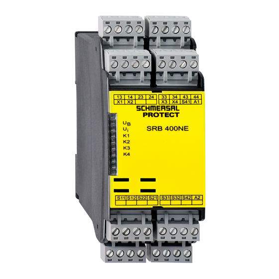
SRB 400NE
SRB 402NE
1
Advertisement
Table of Contents

Subscribe to Our Youtube Channel
Related Manuals for schmersal SRB 400NE


Summary of Contents for schmersal SRB 400NE
-
Page 1: Table Of Contents
Operating principle and settings Further technical information can be found in the Schmersal 5.1 LED functions......... .3 catalogues or in the online catalogue on the Internet: 5.2 Description of the terminals . -
Page 2: Warning About Misuse
They are used for the safe Outputs: evaluation of the signals of positive break position switches for safety Number of safety contacts: functions or BN20-2rz type magnetic safety sensors from Schmersal. Number of auxiliary contacts: SRB 402NE: 2 Switching capacity of the safety contacts:... -
Page 3: Safety Classification
The electrical connection may only be carried out by Fig. 1 Fig. 2 authorised personnel in a de-energised condition. The SRB 400NE does not have the auxiliary contacts 57-58 and 67-68 Wiring examples: see appendix Setting the pull-in delay (only SRB 402NE) 5. -
Page 4: Set-Up And Maintenance
Operating instructions SRB 400NE Safety-monitoring module SRB 402NE 6. Set-up and maintenance The following safety sensors from Schmersal meet the requirements: 6.1 Functional testing BN 20-2rz The safety function of the safety-monitoring module must be tested. The following conditions must be previously checked and met: Caution! When sensors with LED are wired in the control circuit 1. -
Page 5: Actuator Configuration
X3 X4 X3 X4 Fig. 10 Fig. 11 8.4 Flowcharts Flowchart SRB 400NE / SRB 402NE (Fig. 12) Fig. 13 a) Operating voltage U b) Preliminary limit switch S32-S42; c) Feedback circuit X3-X4; d) Limit switch S12-S22;... - Page 6 We hereby certify that the hereafter described components both in their basic design and construction conform to the applicable European Directives. Name of the component: SRB400NE / SRB402NE Description of the component: Safety-monitoring module for guard door monitoring and BNS20-2rz type magnetic safety switches from Schmersal Relevant Directives: Machinery Directive 2006/42/EC EMC-Directive 2014/30/EU RoHS-Directive...
Need help?
Do you have a question about the SRB 400NE and is the answer not in the manual?
Questions and answers