Advertisement
Advertisement
Table of Contents

Subscribe to Our Youtube Channel
Related Manuals for Ergomotion 40+ Series


Summary of Contents for Ergomotion 40+ Series
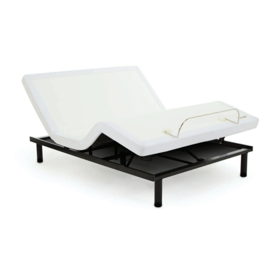
- Page 1 OWNER’S MANUAL 40+ Series...
-
Page 2: Table Of Contents
Connecting Strap ....................9 been dropped into water. Ergomotion adjustable bed bases are designed solely for in-home use. This base was not designed as a hospital bed and is not Syncing Two Bases . -
Page 3: Safety Precautions And Usage Statements
parts list safety precautions and usage statements Before discarding the packing materials - ensure all the parts are accounted for. Product Ratings: Fabric Care: The lift motors are not designed to operate continuously for more To prolong the life of your fabric, protect from direct sunlight whenever possible. -
Page 4: Base And Remote Overview
base and remote overview quick reference guide Not to scale. For illustration purposes only. Read all instructions before beginning installation. Head Motor CONTROL BOX OVERVIEW ELECTRONICS OVERVIEW Head Motor Foot Motor Lifts and lowers Lifts and lowers head portion of the foot portion of the Power Cord (D) base. -
Page 5: Installation Guide
Ensure the mattress on top. that the Power Supply and all attached cords are directed toward the desired surge protector. For customer support, visit www.ergomotion.com or call: 1-888-550-3746 For customer support, visit www.ergomotion.com or call: 1-888-550-3746... -
Page 6: Emergency Battery Backup Pack
emergency battery backup pack connecting strap (optional) Store the battery pack in a convenient location for emergency use. If any split setup is being installed, plastic connecting straps are provided (one per base) to secure the bases to- (4) 9 Volt batteries are required to operate the power down feature and are NOT included. gether. -
Page 7: Syncing Two Bases
syncing two bases (optional) headboard bracket installation guide (optional) A Y-Cord is included with the base. Not available on Queen, Full or Full-Long size bases. Headboard Brackets are an optional accessory and are not included. The Y-Cord connects the two control boxes to a single remote for the synchronization of two bases. A 9/16”... - Page 8 Plug bed base into a different electrical outlet, or test current outlet with another working appliance (a grounded, electrical surge protector is recommended). If issue is not resolved by following the instructions above, locate serial number on warranty card or back of remote and call Ergomotion Customer Service: US 1-888-550-3746...
-
Page 9: Español
Power Cord (1) = Cable eléctrico (1) Head motor = Motor de la cabecera completa sobre la garantía, visite www.ergomotion.com o lea la tarjeta de garantía mantenga separada de la pared harán contacto con los apoyos de la plataforma de Power Supply (1) = Fuente de energía (1) - Page 10 Girar la correa y conectar lado (b) de perno de la pata. Asegure la correa desplazando PASO 3: Para instalar los soportes de la cabecera, vea las instrucciones detalladas en la Para asistencia al cliente, visite www.ergomotion.us o llame a: 1-888-550-3746 llave de 9/16 para apretar los tornillos.
-
Page 11: Français
F) Battery Backup Box = Boîte de batterie de secours (1)* Foot Motor = Moteur du pied Ceci est normal. Les lits ajustables de Ergomotion sont créés pour l’utilisation individuelle à la maison. G) Connecting Strap = Sangle reliante (1)‡* Control Box = Boîte de contrôle Cette base n’est pas créée pour l’utilisation comme lit d’hôpital et elle ne satisfait pas les... - Page 12 Pour installer la cale d’espacement en plastique et la plaque d’attachement, vous gauche. Pour service consommateurs, allez au site web www.ergomotion.com ou appelez le avez besoin de (2) boulons longs et (2) écrous. Situez la cale d’espacement et la plaque ÉTAPE 2: Enlevez le sommier de la boîte en tenant le dessous de la boîte vers le haut.
- Page 13 notes notes...
- Page 14 Nationwide Customer Service ©2014 Ergomotion Inc V_003 09/2014 Phone 1.888.550.3746 1.805.979.9399 Email info@ergomotion.com www.ergomotion.com Serial Number:...
Need help?
Do you have a question about the 40+ Series and is the answer not in the manual?
Questions and answers