Table of Contents
Advertisement
Quick Links
CAUTION - Before performing any service
Operation on any pump, be sure that all
pressure has been relieved from BOTH
SIDES of the system.
CAUTION - Before performing any service
operation on any pump, disconnect or lock
off power supply.
CAUTION - Before starting pump, be sure
that any resulting machine function will not
endanger persons or equipment.
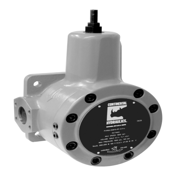
PRODUCT IDENTIFICATION
Each pump has an Ordering Code stamped on its
nameplate. See Figure 1 for the location of the
Ordering Code.
Model Code
Installation, Startup, Operating Instructions, Parts Pages, Repair Procedures
PVR50-
50B15-RF-0-521-L
RATI NGS
r
r pm
v
m
l
/ r
I N
3
/ r
p
ps i
p
bar
S. U. S 200- 250 @ 100° F . / C. S. T . 21- 30 @ 49° C.
Figure 1
Form No. 256827 Rev. 11/08
SERVICE MANUAL
PVR50 Flanged Series Pump
This service manual applies to products with Ordering
Codes like the sample in Figure 2.
PVR50 - _ _ - _ - _ - 5 _ _ _ - L
Basic Pump
Pump Size
Pressure
Rotation & Mounting
Seal Type
Integral Operator
Design Letter
INSTALLATION
PUMP DRIVE AND MOUNTING
When mounting the pump and motor, care must be
taken to align the pump and motor shafts within .003
T.I.R. Direct inline through a jaw type/flexible web
coupling is recommended for all Continental pumps.
Tire-type flexing elements and chain-type drives are
not recommended. With belt drives, please consult
factory.
To avoid axial and radial end loading of the pump
shaft, do not couple the pump and motor shafts
rigidly. Allow freedom at the coupling for the two
shafts to ride independently.
To prevent end loading, the space between the pump
and motor shaft ends should be 3/4 inch (19.1 mm)
for PVR50 pumps, or as the coupling manufacturer
specifies.
PIPING AND RESERVOIR
The pump should be mounted with a minimum
number of elbows or fittings. The pump suction
should be at least two (2) inch (50.8 mm) tube/pipe
for PVR50 pumps and 2-1/2 inch (63.5 mm) tube/pipe
for PVR50-70B pumps.
"L" Design Series
Figure 2
1
Advertisement
Table of Contents

Related Manuals for Continental Hydraulics PVR50 Flanged Series


Summary of Contents for Continental Hydraulics PVR50 Flanged Series
- Page 1 SERVICE MANUAL PVR50 Flanged Series Pump Installation, Startup, Operating Instructions, Parts Pages, Repair Procedures “L” Design Series This service manual applies to products with Ordering Codes like the sample in Figure 2. PVR50 - _ _ - _ - _ - 5 _ _ _ - L...
- Page 2 For any system and combination of piping except 5. Rotate pump and motor by hand to insure free High Water Based Fluids (HWBF), the vacuum at the rotation. pump inlet must not exceed seven (7) inches of Mercury, (5 inch Hg. for fire resistant fluids). HWBF 6.
- Page 3 The pressure adjusting screw is located at the end Stop adjustment of the volume screw when pressure face of the compensator chamber. See parts page begins to drop. See Sales Catalog for complete item number 30. The adjusting screw has a right pump performance specifications.
- Page 4 PVR50 PARTS DRAWINGS "D" Flange Mounting Code XXB5L (50B & 70B Only) See Page 6 for Controls Options. Mechanical Options Code 21 Code 13 Double End Drive Shaft Tandem Pump Mounting; 9 Tooth Spline, “A” Mounting Code 22 Tandem Pump Mounting; 13 Tooth Spline, “B” Mounting Code LF Left Hand Rotation (counterclockwise) (Not Shown) Code 23...
- Page 5 PVR50 PARTS LIST ITEM CODE PART DESCRIPTION ITEM CODE PART DESCRIPTION REQ’D REQ’D 32A, 42A, 50B 250240 Pressure Adj. Screw Ass’y. 1 17, 21, 22, 550615 Pump Body (Std.) 8, 9 256509 O-Ring Union 2400, 2500 8, 9 256508 Flow Control Valve 18** ,24** ,25** 550641 Pump Body (Std.)
- Page 6 PVR50 PARTS DRAWINGS Control Options Code 17 Code 2400 Dual Pressure Control Without Integral Valve Dual Volume Control Without Integral Valve (32A, 42A, and 50B Only) Code 18** Dual Pressure Control With Integral Valve Code 24** Dual Volume Control With Integral Valve PRESSURE RATE CONTROL VALVE (CODE 8 ONLY)
- Page 7 PVR50 PUMP REPAIR PROCEDURES REASSEMBLY PROCEDURE 1. Clean and inspect parts to determine which parts are worn enough to require replacement. DISASSEMBLY PROCEDURE NOTE: Disassembling pump to change 2. Assemble the new bearings (21) in the housing components, or for any other reason, may and cover.
- Page 8 5505 West 123rd Street Savage, MN 55378 Phone: (952) 895-6400 Fax: (952) 895-6444 www.continentalhydraulics.com Because Continental Hydraulics is continually improving its’ products, specifications and appearance are subject to change without notice. Form No. 256827 Rev. 11/08 © 2008, Continental Hydraulics. Printed in U.S.A...
Need help?
Do you have a question about the PVR50 Flanged Series and is the answer not in the manual?
Questions and answers