Table of Contents
Advertisement
Quick Links
Advertisement
Table of Contents

Related Manuals for Telit Wireless Solutions BlueMod+S50/AI


Summary of Contents for Telit Wireless Solutions BlueMod+S50/AI
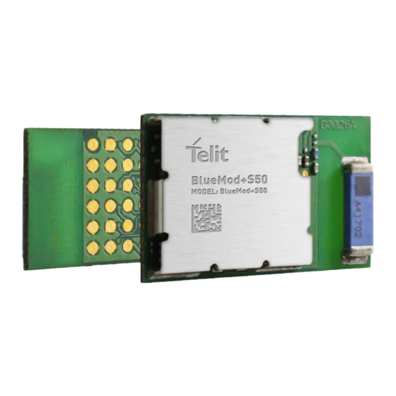
- Page 1 BlueMod+S50 Hardware User Guide 1VV0301505 Rev. 1 – 2018-03-12...
- Page 2 BlueMod+S50 Hardware User Guide SPECIFICATIONS ARE SUBJECT TO CHANGE WITHOUT NOTICE NOTICE While reasonable efforts have been made to assure the accuracy of this document, Telit assumes no liability resulting from any inaccuracies or omissions in this document, or from use of the information obtained herein.
- Page 3 BlueMod+S50 Hardware User Guide USAGE AND DISCLOSURE RESTRICTIONS License Agreements The software described in this document is the property of Telit and its licensors. It is furnished by express license agreement only and may be used only in accordance with the terms of such an agreement.
- Page 4 BlueMod+S50 Hardware User Guide APPLICABILITY TABLE PRODUCTS BLUEMOD+S50/AI/CEN BLUEMOD+S50/AP/CEN 1VV0301505 Rev. 1 Page 4 of 53 2018-03-02...
-
Page 5: Table Of Contents
BlueMod+S50 Hardware User Guide CONTENTS INTRODUCTION ................7 Scope ..................7 Audience ..................7 Contact Information, Support ............7 Text Conventions ............... 8 Related Documents ..............8 OVERVIEW .................. 9 GENERAL PRODUCT DESCRIPTION ........10 Feature Summary ..............10 Applications ................11 Block Diagram ................ - Page 6 BlueMod+S50 Hardware User Guide Antenna-Gain and Radiation Pattern for BlueMod+S50/AI ..31 MECHANICAL CHARACTERISTICS ......... 33 Dimensions ................33 Recommended Land Pattern ............ 33 Re-flow Temperature-Time Profile ..........34 AI Layout and Placement Recommendation ......35 OEM Layout and Antenna Selection in Respect to RED/FCC/IC Certification ................
-
Page 7: Introduction
BlueMod+S50 Hardware User Guide INTRODUCTION Scope This document provides information how the BlueMod+S50 can be integrated into customer systems. It addresses hardware specifications of the BlueMod+S50 and requirements of the hardware environments for the BlueMod+S50. The description text “BlueMod+S50” refers to all modules listed in the Applicability Table. -
Page 8: Text Conventions
BlueMod+S50 Hardware User Guide Text Conventions Danger – This information MUST be followed or catastrophic equipment failure or bodily injury may occur. Caution or Warning – Alerts the user to important points about integrating the module, if these points are not followed, the module and end user equipment may fail or malfunction. -
Page 9: Overview
It addresses hardware specifications of the BlueMod+S50 and requirements of the hardware environments for the BlueMod+S50. The term BlueMod+S50 is used as an abreviation and refers to both, the BlueMod+S50/AI and the BlueMod+S50/AP. If information is related to dedicated versions, the whole product name is used. -
Page 10: General Product Description
BlueMod+S50 Hardware User Guide GENERAL PRODUCT DESCRIPTION Feature Summary • Supports Bluetooth low energy • Qualified Bluetooth V5.0 Single Mode LE • Supports 2 Msym/s PHY for LE • Arm® CortexTM-M4F core for embedded profiles or application software • RF output power -20 up to +4dBm •... -
Page 11: Applications
BlueMod+S50 Hardware User Guide Applications The BlueMod+S50 is designed to be used in low power applications, like sensor devices. Some typical applications are described in this chapter. Supported profiles are: • Terminal I/O • GATT based LE-profiles Support for any additional profile is possible on request. 3.2.1. -
Page 12: Block Diagram
Block Diagram BlueMod+S50/AI onboard antenna 32MHz Serial Wire Debug nRF52832 optional 3.0V 32,768kHz VSUP Figure 1: BlueMod+S50/AI Block Diagram BlueMod+S50/AP 32MHz Serial Wire Debug nRF52832 optional 3.0V 32,768kHz VSUP Figure 2: BlueMod+S50/AP Block Diagram 1VV0301505 Rev. 1 Page 12 of 53... -
Page 13: Application Interface
BlueMod+S50 Hardware User Guide APPLICATION INTERFACE Power Supply BlueMod+S50 require a power supply with the following characteristics: Typical: 3,0V , min.: 1,7V , max.: 3,6V , thereby delivering > 25 mA peak BlueMod+S50 is designed to be powered from 3V coin cell batteries e.g. CR2032 directly, or any other power source complying with the given requirements. -
Page 14: Reset
BlueMod+S50 Hardware User Guide Reset BlueMod+S50 are equipped with circuitry for generating reset from two sources: • A reset is held active, when VSUP falls below the threshold of the brownout detector (V 1,2V … 1,7V), and is released when VSUP rises above V HYST The brownout detector also holds the reset active during power up, until VSUP >... -
Page 15: Serial Interface
BlueMod+S50 Hardware User Guide Serial Interface The serial interface of BlueMod+S50 is a high-speed UART interface supporting RTS/CTS flow control and interface-up/down mechanism according to the UICP protocol (refer to [2]). • Electrical interfacing is at CMOS levels (defined by VSUP; see chapter 6.3.1) •... - Page 16 BlueMod+S50 Hardware User Guide 4.3.2. 4-Wire Serial Interface If the host in question is sufficiently fast, a four-wire scheme may be successful. Connect the serial lines UART-RXD, UART-TXD as well as UART-RTS# and GND; leave UART- CTS# open. The host is required to stop sending data within a short time after de-assertion of UART-RTS# (there is room for up to 4 more characters at the time RTS# drops).
- Page 17 BlueMod+S50 Hardware User Guide If I/O line availability at the host side is extremely tight, 2 I/O lines could be saved by using the following scheme. This would come at the cost of • The host is not allowed to enter sleep mode. •...
- Page 18 BlueMod+S50 Hardware User Guide 4.3.5. UART Example Circuits MAX3241 +3V3 SHDN# BlueMod+S50 RS232 +3V3 VSUP 220R UART_TXD 220R UART_RXD RTS# 220R UART_RTS# CTS# 220R UART_CTS# IUR-OUT# 220R IUR-OUT# IUR-IN# 220R IUR-IN# can be left open 100n SigGND +3V3 DSUB9 (male) 100n DTE style connector pinout 100n 100n 100n...
-
Page 19: General Purpose I/O (Gpio)
BlueMod+S50 Hardware User Guide General Purpose I/O (GPIO) Functionality is defined project specific in the firmware used. It is possible to use the programmable digital I/Os GPIO[0:14] on the BlueMod+S50. Unused GPIO pins shall be left unconnected to stay compatible. There may be functions assigned to some in future versions of the firmware. -
Page 20: Serial Wire Debug Interface
BlueMod+S50 Hardware User Guide Serial Wire Debug Interface The Serial Wire Debug (SWD) interface (signals SWDIO, SWCLK) is normally not used in a customer’s product. It is reserved for debugging purposes. Leave SWDIO, SWCLK unconnected. Only if you intend to use them for debugging purposes, make them available. -
Page 21: Nfc Function
BlueMod+S50 Hardware User Guide NFC Function Functionality is defined project specific in the firmware used. The NFCT peripheral supports communication signal interface type A and 106 kbps bit rate from the NFC Forum. With appropriate software, the NFC peripheral can be used to emulate the listening device NFC-A as specified by the NFC Forum. -
Page 22: Slow Clock Interface
BlueMod+S50 Hardware User Guide Slow Clock Interface Even though an external slow clock is not required for BLE operation, consumption of power during power-down modes can be reduced by connecting an XTAL (32,768kHz) and two capacitors C1, C2 at pins XL-IN and XL-OUT. Limit Symbol Item... -
Page 23: Analog/Digital Converter (Adc)
BlueMod+S50 Hardware User Guide Analog/Digital Converter (ADC) Functionality is defined project specific in the firmware used. The ADC supports • 8/10/12-bit resolution, 14-bit resolution with oversampling • full swing operation 0V to VSUP • and up to 200kHz sample rate •... -
Page 24: Module Pins
BlueMod+S50 Hardware User Guide MODULE PINS Pin Numbering Figure 16: BlueMod+S50 Pin Numbering (Top View) 1VV0301505 Rev. 1 Page 24 of 53 2018-03-02... -
Page 25: Pin Description
BlueMod+S50 Hardware User Guide Pin Description Signal Alternate Type nRF52 Description Name VSUP1 +3,0V nom. B[5-8] C[5-8] Ground All GND pins must be connected AI: not connected ANT PIN AP: RF output (50Ω) NFCANT1 P0.09 NFC-Antenna NFCANT2 P0.10 NFC-Antenna TESTMODE# I-PU P0.08 Enable Testmode... -
Page 26: Firmware Depend Functions
BlueMod+S50 Hardware User Guide Firmware depend Functions Signal Type Function GPIO[0] none GPIO[1] none GPIO[2] none GPIO[3] GPIO[4] I-PU HANGUP GPIO[5] none GPIO[6] none GPIO[7] none GPIO[8] GPIO[9] none GPIO[10] none GPIO[11] none GPIO[12] none GPIO[13] none GPIO[14] none I: Input; O: Output; I/O: bidir; PU: pull-up; PD: pull-down; DIS: disconnected; PP: push-pull; Table 7: Firmware depend GPIO function Handling of Unused Signals Depending on the application, not all signals of BlueMod+S50 may be needed. -
Page 27: Electrical Characteristics
BlueMod+S50 Hardware User Guide ELECTRICAL CHARACTERISTICS Absolute Maximum Ratings Stresses beyond those listed under “Absolute Maximum Ratings” may cause permanent damage to the device. These are stress ratings only and functional operation of the device at these or any other conditions beyond those indicated under “Electrical Requirements” is not implied. -
Page 28: Dc Parameter
BlueMod+S50 Hardware User Guide DC Parameter All Module I/O pins are connected directly to the Nordic nRF52832 chip without signal conditioning except for some pull-up/pull-down resistors (as indicated). Therefore, the electrical characteristics are as documented in the Nordic nRF52832 data sheet [8]. 6.3.1. -
Page 29: Power Consumption And Power-Down Modes
BlueMod+S50 Hardware User Guide Power Consumption and Power-Down Modes 6.4.1. BlueMod+S50/AI CEN FW The following values are typical power consumption values in different states of operation. BlueMod+S50 configured as a peripheral device. VSUP = 3,0V, T = 25°C, all GPIO lines left open... -
Page 30: Rf Performance
BlueMod+S50 Hardware User Guide RF Performance 6.5.1. BLE Receiver VSUP = 3,0V, T = +25°C, PHY type: LE 1Msps Receiver Conditions BT Spec Unit PER ≤ 30,8% ≤ -70 Sensitivity -93,0 PER ≤ 30,8% ≥ -10 max received input level max PER report integrity 2,426 Ghz 50 <... -
Page 31: Antenna-Gain And Radiation Pattern For Bluemod+S50/Ai
BlueMod+S50 Hardware User Guide Antenna-Gain and Radiation Pattern for BlueMod+S50/AI If BlueMod+S50/AI is integrated into an end product while the recommendations depicted in chapter 7.4 are maintained, the following typical antenna radiation patterns can be expected. Radiation Pattern will depend on the end products PCB size, masses in the antenna environment, housing material and geometrics. - Page 32 BlueMod+S50 Hardware User Guide Figure 19: Typical Antenna Radiation Pattern at 2480MHz 1VV0301505 Rev. 1 Page 32 of 53 2018-03-02...
-
Page 33: Mechanical Characteristics
All dimensions are in millimeters. Dimensions BlueMod+S50/AI BlueMod+S50/AP +0,2 +0,2 17,0 17,0 -0,0 -0,0 Figure 20: BlueMod+S50/AI an /AP Dimensions Recommended Land Pattern 7x1,5=10,5 TOP VIEW 1,25 17,0 Figure 21: BlueMod+S50 Land Pattern 1VV0301505 Rev. 1 Page 33 of 53 2018-03-02... -
Page 34: Re-Flow Temperature-Time Profile
BlueMod+S50 Hardware User Guide Re-flow Temperature-Time Profile The data here is given only for guidance on solder and has to be adapted to your process and other re-flow parameters for example the used solder paste. The paste manufacturer provides a re-flow profile recommendation for his product. Figure 22: Soldering Temperature-Time Profile (For Reflow Soldering) Preheat Main Heat... -
Page 35: Ai Layout And Placement Recommendation
BlueMod+S50 Hardware User Guide AI Layout and Placement Recommendation BlueMod+S50/AI comprises a ceramic antenna, which as a component is soldered to the circuit board. The performance of the antenna has to be checked within the final integration environment. Adjacent PCBs, components, cables, housings etc. could otherwise influence the radiation pattern or be influenced by the radio wave energy. -
Page 36: Oem Layout And Antenna Selection In Respect To Red/Fcc/Ic Certification
BlueMod+S50 Hardware User Guide OEM Layout and Antenna Selection in Respect to RED/FCC/IC Certification Placement for BlueMod+S50/AP, is not restricted. For antenna port connection it is recommended to use a layout like shown in Figure 26. To keep specified radio power values the impedace of the RF trace connected to the antenna port shall be 50 Ohms. - Page 37 BlueMod+S50 Hardware User Guide a. Trace Design Impedance 50R Calculation Figure 27: RF Trace Impedance Calculation Parameters b. Trace Design Geometry It is important to avoid coupling of noise from digital lines to the RF trace and also to avoid RF signal coupling into power supply or analogue lines. Therefore, the following RF trace design geometry has been successfully used on the Telit standalone testboard and should be followed by OEM’s re-using BlueMod+S50/AP RED/FCC or IC Certifications.
-
Page 38: Housing Guidelines
• ABS is suggested Safety Guidelines According to SAR regulation EN 62479:2010 the BlueMod+S50/AI is not intended to be used in close proximity to the human body. Please refer to above-mentioned regulation for more specific information. In respect to the safety regulation EN 62368-1:2014 + AC:2015 all conductive parts of the BlueMod+S50 are to be classified as SELV circuitry. -
Page 39: Cleaning
GND pads (14) must be connected. Blocking capacitors not shown. In this example BlueMod+S50/AI is connected to an MCU supporting UICP , RTS/CTS flow control and Hangup. Figure 29: Typical Application Schematics 1VV0301505 Rev. 1 Page 39 of 53... -
Page 40: Compliances
BlueMod+S50 Hardware User Guide COMPLIANCES The BlueMod+S50/AI and BlueMod+S50/AP have been tested to fully comply with the appropriate EU, FCC and IC directives. CE testing is intended for end products only. Therefore, CE testing is not mandatory for a Bluetooth module sold to an OEM end product. However, Telit provides CE tested modules for customers in order to ease CE compliance assessment of end products and to minimize test effort. -
Page 41: Fcc Compliance
BlueMod+S50 Hardware User Guide FCC Compliance The BlueMod+S50/AI and the BlueMod+S50/AP have been tested to fulfill the FCC requirements. Test reports are available on request. 9.2.1. FCC Grant The actual version of the FCC Grant can be downloaded from the Telit Download Zone: https://www.telit.com/support-training/download-zone/... - Page 42 9.2.5. FCC RF-exposure Statement The BlueMod+S50/AI and BlueMod+S50/AP, if used with the antenna described in chapter 7.5 OEM Layout and Antenna Selection in Respect to RED/FCC/IC Certification, do comply with the FCC/IC RF radiation exposure limits set forth for an uncontrolled environment.
-
Page 43: Ic Compliance
BlueMod+S50 Hardware User Guide IC Compliance The BlueMod+S50/AI and BlueMod+S50/AP have been tested to fulfill the IC requirements. Test reports RSS-210 of Industry Canada are available on request. 9.3.1. IC Grant The actual version of the IC Grants can be downloaded from the Telit Download Zone: https://www.telit.com/support-training/download-zone/... - Page 44 , SAR evaluation has to be re-newed. Antenna Selection in Respect to RED/FCC/IC Certification 9.3.5. IC Labeling Requirements for the End Product Any end product integrating the BlueMod+S50/AI or BlueMod+S50/AP must be labeled with at least the following information: This device contains transmitter with FCC ID:...
-
Page 45: Bluetooth Qualification
BlueMod+S50 Hardware User Guide Bluetooth Qualification Blutooth qualification is in progress. RoHS Declaration RoHS evaluation is in progress. 1VV0301505 Rev. 1 Page 45 of 53 2018-03-02... -
Page 46: Packing
BlueMod+S50 Hardware User Guide PACKING The BlueMod+S50 modules are packed either as Tape&Reel or as tray packing. Tape&Reel Packing The BlueMod+S50 modules are packed using carrier tape in this orientation. 15 empty pockets as trailer per packing unit module type + label as example only 25 empty pockets as leader per packing unit pull off direction from reel Figure 30: Module Orientation in Carrier Tape... - Page 47 BlueMod+S50 Hardware User Guide 10.1.1. Tape The dimensions of the tape are shown in Figure 31 (values in mm): +0,1 12,0 -0,0 +0,1 +0,2 10x4,0=40,0 -0,1 -0,2 +0,1 10,9 -0,1 Figure 31: Carrier Tape Dimensions 10.1.2. Reel label content as example only XXXXXXXXXXXXXXXX name aaaaa-aa...
-
Page 48: Tray Packing
BlueMod+S50 Hardware User Guide Tray Packing 10.2.1. Module Orientation Figure 33: Module Orientation on Tray 10.2.2. Tray Dimensions Figure 34: Tray Dimensions Moisture Sensitivity Level Moisture Sensitivity Level (MSL) for BlueMod+S50 is 3. 1VV0301505 Rev. 1 Page 48 of 53 2018-03-02... -
Page 49: Evaluation Kit
BlueMod+S50 Hardware User Guide EVALUATION KIT Following evaluation kits are available: • BLUEEVA+S50/AI Please refer to [5] for additional informations. 1VV0301505 Rev. 1 Page 49 of 53 2018-03-02... -
Page 50: Safety Recommendations
BlueMod+S50 Hardware User Guide SAFETY RECOMMENDATIONS Read carefully Be sure the use of this product is allowed in the country and in the environment required. The use of this product may be dangerous and has to be avoided in the following areas: •... -
Page 51: Acronyms
BlueMod+S50 Hardware User Guide ACRONYMS TTSC Telit Technical Support Centre Universal Serial Bus Data Terminal Equipment UART Universal Asynchronous Receiver Transmitter Serial Peripheral Interface Input Output GPIO General Purpose Input Output CMOS Complementary Metal – Oxide Semiconductor MOSI Master Output – Slave Input MISO Master Input –... -
Page 52: Document History
BlueMod+S50 Hardware User Guide DOCUMENT HISTORY Revision Date Changes 2018-03-02 Initial release 2018-03-22 FCC and IC compliance updated 1VV0301505 Rev. 1 Page 52 of 53 2018-03-02...
Need help?
Do you have a question about the BlueMod+S50/AI and is the answer not in the manual?
Questions and answers