Table of Contents
Advertisement
Quick Links
U
M
ser
anual
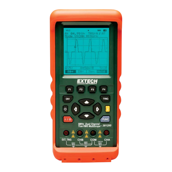
Model 381395
5MHz Dual Channel
True RMS Oscilloscope Datalogger
Test Equipment Depot - 800.517.8431 - 99 Washington Street Melrose, MA 02176
FAX 781.665.0780 - TestEquipmentDepot.com
Visit us at www.TestEquipmentDepot.com
Back to the Extech 381395 Product Page
FUNC
i
99 Washington Street
Melrose, MA 02176
Phone 781-665-1400
Toll Free 1-800-517-8431
Advertisement
Table of Contents

Related Manuals for Extech Instruments 381395


Summary of Contents for Extech Instruments 381395
- Page 1 Melrose, MA 02176 Phone 781-665-1400 Toll Free 1-800-517-8431 Visit us at www.TestEquipmentDepot.com anual Back to the Extech 381395 Product Page Model 381395 5MHz Dual Channel True RMS Oscilloscope Datalogger FUNC Test Equipment Depot - 800.517.8431 - 99 Washington Street Melrose, MA 02176...
-
Page 2: Table Of Contents
Table of Contents 1. GENERAL INFORMATION 1.1. EATURE VERVIEW 1.1.1. Universal SCOPE Mode 1.1.2. DATA Logger 1.1.3. Digital Multi-Meter 1.1.4. Frequency Counter 1.1.5. General 1.2. ARRANTY NFORMATION 1.3. RECAUTIONS MAINTENANCE 1.4. 1.5. AFETY NFORMATION IRST 1.6. YMBOLS AND ERMS 1.7. NPACKING THE NSTRUMENT 1.7.1. - Page 3 2.4. USB I 2-16 NTERFACE AND OWER INPUT TERMINAL 2.4.1. USB INTERFACE 2-16 2.4.2. Power Adaptor Input Terminal 2-16 3. USING THE SCOPE 3.1. METER OWERING THE 3.2. ISPLAY ACKLIGHT 3.3. “GENERAL SCOPE” ELECTING IN THE 3.4. SCOPE SETUP ELECTING ITEMS IN MENU 3.4.1.
- Page 4 5.1.1. RECORD MODE 5.1.2. RELATIVE MODE 5.1.3. COMPARE MODE 5.1.4. TREND PLOT 5.2. EASUREMENT ROCEDURES 5.2.1. DC V 5.2.2. AC V 5.2.3. Resistance 5.2.4. Continuity 5.2.5. Frequency 5.2.6. RPM 5.2.7. Pulse Width 5.2.8. Duty 6. SYSTEM SETUP 6.1. ONFIGURE THE UDIBLE EEPER 6.2.
- Page 5 9. MAINTAINING THE METER 9.1. ECTION VERVIEW RROR OOKMARK NOT DEFINED 9.2. TATIC ANDLING 9.3. LEANING THE ETER 9.4. TORING THE ETER 9.5. ALIBRATION 9.6. LI-ION B EPLACING AND ISPOSING OF THE ATTERY 9.6.1. Replacing the battery pack 10. APPENDICES 10-1 10.1.
-
Page 6: General Information
Unpacking the Test Tool Kit 1.1. Feature Overview The Model 381395 is a handheld, battery-operated Oscilloscope, True RMS Data Logger and Digital Multimeter designed and tested according to IEC Publication 1010-1 (EN 61010- 1:1993, Over voltage Category II) This instrument features: 1.1.1. -
Page 7: Digital Multi-Meter
USB PC interface for viewing and saving measurements and waveform data Auto power off (can be disabled) Display resolution: 132 x 128 pixels Designed to comply with safety standards: UL3111 and CSA C22.2 No.1010-1 Model 381395 Version 1.0 January 2008... -
Page 8: Warranty Information
1.2. Warranty Information EXTECH INSTRUMENTS CORPORATION warrants this instrument to be free of defects in parts and workmanship for one year from date of shipment (a six month limited warranty applies to sensors and cables). If it should become necessary to return the instrument for service during or beyond the warranty period, contact the Customer Service Department at (781) 890-7440 ext. -
Page 9: Safety Information: Read First
AC or DC DC – Direct Current AC – Alternating Current Fuse This product complies with the essential requirements or the applicable European laws or directives with respect to safety, health, environment and consumer protections Model 381395 Version 1.0 January 2008... -
Page 10: Standard
1.7.1. Standard One Meter Two Test leads One Lithuim-ION Battery (installed) One AC Power & Rechargeable Adaptor One CD (PC software) Meter to PC USB interface cable One Carrying case 1.7.2. Options Rubber Holster Model 381395 Version 1.0 January 2008... -
Page 11: Product Description
METER. Each will be addressed in the following sections. 1. The input Terminal area 2. The Keys area 3. The Display area 4. The USB Interface and Power input terminal FUNC Model 381395 Version 1.0 January 2008... -
Page 12: The Input Terminal Area
Use Common (Black) as single ground for low frequency measurements and for ACV, DCV, Ohm, Continuity, Hz, RPM, P/W and DTY measurements. Channel B For measurements on two signals use Channel B in combination with Channel A. External trigger The EXT.TRIG input accepts external trigger signals. Model 381395 Version 1.0 January 2008... -
Page 13: The Keys Area
Slope: Rising or Falling 1 2 3 Trigger setting mode (Auto or Normal) Trigger Level indicator Trigger point indicator Command Menu: Trigger level Command Menu: Single shot Command Menu: Trigger mode 6 7 8 (Setup) Model 381395 Version 1.0 January 2008... -
Page 14: Function Key
2.2.5. Command menu keys ( F1 through F4 are command menu soft-keys. These keys have a corresponding menu item displayed on the LCD. Press a soft-key to select the command term shown above the key. Model 381395 Version 1.0 January 2008... -
Page 15: Four Arrow Keys ( )
(2) When the command menu is in the Pos mode. The Trigger point indicator ( ) can be move. • : Press to move the Trigger point indicator leftward. • : Press to move the Trigger point indicator rightward. Model 381395 Version 1.0 January 2008... -
Page 16: Display Back Light ( )
The meter can store setups and waveforms in its internal memory for later recall. Sixteen (0- 15) setup and waveform memories are available. Memory mode. ( In Data Logger and Multimeter Mode All readings and waveforms can be held (frozen on the display) at any time in this mode. Model 381395 Version 1.0 January 2008... -
Page 17: The Display Area
▪ REMOTE: Indicates that the meter is communicating with a PC (USB Interface) ▪ BACK LIGHT ( ): Back light indicator ▪ Charging LINE ( ): Charging Battery indicator ▪ BATTERY ( ): Low battery indicator ▪ BUZZER ( ): Buzzer indicator Model 381395 Version 1.0 January 2008... - Page 18 : Channel mode status : Vertical mode: CHA, CHB or A&B : Horizontal mode: Normal, Roll : When pressing key in Scope mode only, the Memory Address appears at the top-right corner of the display area. Model 381395 Version 1.0 January 2008...
- Page 19 ROLL MODE operates when the horizontal division is between 1s and 5s Set the Measurement Function for Channel A Data Logger mode Displays DATA LOGGER Press to open Setup Press to change Edit mode PATH: Selects “DATA LOGGER” Model 381395 Version 1.0 January 2008...
- Page 20 : Set the Sampling type, : Sample (interval) Mode ▪ : Peak Detect Mode. The displayed value updates only when a new peak value is ▪ detected. : Set the Sampling interval time, 1Sec to 9,999Sec Model 381395 Version 1.0 January 2008 2-10...
- Page 21 The Command Menu for Record mode : Opens Setup mode for the Record mode : All data are set to zero. : Freezes the displayed value. The Setup mode for the Record mode : Set the Measurement Function Model 381395 Version 1.0 January 2008 2-11...
- Page 22 The Setup mode for Relative : Set the Measurement Function. Select from the following functions. DCV, ACV, OHM, BZ, FRQ, RPM, P/W or DTY. -2. Edit the Relative mode Reference point. (4-3) COMPARE MODE Model 381395 Version 1.0 January 2008 2-12...
- Page 23 The Setup mode for the Compare function : Set the Measurement Function. Select from the following functions. DCV, ACV, OHM, BZ, FRQ, RPM, P/W or DTY. -2. Edit Compare mode high point. -3. Edit Compare mode low point. Model 381395 Version 1.0 January 2008 2-13...
- Page 24 : Starts the graph plot (using REF value as the centerline). The Setup mode for the Trend plot The Offset is the centerline value on the trend graph V/DIV is the Y axis (amplitude). H/Div is the X axis (time) Model 381395 Version 1.0 January 2008 2-14...
-
Page 25: The Command Menu
Mode PATH Command Menu Function Menu Div: G/Scope Pos: G/Scope General Trigger: G/Scope Scope Store/Recall: G/Scope D/Logger Data Logger Record/Relative/Compare Record Multimeter Trend plot Trend System setup System setup Edit mode: System setup Model 381395 Version 1.0 January 2008 2-15... -
Page 26: The Usb Interface And Power Input Terminal
(tip/ring/sleeve phone plug) end of the cable connects to the meter (top) and USB end connects to the PC USB port. 2.4.2. Power Adaptor Input Terminal If an AC/DC power adapter is to be used, ensure that the adapter is plugged into an appropriate live power source. Model 381395 Version 1.0 January 2008 2-16... -
Page 27: Using The Scope
Open the FUNCTION menu. ▪ General Scope ▪ Data Logger ▪ Multimeter (4 type) ▪ System Setup Use the arrow keys to highlight the item. Set the “GENERAL SCOPE”. PATH: Model 381395 Version 1.0 January 2008... -
Page 28: Selecting Items In Scope Setup Menu
Highlight Hz (□ Hz). Set Hz (■ Hz). Exit Observe that Hz is now the main reading. The Frequency unit appears at the top-left corner of the display area. (Refer to above picture DCV FRQ) PATH: Model 381395 Version 1.0 January 2008... -
Page 29: Changing The Graphic Representation
Change Div from Manual mode to AUTO mode. PATH: 1) Pressing increases the Horizontal Division (Time base). 2) Pressing decreases the Horizontal Division (Time base). 3) Pressing will change the division from MANUAL to AUTO ( ) mode. Model 381395 Version 1.0 January 2008... -
Page 30: Positioning The Waveform Of Ch A On The Screen
Channel B upward. 3.5.5. Positioning the Trigger Point Indicator on the Screen With the menu at right > , press key to change the command menu Div to Pos ( Default Screen PATH: Model 381395 Version 1.0 January 2008... -
Page 31: Acquiring The Waveform
Note: ROLL MODE operates when the horizontal division is between 1sec. and 5 sec. 3.6.2. Selecting AC-Coupling for INPUT A Highlight AC for INPUT A. Set the AC-coupling for INPUT A. Exit PATH: Use AC-coupling to observe a small AC signal that rides on a DC signal. Model 381395 Version 1.0 January 2008... -
Page 32: Triggering On A Waveform
: Rising or falling edge ①-3. : Trigger mode Normal or AUTO ② : Trigger level indicator ③ : Trigger point indicator 3.7.1. Setting Trigger mode (Tmode) Default command menu. Open the Trigger command menu. Model 381395 Version 1.0 January 2008... -
Page 33: Setting Auto Trigger Level
For quick operation, use the AUTO trigger mode to trigger on nearly all signals automatically. To optimize the trigger slope manually, perform the following: Default command menu. Open the Trigger command menu. Open the Trigger Setup. Highlight AUTO. Set AUTO. Exit. PATH: Model 381395 Version 1.0 January 2008... -
Page 34: Setting Normal Trigger Mode
Adjust the Trigger Level continuously. Observe the Trigger level indicator ( ) on the rightmost time division line. Exit. PATH: 1) Pressing moves the Trigger level indicator ( ) downward. 2) Pressing moves the Trigger level indicator ( ) upward. Model 381395 Version 1.0 January 2008... -
Page 35: Making A Single Acquisition
(Store, Recall, Exit) Memory Address (0~15) (M: 00) Memory field (M:00) appears at the top-right corner of the display area. Select the memory address where the screen is to be stored. Store the actual screen PATH: Model 381395 Version 1.0 January 2008... -
Page 36: Recalling Screen
Memory field (M:00) appears at the top-right corner of the display area. Select the memory address from which to recall the screen Recall the screen. PATH: The result will be a fixed image and therefore can not be edited or otherwise changed. Model 381395 Version 1.0 January 2008 3-10... -
Page 37: Using The Data Logger
Open the Data Logger Setup. Use the arrow keys to highlight an item. Set the desired item. Exit PATH: 4.1.1. Change the Sampling Type Use the arrow keys to highlight Sample Type (■ Time or □ Peak). Model 381395 Version 1.0 January 2008... - Page 38 [Ex-1] START ADD: 10001 Move the Cursor to highlight the most significant digit. [Ex-2] START ADD: 10001 • Press key to increase, key to decreases the highlighted digit. [Ex-3] START ADD: 12001 Exit PATH: Model 381395 Version 1.0 January 2008...
- Page 39 Press this key again to Stop. PATH: 9. Connect test leads to the source signal and observe the reading shown on the display. If the input signal is beyond the allowed range, an overflow message “OL” will be displayed. Model 381395 Version 1.0 January 2008...
-
Page 40: Changing The Measurement Function & Range
Use the arrow keys to highlight DATA LOGGER Set and Open the Data Logger. Press key to recall data. • Press the key to scroll up • Press the key to scroll down. PATH: Model 381395 Version 1.0 January 2008... -
Page 41: Using The Digital Multimeter
The relative mode measures to what degree the input value deviates from a reference value (the deviation is displayed as a % error). Difference (DIF) = Measured – Reference (REF) Error (ERR %) = Difference / Reference x 100 Model 381395 Version 1.0 January 2008... -
Page 42: Compare Mode
The REF is the centerline value on the trend graph, H/Div is the X axis (time) and V/DIV is the Y axis (amplitude). [F3] Clear: Erase the graph on display. [F4] Start: Starts the plotting using the REF value as the centerline. Model 381395 Version 1.0 January 2008... -
Page 43: Measurement Procedures
• Press key to change the Measurement Function: [Ex-1] DTY P/W RPM FRQ BZ OHM ACV • Press key to change the Measurement Function. [Ex-2] DCV ACV OHM BZ FRQ RPM P/W DTY Model 381395 Version 1.0 January 2008... - Page 44 “OL” will be displayed. Note. The LCD will indicate the measured value in numeric and Bar graph displays. If the voltage is too high, the measurement range will switch to the next higher range automatically. Model 381395 Version 1.0 January 2008...
-
Page 45: Resistance
3. Change the mode to Digital Multimeter. (skip this step if Digital Multimeter mode is set) Path: (Record, Relative, Compare mode or Trend plot) 4. Select BZ with the key. The BZ appears at the top-left corner of the display area. Model 381395 Version 1.0 January 2008... -
Page 46: Frequency
1. Insert the BLACK test lead in the input socket marked ‘COM’. 2. Insert the RED test lead in the input socket marked ‘CHA’. 3. Change the mode to Digital Multimeter. (skip this step if Digital Multimeter mode is set) Model 381395 Version 1.0 January 2008... -
Page 47: Pulse Width
(Record, Relative, Compare mode or Trend plot) 4. Select DTY with the key. The DTY appears at the top-left corner of the display area. 5. Connect test leads to the source signal and observe the reading shown on the display. Model 381395 Version 1.0 January 2008... -
Page 48: System Setup
Set the BAUD RATE (BPS) of USB To change the BAUD Rate (BPS): Press SYSTEM SETUP to access SYSTEM SETUP Use the arrow keys to highlight “BAUD RATE(BPS):”. Set the item. (Fixed 115200) Exit Path: Model 381395 Version 1.0 January 2008... -
Page 49: Time
01 to 12, and valid day values are 01 to 31. To change the Current Date: 1. Press SYSTEM SETUP to open SYSTEM SETUP mode. 2. Select “DATE SET:” with the key. So, the “Edit” appears at the bottom-left corner of the display area. Model 381395 Version 1.0 January 2008... - Page 50 Move the blinking cursor to the left with the key and to the right with the key. Pressing the key will increase the value of the blinking digit. Pressing the key will decrease the value of the blinking digit. Model 381395 Version 1.0 January 2008...
-
Page 51: Specifications
Class-2 transformer, Input: 120-240V AC 50/60Hz, Output: 5V DC 1A Display Type: Super-Twist 132 x 128 pixels Equipment Dimensions: 3.5”(90mm) width x 7.7”(195mm) depth x 1.6”(40mm) height Equipment Weight: 1.0 lbs. (480g) approx. without Holster Model 381395 Version 1.0 January 2008... -
Page 52: Technical Specifications
50 mV to 500V in 1, 2, 5 sequence Triggering Type CHA, CHB, External Coupling AC, DC Slope Rising (↑) or Falling (↓) edge Internal Trigger 2 / 20 Division Sensitivity Waveform Memory Waveform Memory 16 Shots Model 381395 Version 1.0 January 2008... - Page 53 Resolution Accuracy Impedance 1 kΩ 5 kΩ 0.001 kΩ ±(0.5%+5) 10 kΩ 50 kΩ 0.01 kΩ 600V DC or AC rms 100 kΩ 500 kΩ 0.1 kΩ ±(0.75%+10) 1 MΩ 5 MΩ 0.001 MΩ Model 381395 Version 1.0 January 2008...
- Page 54 100 kHz 0.01kHz 1 MHz 0.0001MHz 10 MHz 0.001MHz Range Resolution Accuracy 0 – 9,999 1 RPM ±(0.05%+5) Pulse Width [Full Auto Range] Range 2uS-500mS (Pulse Width > 2uS) % Duty Range 25% - 75% Model 381395 Version 1.0 January 2008...
-
Page 55: Usb Hid Device Installation
When the meter is connected to the PC and then powered up, the PC should display "Found New Hardware" and automatically install the Human Interface Device (HID) driver. HIDs do not require a custom USB driver (HIDs are built into the Windows operating system). Model 381395 Version 1.0 January 2008... - Page 56 3) Auto Run or simply double click on Setup.exe [Step 1: Choose Setup Language] [Step 2: Preparing to Install] [Step 3: Welcome…] [Step 4: Ready to Install the Program] [Step 5: Installing Software] [Step 6: Install Wizard Completed] Model 381395 Version 1.0 January 2008...
-
Page 57: Running The Application Software
The Software window will open as shown below: 8.4.1. Oscilloscope Mode 1) Click the [LINK] Button and then the [Start] Button. ①LINK Button, ②Screen Print, ③Set the System Time and Date ④Start / Stop Button Model 381395 Version 1.0 January 2008... -
Page 58: Dmm & Data Logger Mode
DCV, ACV, OHM, BZ, Hz, RPM, Pulse Width and Duty ⑧ Storing and Recalling Screens 8.4.2. DMM & Data Logger Mode 1) Click the [DMM & Logger] tap ① LINK Button, ② Start / Stop Button Model 381395 Version 1.0 January 2008... -
Page 59: Display Mode For Dmm & Data Logger Mode
- Pause: Freezes the displayed value - Clear: Erase for Logged data of display - Hold: Freeze the screen at any time - Recall: Displays stored readings and buffer statistics - Start: Start the Data Logger Model 381395 Version 1.0 January 2008... - Page 60 - Start: Starts plotting the graph using the Offset Plot Mode: Line or Dot value as the centerline. Offset: The centerline value on the trend graph V/Division: V/DIV is the Y axis (amplitude). H/Division: H/Div is the X axis (time) Model 381395 Version 1.0 January 2008...
-
Page 61: Maintaining The Meter
If the meter requires cleaning, wipe it with a cloth that is lightly dampened with water or a mild detergent. Do not use hydrocarbons, chlorinated solvents, or methanol-based fluids when cleaning the meter. Model 381395 Version 1.0 January 2008... -
Page 62: Storing The Meter
Handle the PCB Assembly by its edges or while wearing gloves. Note This instrument contains a LI-ION battery pack. Do not dispose of this battery pack with other solid waste. Used batteries should be disposed of by a qualified recycler or hazardous materials handler. Model 381395 Version 1.0 January 2008... - Page 63 Rotate the PCB Assembly 180 degrees. ① Remove the Rubber Key: ② Remove the Battery Pack: Remove the battery plug from the connector. 3. Install a new battery pack. 4. Reinstall the rear cover and secure the screws. Model 381395 Version 1.0 January 2008...
-
Page 64: Appendices
The Meter does not trigger if the trigger level is set above or below the waveform level. In AUTO (AT) mode, the trigger level does not have to be adjusted. In rare cases the instrument may require servicing. There are no internal user- serviceable parts. Model 381395 Version 1.0 January 2008 10-1... -
Page 65: Lcd Status
10. Appendices 10.2. LCD STATUS INDICATIONS BY FUNCTION 10.2.1. Function Menu & General Scope Mode Function Menu & General Scope 10.2.2. Data Logger Mode Data Logger 10.2.3. Multimeter / Record Mode Record Mode Model 381395 Version 1.0 January 2008 10-2... -
Page 66: Multimeter / Relative Mode
10. Appendices 10.2.4. Multimeter / Relative Mode Relative Mode 10.2.5. Multimeter / Compare Mode Compare Mode 10.2.6. Multimeter / Trend Plot Mode Trend Plot Model 381395 Version 1.0 January 2008 10-3... -
Page 67: System Setup Mode
Melrose, MA 02176 Phone 781-665-1400 Toll Free 1-800-517-8431 Visit us at www.TestEquipmentDepot.com Back to the Extech 381395 Product Page Test Equipment Depot - 800.517.8431 - 99 Washington Street Melrose, MA 02176 FAX 781.665.0780 - TestEquipmentDepot.com Model 381395 Version 1.0 January 2008...
Need help?
Do you have a question about the 381395 and is the answer not in the manual?
Questions and answers