Industrial Scientific Radius BZ1 Product Manual
The essential guide for
safety teams and
instrument operators
Hide thumbs
Also See for Radius BZ1:
- Product manual (104 pages) ,
- Quick start manual (3 pages) ,
- Replacement instruction (2 pages)

Related Manuals for Industrial Scientific Radius BZ1


Summary of Contents for Industrial Scientific Radius BZ1
- Page 1 Product Manual The Essential Guide for Safety Teams and Instrument Operators Edition: 7 May 30, 2018 Part Number: 17155915-1...
- Page 2 Industrial Scientific Corporation, Pittsburgh, PA USA Industrial Scientific Co., Ltd. Shanghai, China © 2016, 2017, 2018 Industrial Scientific Corporation All rights reserved. Published 2018. Version 9 www.indsci.com/radius...
-
Page 3: Table Of Contents
Contents General Information ............................1 Certifications .............................. 1 Warnings and Cautionary Statements ....................... 2 Recommended Practices ........................... 4 First-use Checklist ..........................4 Placement Guidelines ..........................4 Gas and site factors ........................... 4 Wireless and GPS factors ........................4 Maintenance ............................5 Settings .............................. - Page 4 Display Overview ............................. 31 Settings ................................ 35 Guidelines ..............................35 Accessing Settings ..........................35 Settings Overview ............................ 36 Display Overview (settings) ........................36 Working in Settings ..........................37 Reviewing and Editing Settings ....................... 38 Maintenance Options and Settings ...................... 39 Start-up Settings ..........................
- Page 5 Process At-a-glance ..........................71 Supplies and Preparation ........................72 Instruction ..............................72 Service and Warranty ..........................75 Service ..............................75 Guidelines ............................75 Supplies ............................... 75 Instruction ............................76 Warranty ..............................81 Limitation of Liability ..........................81 Appendix A ..............................83 Supplemental Information about Gases and Sensors ................
- Page 6 Table 2.4 Battery specifications ........................16 Table 2.5 Sensor specifications ........................18 Table 3.1 Package contents ........................27 Figure 3.1.A Hardware overview Radius BZ1 (front view; diffusion) ............29 Figure 3.1.B Hardware overview Radius BZ1 (back view; aspirated) ............30 Figure 3.2 Setup ............................31 Figure 3.3 Display-screen overview during operation ..................
- Page 7 Figure 6.3 Alarm-signal intensity ......................... 63 Figure 6.4 Alarm and peer-alarm display-screen samples ................64 Figure 6.5 Alarms, possible causes, and relative signal intensity ..............65 Example: Peer instruments with one in high alarm .................. 65 Figure 6.6 Warning display-screen samples ....................66 Table 6.1 Warnings and indicators;...
-
Page 11: General Information
The following apply to instruments that are to be used in compliance with the CSA certification: Radius BZ1 Area Monitor is CSA-certified according to the Canadian Electrical Code for use in Class I, Division 1 and Zone Classified Hazardous Locations within an ambient temperature range of T : -20 °C to +55 °C. -
Page 12: Warnings And Cautionary Statements
: -20 °C to +55 °C. This is applicable when the monitor is used in the diffusion or aspirated mode and has been calibrated to 50% LEL CH In addition to the certifications listed below, refer to the Industrial Scientific websites for the most up-to-date information about wireless product certifications. - Page 13 CHARGER L'ACCUMULATEUR DANS UN EMPLACEMENT DANGEREUX. The compatible charging power supply (17155923) and cord is to be connected and used only in a nonhazdardous location. When the Radius BZ1 or Radius Base is in a hazardous location, the charging power supply cap must be installed...
-
Page 14: Recommended Practices
• Train instrument users. Placement Guidelines To develop a placement plan for each unique, in-field application of Radius BZ1 instruments, keep in mind all relevant gas, site, and LENS™ Wireless (Linked Equipment Network for Safety) factors, which include but are not limited to the following. -
Page 15: Maintenance
Figure 1.1 Sample placement plan for instruments in a LENS group Table 1.4 Range guidelines for LENS Wireless connections Line-of-sight distance, maximum Radius BZ1 to Radius BZ1 300 m (328 yd) Radius BZ1 to Ventis Pro 100 m (109 yd) -
Page 16: Settings
Table 1.4. These recommendations are provided to help support worker safety and are based on field data, safe work procedures, industry best practices, and regulatory standards. Industrial Scientific is not responsible for determining a company’s safety practices or establishing its safety policies, which may be affected by the directives and recommendations of regulatory groups, environmental conditions, operating conditions, instrument use patterns and exposure to gas, and other factors. -
Page 17: Biased Sensors
• When the module is not installed in a Radius Base, its biased sensors will be powered by the module’s backup battery to help maintain sensor stability. When a biased sensor is in use and the Radius BZ1 emits a low battery warning or a low backup battery warning, complete the steps noted below. -
Page 18: Remote Sampling
The power requirements of biased sensors can exceed the setpoint for the low backup battery warning. When a sensor’s required power exceeds what the backup battery can supply, the Radius BZ1 will indicate a sensor error, so in some cases, the cause of sensor error for a biased sensor may need to be treated as a low backup battery warning as described above. -
Page 19: Care And Storage
• Industrial Scientific recommends the SafeCore Module be stored in the Radius Base; this will help support conservation of the module’s backup battery, a power source that maintains the module's clock and is needed when biased sensor are installed. -
Page 21: Product Information
The Radius BZ1 can be operated as a stand-alone gas-detection instrument for area monitoring. This is suitable for applications where the goal is use a Radius BZ1 in a manner that will alert nearby workers to gas hazards and provide optional, instructional messages for specific hazards. -
Page 22: Key Features
Key Features Modularity The Radius BZ1 Area Monitor consists of the SafeCore® Module and Radius Base. When installed in the Radius Base, the SafeCore Module, serves as the instrument's central processing unit. It houses the gas sensors, electronics, firmware, data log, settings, wireless radio, clock and clock battery, and the pump (aspirated instruments only). -
Page 23: Lens Wireless
• View instrument status summaries. Messaging Radius BZ1 instruments give the safety team a variety of options to provide instrument operators with customized on-screen messages**. This includes a custom start-up message, which displays during the power-on process. A unique instructional message, or "alarm action message", can be set for each of these gas events for each sensor: gas present (low alarm and high alarm), STEL, and TWA. -
Page 24: Compatibilities
Compatibilities Batteries and Power Supplies The battery pack that powers the Radius BZ1 Area Monitor is encased in the Radius Base. It is charged in a nonhazardous environment using its dedicated power supply and power cord. Table 2.1 Compatible batteries... -
Page 25: Docking Station And Software
Industrial Scientific. Sample Tubing Kits Industrial Scientific recommends the use of its Teflon-lined tubing kit (part number 18109206) when sampling for these gases, which are susceptible to absorption by other types of tubing materials: Chlorine ), Chlorine Dioxide (ClO ), Hydrogen Chloride (HCl), and Volatile Organic Compounds (VOCs). -
Page 26: Specifications
Specifications Instrument The Radius BZ1 takes gas readings every second and records readings-related data at its settable interval. Data are stored in the instrument data log, which has these characteristics: • Capacity for approximately 90 days of data for a unit that has six installed sensors and is set to record data every ten seconds. -
Page 27: Sensors
Table 2.4 Battery specifications Battery Radius Base battery SafeCore Module battery pack Charging cycles 1000 cycles — Battery charge temperature 0 − 50 °C (32 − 122 °F) — Nominal voltage 6.0 VDC 3.6 VDC Nominal capacity 12.0 Ah 1.1 Ah Nominal power 72.0 Wh 4.0 Wh... - Page 28 Table 2.5 Sensor specifications Gas type (abbreviation) Part number Ammonia (NH Carbon Monoxide (CO) 17156650-6 17156650-1 Properties Category Toxic and combustible Toxic Technology Electrochemical Electrochemical DualSense capable Installation locations Operating conditions Temperature range -20 to +40 °C -20 to +50 °C (-4 to +104 °F) (-4 to +122 °F) RH range...
- Page 29 Table 2.5 Sensor specifications Gas type (abbreviation) Part number Carbon Monoxide, high range (CO) Carbon Monoxide, low Hydrogen interference CO-Low H 17156650-H 17156650-G Properties Category Toxic Toxic Technology Electrochemical Electrochemical DualSense capable Installation locations Operating conditions -20 to +50 °C -20 to +50 °C Temperature range (-4 to +122 °F)
- Page 30 Table 2.5 Sensor specifications Gas type (abbreviation) Part number Carbon Monoxide and Hydrogen Sulfide (CO and H 17156650-J Properties Category Toxic Technology Electrochemical DualSense capable Installation locations Operating conditions Temperature range -20 to +50 °C -20 to +55°C (-4 to +131°F) (-4 to +122 °F) RH range 15–90%...
- Page 31 Table 2.5 Sensor specifications Gas type (abbreviation) Part number Chlorine (Cl Hydrogen (H 17156650-7 17156650-C Properties Category Toxic Toxic Technology Electrochemical Electrochemical DualSense capable Installation locations Operating conditions -20 to +50 °C -20 to +50 °C Temperature range (-4 to +122 °F) (-4 to +122 °F) RH range 15–90%...
- Page 32 Table 2.5 Sensor specifications Gas type (abbreviation) Part number Hydrogen Cyanide (HCN) Hydrogen Sulfide (H 17156650-B 17156650-2 Properties Category Toxic Toxic Technology Electrochemical Electrochemical DualSense capable Installation locations Operating conditions Temperature range -20 to +40 °C -20 to +50 °C (-4 to +104 °F) (-4 to +122 °F) RH range...
- Page 33 Table 2.5 Sensor specifications Gas type (abbreviation) Part number LEL (Methane) LEL (Pentane) 17156650-L 17156650-K Properties Category Combustible Combustible Technology Catalytic Catalytic DualSense capable 3 or 4 3 or 4 Installation locations Operating conditions Temperature range -20 to +55°C -20 to +55°C (-4 to +131°F) (-4°F to +131°F) RH range...
- Page 34 Table 2.5 Sensor specifications Gas type (abbreviation) Part number Nitric Oxide (NO) Nitrogen Dioxide (NO 17156650-D 17156650-4 Properties Category Toxic Toxic Technology Electrochemical Electrochemical DualSense capable Installation locations Operating conditions Temperature range -20 to +50 °C -20 to +50 °C (-4 to +122 °F) (-4 to +122 °F) RH range...
- Page 35 Table 2.5 Sensor specifications Gas type (abbreviation) Part number Oxygen (O Phosphine (PH 17156650-3 17156650-9 Properties Category Oxygen Toxic Technology Electrochemical Electrochemical DualSense capable Installation locations Operating conditions Temperature range -20 to +55 °C -20 to +50 °C (-4 to +131 °F) (-4 to +122 °F) RH range 5–95%...
- Page 36 Table 2.5 Sensor specifications Gas type (abbreviation) Part number Sulfur Dioxide (SO Volatile Organic Compounds (VOC) 17156650-5 17156650-R Properties Category Toxic Toxic Technology Electrochemical PID (10.6 eV) DualSense capable 3 or 4 Installation locations Operating conditions Temperature range -20 to +50 °C -20 to +50 °C (-4 to +122 °F) (-4 to +122 °F)
-
Page 37: Getting Started
A shipment may include the items listed below in Table 3.1. Each item should be accounted for during the unpacking process. If any item is missing or appears to have been damaged, contact Industrial Scientific (see back cover) or an authorized distributor of Industrial Scientific products. -
Page 38: Hardware Overview
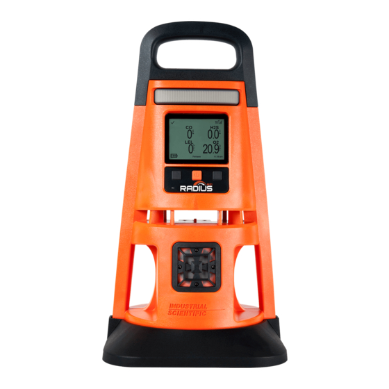
Hardware Overview The main hardware components of the Radius BZ1 Area Monitor are identified below in Figure 3.1.A and Figure 3.1.B (front view and back view, respectively). The front view features the diffusion instrument and shows the gas path, which leads to the sensor ports. The aspirated unit, as shown in the back view,... - Page 39 Handle Lights Display Power button Left button Right button ■ ■ Ambient-light Gas path (diffusion sensor only) Sensor ports Speaker Handle Boot Figure 3.1.A Hardware overview Radius BZ1 (front view; diffusion)
- Page 40 Write-on label (aspirated shown) Air inlet (aspirated only) Module locking screw Intrinsic safety (x2) power port Charging indicator Charging port Handle Boot Air inlet (diffusion Connector only) SafeCore Module port (shown empty) Figure 3.1.B Hardware overview Radius BZ1 (back view; aspirated)
-
Page 41: Setup
Setup Use the supplied screwdriver set to prepare the instrument for operation as described below in Figure 3.2. On the back of the Radius Base, locate Slide the module straight into its port. Push firmly to support the connection of the the SafeCore Module port. - Page 42 If the peer instrument does not have an assigned user such as "Tank 1", its serial number will display in place of the user assignment. Identifies a peer instrument as a Radius BZ1. Identifies a peer instrument as a Ventis™ Pro Series monitor.
- Page 43 Gas readings area This area communicates gas- readings information. It is also used to communicate alarm details and sensor status messages (e.g., Numeric view Text view calibration due symbol). Gas readings Gas, current reading, and unit of measure. Event symbols (gas-related) Gas present, positive over-range alarm.
- Page 44 Navigation bar Network information Identifies an instrument in the LENS peer group that may be experiencing an alarm or a group- Tank 3 peer connection issue. A symbol next to the device number will indicate the issue. Note: If no user (Tank 3 shown here) is assigned, the SafeCore Module's serial number will display.
-
Page 45: Settings
Accessing Settings Radius BZ1 settings, which reside in the SafeCore Module, can be accessed any time during operation by simultaneously pressing and holding the instrument's left and right buttons. As shown below, if the security- code screen is activated, settings are protected and the instrument's security code must be entered. If the entered value matches the security-code setting, the settings menu will display;... -
Page 46: Settings Overview
When working in settings, the instrument will wait approximately 30 seconds between button presses; when no button is pressed, it will exit the current setting screen and revert to the prior display screen. If that is the home screen, simultaneously press and hold the left and right buttons to re-enter settings. Settings Overview Instrument settings are organized by topic. -
Page 47: Working In Settings
In most cases, a setting is edited without moving to a second display screen as described in the first example shown below using the Peer Lost Warning setting. During editing, the right and left buttons generally perform the same function. The Radius BZ1 will monitor for gas when settings are in use and its alarms will be functional. -
Page 48: Reviewing And Editing Settings
■ ■ ■ ■ Move the Move the Edit the setting's Edit the value from Edit the value highlight bar to highlight bar to value "Off" to "On" from "Off" to Peer Lost Peer Lost "On" Warning Warning ■ ■ Confirm the Scroll up to Scroll down to... -
Page 49: Maintenance Options And Settings
• Maintenance • Start-up • Operation • Alarm • Sensor • Admin • Wireless From the access instruction and examples provided above, use the instrument buttons to review and adjust the instrument's settings described below in Tables 4.2 through 4.8. Maintenance Options and Settings The primary purpose of Maintenance is to provide the safety specialist with the opportunity to view maintenance information... -
Page 50: Start-Up Settings
Start-up Settings These settings allow the safety specialist to permit or prohibit all-user access to start-up options, information that will display during the power-on process. ■ ■ Move the Select the Move the highlight bar up highlighted highlight bar option down Table 4.3 Start-up settings Setting... -
Page 51: Operation Settings
Operation Settings These settings allow the safety specialist to permit or prohibit all-user access—during operation—to information and utilities. Access is set separately for each item. For example, the option to view instrument information may be permitted for all- user access, but the option to zero the instrument may be prohibited. -
Page 52: Alarm Settings
Alarm Settings These settings allow the safety specialist to set the values for each gas event that will cause the instrument to alarm. The specialist can make other choices about instrument behavior including the manner in which the instrument will communicate its alarm events. - Page 53 Table 4.5 Alarm settings Setting Description and options High Alarm Set the value to the gas concentration that will cause a gas-present, high-level alarm. STEL Alarm Set the value to the required short-term exposure limit (STEL) for the gas. STEL values reflect the cumulative measure of a gas over a defined period of time.
-
Page 54: Sensor Settings
Sensor Settings These settings allow the safety specialist to enable or disable for operation each installed sensor, and to set the gas concentration required for its calibration. The LEL correlation and PID response factors are also available for editing. ■ ■... -
Page 55: Admin Settings
Admin Settings Admin settings allow the safety specialist to control important aspects about how the instrument communicates with its operator. For example, a security code can be set to help restrict all-user access to settings. The safety specialist can also set the display-screen language, maintenance-related warnings, and other items. - Page 56 Table 4.7 Admin settings Setting Description and options Visual Blue lights Audible and Visual Chirp and blue lights Sync Interval Select the interval for each maintenance due warning. The "sync" interval controls the dock-due warning. Calibration Interval Interval type Value Bump Interval Sync One-day increment...
-
Page 57: Wireless Settings
Encryption Choose the manner in which transmitted, wireless data will be secured. Option Effect Default Use the Industrial Scientific encryption key. Custom* Use an encryption key other than the Industrial Scientific default option. *Requires the use of iNet or DSSAC. - Page 58 Table 4.8 Wireless settings Setting Description and options View Wireless Peers Set all-user access to view gas readings—during operation—for peer instruments that are within the instrument's assigned LENS group. Option Effect Peer instrument gas readings will be accessible on-demand during operation. Peer instrument gas readings will not be on-demand accessible during operation.
- Page 59 Table 4.8 Wireless settings Setting Description and options Option Effect The instrument will emit a warning when it becomes separated from its group. The instrument will not emit a warning when it becomes separated from its group. GPS Option Use this setting to allow or disallow the unit to obtain its GPS coordinates. Option Effect The instrument will attempt to obtain its GPS coordinates, at a set interval, for...
-
Page 61: Power
Power Charging the Battery Power On Power Off Maintaining Battery Charge Charging the Battery Before first use and as needed—in an area known to be nonhazardous—charge the Radius Base battery as described below in Figure 5.1. Charging can be done regardless of whether or not a SafeCore® module is installed. -
Page 62: Power On
Figure 5.1 Battery charging instruction Power on To power on the Radius BZ1 Area Monitor, press and hold the power button ( ) for approximately three seconds. Tones emitted from the speaker during the power-on process are of a lower decibel compared to the audible alarm signals. - Page 63 The unit emits a beep. Verify that the If the unit fails any part of its self-test, an error message will display. If the unit or its speakers are functional. operator detect problems, contact Industrial Scientific. Start-up sequence Set date and time Instrument information ■...
- Page 64 Radio firmware update Company message Compliance check (German-language instruments only) The SafeCore Module is installing ■ improvements. Acknowl- Answer Answer "no" "yes" edge message Pump test (aspirated units only) Place a finger over the opening at the end of the sampling line to block the flow of Once the pump test is complete, air.
- Page 65 Maintenance information Gas information The dock information (above left) indicates maintenance is due in the future These setpoints are provided for each (“days until”). gas: gas-present low alarm and high alarm, TWA alarm, STEL alarm, and The calibration information (above right) indicates the date on which the calibration gas.
-
Page 66: Shutdown
10 minutes of high alarm per day. Approximate run time when used with the Radius BZ1 Area Monitor that has a fully charged battery powering a diffusion unit that is operating at room temperature (25 °C [77 °F]) with CO, H... -
Page 67: Operation
• Verify the instrument's alarms are not turned off. Contact a supervisor if this message appears in the display's navigation bar, " Alarms Off." • If a compatible power supply from Industrial Scientific is in use, verify that the instrument is receiving power by checking the instrument display screen for the power-supply symbol ( ). LENS Wireless A LENS group can include RadiusBZ1 Area Monitors, Ventis®... -
Page 68: Live Monitoring
• To maintain membership in the LENS group, use these guidelines to assess potential signal reach: o a line-of-sight distance up to 300 m (328 yd) between two Radius BZ1 instruments. o a line-of-sight distance up to 100 m (109 yd) between a Radius BZ1 and a Ventis Pro that is facing the Radius instrument. - Page 69 This provides the required gateway connection for the transmission of Radius data to iNet. The LENS group can include up to six gas-detection instruments. • iNet iNet Now user Distance (meters) Radius BZ1 Ventis Pro LENS Wireless connection RGX Gateway iNet connection Smart device running iNet BLE connection Now Synch App Figure 6.1 Sample live-monitoring application...
-
Page 70: Gas Readings
Gas Readings After a unit has been powered on (its self-test and start-up sequence successfully completed) the gas readings will display. As noted earlier in the "Product Manual", this display screen is referred to as “Home." The display may vary based on the number of installed, operational sensors. As shown below, the home screen may display actual gas readings (numeric view) or a general statement about the readings (text view). -
Page 71: Utilities
• The instrument's serial numbers, versioning information, and the company, user, and site assigned to the instrument. • The number of days until the SafeCore® Module is due to be docked for maintenance. • The date each installed sensor is next due for calibration (or was last calibrated) and its span reserve percentage value. - Page 72 Instrument information Maintenance information (Calibration and span format) (Docking format) — — — — — — Next display Next display Next display screen screen screen Gas information Gas information (continued) Zero utility — — — — — — Next display Next display Next display screen...
-
Page 73: Alarms, Warnings, And Indicators
Take seriously all alarms, warnings, and indicators and respond according to company policy. Alarms Alarms notify instrument operators of danger. Alarm intensity is based on the event type and its source. The Radius BZ1 has alarms of four intensities; from highest to lowest they are: • High alarm • Low alarm •... - Page 74 Full-screen format Readings format (numeric view) Peer alarm format indicate the in-alarm peer instrument is Radius BZ1 or a Ventis Pro Series monitor, respectively. Figure 6.4 Alarm and peer-alarm display-screen samples The display screens shown above feature the symbols for a high alarm (...
- Page 75 Peer gas present (high-alarm event) Peer STEL event STEL Peer man down* MAN DOWN Peer panic* PANIC Peer Low Alarm Peer gas present (low-alarm event) Peer TWA event Figure 6.5 Alarms, possible causes, and relative signal intensity *When displayed in the peer alarm format, the in-alarm instrument is a Ventis Pro Series monitor. The example below describes and illustrates the sharing of alarm information for instruments that are operating as peers in a LENS group.
-
Page 76: Warnings
Warnings Warnings notify the instrument operator of a condition that needs attention. Warnings turn on and off repeatedly. The more urgent the warning, the shorter the time between on-off occurrences: a warning that repeats every ten seconds is more urgent than a warning that repeats every thirty seconds. -
Page 77: Resolving Failures And Errors
When addressing any failure, always respond according to company safety policy. Some failures and errors are easily resolved by qualified personnel as described below in Table 6.2. For other errors or failures, contact Industrial Scientific. When a recommendation action suggested below requires some form or maintenance or service, complete the work in an area known to be nonhazardous and follow all other instruction provided in "Maintenance"... - Page 78 The numeric error code indicates a specific issue or type of issue. When the error is described on the display screen, qualified personnel can attempt to resolve the issue. If no text accompanies the error code, contact Industrial Scientific or an authorized service center for assistance.
- Page 79 Table 6.2 Failures and errors The sensor failed calibration. Calibration results indicate the sensor’s span reserve percentage. When that value is less than 50%, the sensor will not pass calibration and is due for replacement. If the span reserve percentage indicates the sensor is greater than 50% check for the following: •...
-
Page 81: Maintenance
Tones emitted from the speaker during maintenance are of a lower decibel compared to the audible alarm signals. If needed, use the alarm muffler accessory from Industrial Scientific; if used, be sure to remove the muffler before instrument operation. -
Page 82: Supplies And Preparation
►► Skipped ─ Not relevant to the procedure. Supplies and Preparation Use Figure 7.1 as a guide to gathering supplies and preparing the calibration gas cylinders. Supplies • Calibration tubing (shipped with the instrument). • Calibration cup (shipped with diffusion instruments only). •... - Page 83 Calibration cup Calibration apply gas For diffusion units (shown), slide the To start the flow of gas, turn the prepared calibration cup into the gas regulator's knob in a counterclockwise Optionally skip the sensor. path. Press firmly; verify that the direction.
- Page 84 Calibration cup Bump test utility — For diffusion units (shown), slide the prepared calibration cup into the gas path. + Hold Press firmly; verify that the calibration cup edge is flush with the surface of the Start the utility SafeCore Module. For aspirated units, connect the calibration tubing to the pump inlet Bump test apply gas Bump test results...
-
Page 85: Service And Warranty
Warranty Service Service tasks that can be completed by Industrial Scientific customers are described in this "Product Manual." Table 8.1 indicates which parts and components are customer replaceable. All other service tasks should be performed only by Industrial Scientific or an authorized service center. -
Page 86: Instruction
Instruction Figure 8.1 provides disassembled views of the instrument, the Radius Base and SafeCore Module, identifying their parts and components. Use Table 8.1 to determine which items are customer replaceable and identify their part names and part numbers. SafeCore Module Radius Base Figure 8.1 Parts diagram for SafeCore Module and Radius Base Table 8.1 Parts table for SafeCore Module and Radius Base... - Page 87 Table 8.1 Parts table for SafeCore Module and Radius Base Diagram Part name Part Notes number Speaker grill kit 18109444 Includes speaker grill and replacement screws. Torque: 0.81 newton m (115 ounce-force inch). Speaker dust filter 18109445 Pack of 2. Boot 18109448 Includes replacement boot and T20 torx bit for use with...
- Page 88 Speaker grill replacement (or reattachment ) Press gently along the barrier edges to Place the speaker grill over the dust filter. Use the supplied screwdriver set to support adhesion. screw in the four speaker-grill screws. Refer to Table 8.1 for torque value. Pump inlet water barrier replacement —...
- Page 89 — Align the screw holes and place the new Tighten the screws; refer to Table 8.1 boot on the bottom of the Radius Base. for torque value. Figure 8.2 Service tasks, Radius Base Power off the instrument before disassembling or performing any service task. Module removal —...
- Page 90 Sensor replacement Do not touch the top of any sensor as this can contaminate or damage the item. Firmly hold the sides of the sensor, then Position the new sensor to align with its Place the sensor on the circuit board. pull it straight up and away from the connectors on the circuit board.
-
Page 91: Warranty
(including negligence), strict liability, products liability or any other theory of liability, will be limited to the lesser of Buyer’s actual damages or the price paid to Industrial Scientific for the Products that are the subject of Buyer’s claim. All claims against Industrial Scientific must be brought within one year after... - Page 92 Buyer acknowledges that it alone has determined the intended purpose and suitability of the goods purchased. It is expressly agreed by the parties that any technical or other advice given by Industrial Scientific with respect to the use of the goods or services is given without charge and at Buyer’s risk; therefore,...
-
Page 93: Supplemental Information About Gases And Sensors
Appendix A Supplemental Information about Gases and Sensors Cross Sensitivity and Toxic Gases A sensor is designed to detect for and measure the presence of a particular gas, the "target gas"; however, it may also respond to other gases. When this is the case, the sensor is said to have "cross-sensitivity" to another gas, which will interfere with the target-gas readings. - Page 94 For example, if the instrument reads 10% LEL in a pentane atmosphere, and was calibrated to methane, the actual percentage LEL is determined as follows: Locate the table cell where the sample gas (pentane) intersects with the calibration gas (methane). Multiply the cell's value (2.02) by the instrument's LEL reading (10%) to calculate the actual concentration of 20.2% LEL.
-
Page 95: Supplemental Information About The Extended Run Time Power Supply
Appendix B Supplemental information about the Extended Run Time Power Supply Figure B.1 Control drawing 1810D9387-200 revision 2... -
Page 96: Supplemental Information About The Intrinsically Safe Extended Run Time Power Supply
Appendix C Supplemental information about the Intrinsically Safe Extended Run Time Power Supply Figure C.1 Control drawing 1810D9387-200 revision 3... - Page 97 Vertriebshändler unserer Produkte oder ein Servicecenter bzw. eine Niederlassung von Industrial Scientific zu finden. Para buscar un distribuidor local de nuestros productos o un centro de servicio u oficina comercial de Industrial Scientific, visite www.indsci.com. 如需查找就近的产品经销商或 Industrial Scientific 服务中 心或业务办事处,请访问我们的网站 www.indsci.com...
Need help?
Do you have a question about the Radius BZ1 and is the answer not in the manual?
Questions and answers