Table of Contents
Advertisement
Quick Links
INSTRUCTIONS–PARTS LIST
Model PPM 100
Precision Pulse Volumetric
Fluid Flow Meter
Functions to display instantaneous flow, batch total flow, and cumulative total flow
20.7 bar (300 psi) Maximum Fluid Working Pressure
Flow Range is 30 cc/min. (1.0 oz/min.) to 1000 cc/min. (34 oz/min.)
Part No. 224–877, Series A
Intrinsically Safe for Class , Division 1, Group D
Hazardous Indoor locations
ENTITY PARAMETERS
Vmax
14 VDC
Imax
150 mA
Ci
6.3 F
Li
0 mH
Hazard of Using Fluids Containing Halogenated Hydrocarbons
Never use 1,1, 1-trichloroethane, methylene chloride, other halogenated hydrocarbon solvents or fluids contain-
ing such solvents in this equipment. Such use could result in a serious chemical reaction, with the possibility of
explosion, which could cause death, serious injury and/or substantial property damage.
Consult your fluid suppliers to ensure that the fluids being used are compatible with aluminum parts.
Refer to the Technical Data on page 15 for "Wetted Parts" information.
GRACO INC. P.O. BOX 1441 MINNEAPOLIS, MN 55440–1441
This manual contains important
warnings and information.
READ AND RETAIN FOR REFERENCE
COPYRIGHT 1992 GRACO INC.
WARNING
308–205
Rev. E
Supersedes D
01033
Advertisement
Table of Contents

Related Manuals for Graco PPM 100


Summary of Contents for Graco PPM 100
- Page 1 Consult your fluid suppliers to ensure that the fluids being used are compatible with aluminum parts. Refer to the Technical Data on page 15 for “Wetted Parts” information. GRACO INC. P.O. BOX 1441 MINNEAPOLIS, MN 55440–1441 COPYRIGHT 1992 GRACO INC.
- Page 2 Repair or replace worn or damaged parts immediately. 3. Follow the Pressure Relief Procedure for your fluid Use only Graco replacement parts. system dispensing device. IMPORTANT United States Government safety standards have been adopted under the Occupational Safety and Health Act. These stan-...
-
Page 3: Table Of Contents
See Data, page 15, for recommended barrier module. Accessories for Graco cable seal, part no. 110–458. For your safety , be sure to understand and follow Hazardous Location Wiring of Intrinsically Safe The purpose of such sealing or venting is to prevent Circuits instructions, below. -
Page 4: Installation Drawing For Csa Approval
Installation Drawing for CSA Approval Part No. 224–877 Intrinsically Safe For Class , Division 1, Group D Hazardous Location NOTE: This installation drawing is for use of the PPM100 with a remote monitor . A barrier module is not required if the PPM100 is used as a stand-alone meter (i.e. -
Page 5: Control Drawing For Fm Approval
Control Drawing for FM Approval Part No. 224–877 Intrinsically Safe For Class , Division 1, Group D Hazardous Location NOTE: This installation drawing is for use of the PPM100 with a remote monitor . A barrier module is not required if the PPM100 is used as a stand-alone meter (i.e. - Page 6 Cable Wiring and Dip Switch Settings When Using PPM 100 Flow Meter with PPD 200 Remote Display 235–616 (PPM 100 Meter used in Class , Division 1 Hazardous Location) Remote Display Dip Switch Tab Positions (Located on bottom of the control)
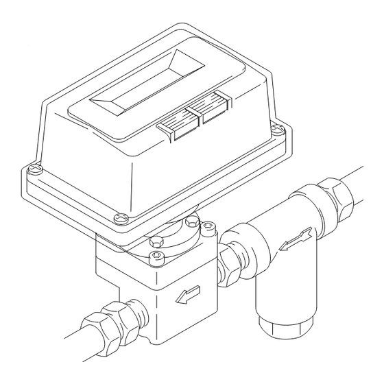
- Page 7 Installation Flow Meter Attach ground lug under screw Fluid Shutoff Valve Fluid Filter Fluid Shutoff Valve on outlet side on inlet side 01063 Fig. 2 Dust and Foreign Matter Flow Meter Location NOTE: Flow volume can only be measured at the lo- Avoid allowing dust or foreign matter from entering the flow meter by taking the following precautions: cation where the flow meter is installed.
-
Page 8: Operation
Operation WARNING When used with low viscosity fluids, such as sol- vent, the flow meter will not be accurate at low flow Pressure Relief Procedure rates under 50 cc/min (1.69 oz/min). See graph, To reduce the risk of serious injury, including page 16. - Page 9 10. If the flow meter accuracy is outside of your No Flow Volume Display acceptable limit, return the meter to Graco for recalibration or parts replacement. If there is no flow volume display, check the following:...
-
Page 10: Maintenance
Maintenance WARNING Cleaning the Meter Chamber Pressure Relief Procedure 1. Follow the Pressure Relief Procedure Warning, Before checking, cleaning, or servicing the meter, at left. always follow this procedure to reduce the risk of serious injury, including splashing fluid in the eyes 2. - Page 11 Maintenance 01034 01036 Connector Connector Power Pack Power Pack STEP 1: STEP 3: Remove the covers and connect the Install the new power pack in the me- new power pack. Do not disconnect the old power ter and install the covers. pack until the new power pack is connected.
-
Page 12: Parts
Parts M4 x 12 M5 x 25 Permanently bonded to meter 01031... -
Page 13: Graco Phone Numbers
187–570 LABEL, warning 110–504 FITTINGS, 3/8 npt(m) TO PLACE AN ORDER , contact your Graco distribu- tor, or call Graco: 1–800–328–0211 Toll Free Replacement W arning labels are available at no cost. FOR TECHNICAL ASSIST ANCE , service repair infor- Changing the rotor may effect the meter accuracy . - Page 14 Part No. Length ft (m) 208–630 1/2 npt(m) x 3/8 npt(f); carbon steel and PTFE ; for non-corrosive fluids 235–790 PPM 100 235–616 25 (7.63) 210–071 3/8 npt(m) x 3/8 npt(f); stainless steel and 235–791 PPM 100 235–616 50 (15.25)
-
Page 15: Dimensions
Dimensions Weight: 672 g (24 oz.) 147 mm (5.8 in.) M6 x 8 thread 130 mm 5.1 in. 76 mm (3.0 in.) 20 mm (0.787 in.) 01134 Technical Data Maximum Fluid Working Pressure. 20.7 bar (300 psi) Fluid Viscosity Range . -
Page 16: Performance Chart
Graco distributor to the original purchaser for use. As purchaser’s sole remedy for breach of this warranty, Graco will, for a period of twelve months from the date of sale, repair or replace any part of the equipment proven defec- tive.
Need help?
Do you have a question about the PPM 100 and is the answer not in the manual?
Questions and answers