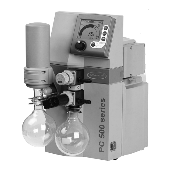
vacuubrand PC 510 NT Instructions For Use Manual
Chemistry pumping unit
Hide thumbs
Also See for PC 510 NT:
- Instructions for use manual (63 pages) ,
- Instructions for use manual (75 pages)

Related Manuals for vacuubrand PC 510 NT


Summary of Contents for vacuubrand PC 510 NT
-
Page 1: Part I
Part I page 1 of 106 Technology for Vacuum Systems Instructions for use Part I of II PC 510 NT PC 511 NT PC 520 NT PC 610 NT Part I: PC 611 NT Safety information - Technical data -... - Page 2 2 of 106 Dear customer, Your VACUUBRAND diaphragm pumps are designed to provide you with many years of trouble-free service with optimal performance. Our many years of practical experience allow us tor provide a wealth of application and safety information. Please read these instructions for use before the initial operation of your pump.
-
Page 3: Reset / Language Selection
page 3 of 106 Reset / Language selection press both switch off C V C 300 0 V 2. 0 D e ut sch P or t uguê E n gl i sh Ρ yc cк ий Fr ançai s P ol s ki I t a l i ano N ede rl . -
Page 4: Table Of Contents
page 4 of 106 Contents Part I..............1 Reset / Language selection ..........3 Safety information! ............. 6 Important information! ................. 6 General information ................8 Intended use..................8 Setting up and installing the equipment ..........9 Ambient conditions ................11 Operating conditions ................. - Page 5 page 5 of 106 Configuration ..............60 Readjustment of CVC 3000 ..........62 Calibration in the factory ..........64 Cleaning the pressure transducer ........65 Part II.............. 66 Interface parameters ............69 Setting of the interface ..............70 Read commands ”CVC 2000” ............71 Write commands ”CVC 2000”...
-
Page 6: Safety Information
Read this manual carefully before installing or oper- ating the equipment. Observe the instructions con- tained in this manual. VACUUBRAND disclaims any liability for inappro- priate use of these pumps and for damage resulting from disregarding the instructions contained in this manual. - Page 7 page 7 of 106 ➨ DANGER indicates a hazardous situation which, if not avoided, will result in death or serious injury. + WARNING indicates a hazardous situation which, if not avoided, could result in death or serious injury. • CAUTION indicates a hazardous situation which, if not avoided, could result in minor or moderate injury.
-
Page 8: General Information
page 8 of 106 General information Remove all packing material from the packing box. Re- NOTICE move the product from its packing-box and retain all pack- aging until the equipment is inspected and tested. Re- move the protective caps from the inlet and outlet ports and retain for future use. -
Page 9: Setting Up And Installing The Equipment
page 9 of 106 + Do not use the pump to generate pressure. The pumps are designed for operation at ambient temper- NOTICE atures between +50°F and +104°F (+10°C and +40°C). Check the maximum temperatures if installing the pump in a cabinet or a housing. - Page 10 page 10 of 106 blocked. If there is an exhaust isolation valve, make sure that you cannot operate the equipment with the valve closed to avoid a risk of bursting! + Always provide a free and pressureless exhaust outlet to avoid damage to pump valves and risk of bursting of condenser glassware.
-
Page 11: Ambient Conditions
page 11 of 106 necessary to avoid a reduction of ventilation. Do not place the pumping unit on soft surfaces (e.g., rub- ber foam) during operation. This may reduce or block the fans’ air supply. Keep a minimum distance of 8 in (20 cm) between the cooling fan and surrounding items (e.g., hous- ing, walls, etc.). -
Page 12: Operating Conditions
page 12 of 106 To the best of our knowledge the equipment is in compli- NOTICE ance with the requirements of the applicable EC-directives and harmonized standards (see ”Declaration of Conformi- ty”) with regard to design, type and model. Directive IEC 1010 (EN 61010-1) gives in detail the conditions under which the equipment can be operated safely (see also IP degree of protection, ”Technical data”, pg. -
Page 13: Safety During Operation
page 13 of 106 Do not pump substances which may form deposits in- NOTICE side the pump. The pumps are not suitable for pumping substances which may form deposits inside the pump. De- posits and condensate in the pump may lead to increased temperatures even to the point of exceeding the maximum permitted temperatures. - Page 14 page 14 of 106 + Never operate this pump if it has a damaged cord or plug. If the pump is not working properly, has been dropped or has fallen into water, contact your pump service provider. + Prevent any part of the human body from coming into contact with vacuum.
- Page 15 page 15 of 106 using original manufacturer’s spare parts. • Ensure that no parts of your clothing, hair or fingers can be caught or drawn in at the inlet of the pump. Never insert fingers or drop any other object into the inlet or outlet.
- Page 16 page 16 of 106 gerous situation from arising if the controller starts a vacuum pump (in combination with a VMS Module A), switches an in-line valve or a coolant valve, or opens a venting valve. • Attention: If the controller is set to Autostart, the pro- cess will start immediately after a power failure with- out pressing any further key.
-
Page 17: Maintenance And Repair
Take advantage of our service seminars, which put special focus on the maintenance and repair of vacuum pumps. For details see www.vacuubrand.com. Wear parts have to be replaced regularly. In case of normal wear, the lifetime of the diaphragms and valves is >... - Page 18 page 18 of 106 + Switch off the pump. Disconnect the electrical pow- er cord and wait two minutes before starting mainte- nance to allow the capacitors to discharge. + Note: The pump may be contaminated with process chemicals, which have been pumped during operation. Ensure that the pump is completely decontaminated before maintenance commences.
-
Page 19: Technical Data
19 of 106 Technical data PC 510 NT PC 610 NT Type PC 511 NT PC 611 NT PC 520 NT PC 620 NT Maximum pumping speed 1.2 / 1.4 2.0 / 2.2 50/60 Hz (ISO 21360)* (2.0 / 2.3) (3.4 / 3.8) -
Page 20: Gas Inlet Temperatures
(ml) (500) Dimensions L x W x H approx. PC 510 NT / PC 610 NT 16.5 x 9.6 x 17.5 (419 x 243 x 444) in (mm) PC 511 NT / PC 611 NT 17.1 x 9.6 x 17.5 (435 x 243 x 444) - Page 21 page 21 of 106 Controller CVC 3000 ceramic diaphragm (alumina), Pressure transducer capacitive, absolute pressure, gas type independent Display LCD graphic display, illuminated Pressure units / scale (selectable) Torr, mbar or hPa Measuring range (absolute) 810 - 0.1 Torr (1080 - 0.1 mbar) Maximum control range (absolute)* 795 - 1 Torr (1060 - 1 mbar) Resolution...
-
Page 22: Wetted Parts
page 22 of 106 Wetted parts Components Wetted materials Pump Head cover; diaphragm clamping disc ETFE carbon fiber reinforced Diaphragm PTFE Valves FFKM O-rings Valve head ECTFE carbon fiber reinforced Tubing PTFE Gas ballast tube PTFE carbon reinforced Elbow fitting (at valve head) ETFE/ECTFE Pumping unit Inlet pumping unit... -
Page 23: Abbreviations
page 23 of 106 Abbreviations ETFE: Ethylene/Tetrafluoroethylene ECTFE: Ethylene/Chlorotrifluoroethylene FFKM: Perfluoro elastomer FPM: Fluoroelastomer PBT: Polybutylene terephthalate PET: Polyethylene terephthalate Polypropylene PPS: Polyphenylene sulfide PTFE: Polytetrafluoroethylene PVDF: Polyvinylidene fluoride Pump parts Position Component Position Component Overpressure safety relief Inlet device Outlet Coolant inlet Gas ballast valve... - Page 24 24 of 106 PC 510 NT PC 511 NT...
- Page 25 page 25 of 106 PC 520 NT for lower vacuum connection for upper vacuum connection PC 610 NT...
- Page 26 page 26 of 106 PC 611 NT PC 620 NT for lower vacuum connection for upper vacuum connection...
- Page 27 27 of 106 Rear side of pumping units (shown: PC 510 NT) Rear side CVC 3000 serial interface RS-232 C jacks for connection of VACUU•BUS components (e.g., coolant valve) Connection plug of the power supply venting connection vacuum connection...
-
Page 28: Use And Operation
page 28 of 106 Use and operation When switching on the controller CVC 3000 for the very first time, a menu to select the language of the controller menu is displayed. Select the de- sired language (e.g., ”English”) by turning the selection knob and press to confirm. - Page 29 Secure hose connections at the pump appropriately, e.g., with hose clamps, to protect against accidental detach- ment. The VACUUBRAND controller CVC 3000 can only be oper- ated with components compatible with the VACUUBRAND VACUU•BUS system, (see ”Accessories”, pg. 79). The vacuum controller CVC 3000 controls VACUUBRAND diaphragm pumps NT and optional in-line, coolant, and venting valves.
- Page 30 page 30 of 106 CVC 3000 The CVC 3000 is equipped with an internal capacitive pressure transducer with ceramic diaphragm. It measures the actual pressure independently of the gas type, and with reference to the vacuum, i.e., absolute. + Maximum permissible pressure: 21.8 psi (1.5 bar) ab- solute.
- Page 31 page 31 of 106 ➨ Affix the controller with its holding plate to the pumping unit (three Allen screws (f), 2.5 mm wide Allen key). Install the washers and screw the holding plate into position. ➨ Slip the enclosed molded PTFE hose onto the hose connection of the valve block at the inlet (a).
- Page 32 page 32 of 106 Connection of components at the controller At the rear side of the pumping unit and at the rear side of the second controller (only PC 520/620 NT) are VACUU•BUS jacks for con- nection of accessory components: in-line valve / coolant valve / external pressure transducer / external venting valve / level sensor / emission condenser Peltronic etc.
- Page 33 page 33 of 106 + The isolation cover protects against glass splinters in case of breakage, acts as ther- mal isolation to avoid condensation of hu- midity and is intended to absorb shocks. + Never block the gas outlet ((2) hose nozzle for tubing I.D.
-
Page 34: During Operation
page 34 of 106 During operation + Vent and dispose of potentially dangerous gases or vapors at the outlet of the pump appropriately. • Due to the high compression ratio, the pump might gen- erate overpressure at the outlet. Check pressure com- patibility with system components (e.g., exhaust tubing or exhaust valve) at the outlet. - Page 35 page 35 of 106 pumped in significant amounts. Check the pump regularly for external soiling and depos- its. Clean the pump if necessary to avoid an increase of the pump’s operating temperature. In case of overload, the motor is shut down by a self-hold thermal circuit breaker in the winding.
-
Page 36: Important Notes Regarding The Use Of Gas Ballast
page 36 of 106 Important notes regarding the use of gas bal- last Gas ballast is a continuous purge to keep the pump’s in- terior as clean as possible and to reduce the possibility of condensation inside the pump. + Air and pumped media might react inside the pump or at the outlet of the pump and form hazardous or explo- sive mixtures, when you use air rather than inert gas for the gas ballast. -
Page 37: Important Notes Concerning The Operation Of The Exhaust Waste Vapor Condenser
page 37 of 106 Important notes concerning the operation of the exhaust waste vapor condenser + Do never block the gas outlet ((2) hose nozzle for tub- ing I.D. 3/8” (10 mm)). The exhaust hose must always be unobstructed and pressureless to enable an unhin- dered discharge of gases. - Page 38 page 38 of 106 Permissible range of coolant temperature at the exhaust waste vapor condenser: 5 °F to 68 °F (-15°C to +20°C) Check hose connections prior to starting operation of the cooling system. Check coolant hoses regularly during operation. Removing the catchpots: Catchpot at outlet: Remove joint clip.
-
Page 39: Shutdown & Storage
page 39 of 106 Shutdown & storage The pump can be switched off under vacuum. Short-term: NOTICE Has the pump been exposed to condensate? Allow the pump to continue to run at atmospheric pres- sure for a few minutes. Has the pump been exposed to media which may damage the pump materials or form deposits? Check and clean pump heads if necessary. -
Page 40: Vacuum Controller Cvc 3000
page 40 of 106 Vacuum controller CVC 3000 When switching on the controller CVC 3000 for the very first time, a menu to select the language of the controller menu is displayed. Select the de- sired language, e.g., ”English” by turning the selection knob and pressing to confirm. - Page 41 page 41 of 106 Selection knob • Press to reach the set-up menu of the function • Turn to choose the parameter you want to modify • Press to select the parameter you want to modify • Turn to change the set value of the parameter •...
- Page 42 page 42 of 106 Vacuum control to a preset vacuum value (here: 100 mbar/Torr/hPa) (with NT pump / with NT VARIO pump) Actual pressure is in the range ”Set vacuum + hys- teresis” (with NT pump) / Actual pressure = ”Set vacuum”...
- Page 43 page 43 of 106 Notes on selecting the function The CVC 3000 controller can be adapted to the specific application by choosing the appropriate function depending on the connected compo- nents and the requirements of the application. Automatic detection of the components When switching on the controller, the configuration of the connected com- ponents is checked automatically.
- Page 44 page 44 of 106 ”Vac control” • With pressure preselection, controls a NT pump or an in-line valve to maintain two-point control of that pressure. • Coolant valve ’’Program’’ • Controls a pump or in-line valve based on time and pressure preselec- tions.
-
Page 45: Menu Guide
page 45 of 106 Menu guide Pump down Minimum Delay Duration - - - - - - Graphic - - - - - - Pump down - - - - - - - Back - - - - - - - 1013 . - Page 46 page 46 of 106 Vac control Set vacuum 75 Torr Hysteresis Auto Minimum Delay Vac control Duration - - - - - - Graphic - - - - - - - - - - - - - Back - - - - - - - 1013 .
-
Page 47: Pump Down Function
page 47 of 106 Pump down function ➨ Continuous pumping with pressure and time settings • Operation of a vacuum pump via in-line valve • Operation of a vacuum pump without in-line valve via VMS (Vac- uum Management System), see ”Accessories”, pg. 79. Preselections + Use the selection knob to select the parameters. - Page 48 page 48 of 106 The screen-shot shows the factory-set values. Pump down Pump down 10 mbar 00:00:00 00:03:50 Minimum Delay Duration - - - - - - Graphic - - - - - - - - - - - - - Back - - - - - - - When selecting ”Graphic”...
-
Page 49: Vac Control Function
page 49 of 106 Vac Control function ➨ Vacuum control to a preset vacuum value • Operation of a vacuum pump via in-line valve • Operation of a vacuum pump without in-line valve via VMS (Vac- uum Management System), see ”Accessories”, pg. 79. Preselections + Use the selection knob to select the parameters. - Page 50 page 50 of 106 + Delay: ”Delay” determines the time the pump (with VMS module and in-line valve) remains running and the coolant valve remains open af- ter the process has been stopped. The ”Delay” is adjustable in a range of 1-300 minutes or can be set to ”Off”...
- Page 51 page 51 of 106 Adjustment of the ”Set vacuum” during vacuum control: Dynamic, interactive adaptation: + Press the selection knob and keep pressed. + Turning the knob for a 1/4 turn to the left causes pump down. + Turning the knob for a 1/4 turn to the right causes venting. + When the knob is released, the current pressure value is used as new set value.
-
Page 52: Program Function
page 52 of 106 Program function ➨ Permits ten programs to be defined and stored, each with up to ten program steps with preset values for vacuum and time. + Edit: Use to define the preset values for the process run: Time: Defines either the process runtime for each program step to reach a preset vacuum level or, if programming a ”Step”, the runtime after having achieved the vacuum level. - Page 53 page 53 of 106 Editing: + To select row: turn and press selection knob. + To adjust parameter: turn the selection knob. + To confirm parameter: Press selection knob. Controller will accept change and jump to the next parameter in the same row. + After 5 seconds without a change, the parameter is assumed to be the current setting.
-
Page 54: Application Example
page 54 of 106 Attention: If the controller is set to ”Defaults”: ”On”, all stored pro- grams will be deleted. Application example Example Vacuum pump with in-line valve and/or Vacuum-Management-Sys- tem Module A: Pumping down with intermediate venting Program hh:mm:ss Vac Vent. -
Page 55: Vacuulan Function
55 of 106 VACUULAN function ➨ Optimizes vacuum control for vacuum networks (e.g., VACUUBRAND VACUU•LAN) • Operation of a vacuum pump via in-line valve • Operation of a vacuum pump without in-line valve via VMS (Vac- uum Management System), see ”Accessories”, pg. 79. - Page 56 page 56 of 106 This screen-shot shows the factory-set values. VACUULAN VACUULAN 40 mbar 00:00:00 00:13:00 Set vacuum 19 Torr Switch on 150 Torr Delay 15 min - - - - - - Graphic - - - - - - - - - - - - - Back - - - - - - - When selecting ”Graphic”...
-
Page 57: Application Examples
page 57 of 106 Application examples Assembly of a vacuum system + Assemble vacuum connection lines between controller, vacuum pump (diaphragm pump with in-line valve or Vacuum-Management-System) and vacuum application. + Assemble electrical connections. + Connect coolant if necessary. Vacuum for filtration and suction + Select ”Pump down”... -
Page 58: Vacuum For Gel Dryer, Drying Chambers And Vacuum Concentrators
page 58 of 106 Vacuum for gel dryer, drying chambers and vacuum concentrators + Select function ”Pump down” function. + Set ”Minimum” to prevent volatile components from evaporating. The process is stopped automatically as soon as ”Minimum” is reached. + Set a process time (”Duration”) if necessary. + Start process by pressing ”START/STOP”... -
Page 59: Vacuum For Vacuu•Lan Networks
page 59 of 106 the pressure does not increase at the end of the evaporation. + Set a value for ”Duration” if the process should be terminated auto- matically after a definite time. + Use ”Delay” to pump out condensate and clean the pump at the end of the process. -
Page 60: Configuration
page 60 of 106 Configuration In the ”Configuration” menu the device parameters are preselected. Preselections + Use the selection knob to select the parameters. + Adjustment: Adjustment of the pressure transducer under vacuum and/or at atmospheric pressure, see also section ”Readjustment of CVC 3000”, pg. - Page 61 page 61 of 106 up can occur and to provide appropriate safety measures. If necessary, the user has to check prior to starting the process if the option ”Autostart” is enabled. + Defaults: If ”Defaults” is set to ”Load”, the controller is reset to factory set values.
-
Page 62: Readjustment Of Cvc 3000
page 62 of 106 Readjustment of CVC 3000 The vacuum gauge was adjusted using factory standards, NOTICE which are traceable through regular calibration in an ac- credited laboratory (German Calibration Service) to the German national pressure standard. Depending on the process and/or accuracy requirements, check the adjust- ment and readjust if necessary. - Page 63 page 63 of 106 Adjustment under vacuum An adjustment under vacuum is only possible if the pressure is lower than 15 Torr (20 mbar) 0 mbar absolute. Evacuate the measurement connection of the CVC 3000 to a pressure < 0.1 Torr (mbar) (e.g.
-
Page 64: Calibration In The Factory
64 of 106 Calibration in the factory Control of measuring equipment The VACUUBRAND DKD calibration laboratory is accredited by the Physikalisch-Technische Bundesanstalt (PTB; German national institute for science and technology and the highest technical authority of the Fed- eral Republic of Germany for the field of meteorology and certain sectors of safety engineering) for the measurable variable pressure in the pres- sure range from 7.5*10... -
Page 65: Cleaning The Pressure Transducer
page 65 of 106 Cleaning the pressure transducer ➨ Attention: Never use a pointed or sharp-edged tool to clean the pressure transducer. ➨ Never touch the ceramic diaphragm of the pressure transducer with hard objects. ➨ Fill the measurement chamber with a solvent (e.g., benzene) and allow sufficient cleaning time. -
Page 66: Part Ii
Part II page 66 of 106 Technology for Vacuum Systems Instructions for use Part II of II PC 510 NT PC 511 NT PC 520 NT PC 610 NT Part II: PC 611 NT Interface parameters - Accessories - PC 620 NT... - Page 67 page 67 of 106 Contents Part I..............1 Reset / Language selection ..........3 Safety information! ............. 6 Important information! ................. 6 General information ................8 Intended use..................8 Setting up and installing the equipment ..........9 Ambient conditions ................11 Operating conditions .................
- Page 68 page 68 of 106 Configuration ..............60 Readjustment of CVC 3000 ..........62 Calibration in the factory ..........64 Cleaning the pressure transducer ........65 Part II.............. 66 Interface parameters ............69 Setting of the interface ..............70 Read commands ”CVC 2000” ............71 Write commands ”CVC 2000”...
-
Page 69: Interface Parameters
The factory-set read and write commands are completely compatible with the VACUUBRAND CVC 2000 controller (see sections ”Read / Write commands CVC 2000”). An extended instruction set is available using the... -
Page 70: Setting Of The Interface
page 70 of 106 Setting of the interface Set the interface parameters directly at the controller CVC 3000. The fac- tory set values are underlined. Edit and confirm the interface parameters in the ”Configuration” menu in ”RS-232” submenu using the selection knob. ➨... -
Page 71: Read Commands "Cvc 2000
page 71 of 106 Read commands ”CVC 2000” Command Operation Response Description XXXX mbar/ IN_PV_1 current pressure unit according to preselections Torr/hPa IN_PV_2 current frequency XX.X Hz pump speed 0XXXX VACUU•LAN 1XXXX continuous pumping 2XXXX vacuum control without automatic 3XXXX vacuum control with automatic X0XXX no coolant valve... -
Page 72: Write Commands "Cvc 2000
page 72 of 106 Write commands ”CVC 2000” Command Operation Response Description continuous pumping vacuum control without automatic vacuum control with automatic OUT_MODE function optional: sensitivity: low optional: sensitivity: normal optional: sensitivity: high 0001 to 0795 Torr or 0001 to 1060 mbar OUT_SP_1 set vacuum XXXX... - Page 73 page 73 of 106 ** If remote operation is selected or deselected, the user has to ensure that no dangerous status of the system can occur due to the change of the mode of operation, and must take appropriate safety precautions, especially if selecting remote operation interferes with a locally oper- ated active process.
-
Page 74: Read Commands "Cvc 3000
page 74 of 106 Read commands ”CVC 3000” Command Operation Response Description XXXX.X mbar/Torr/ IN_PV_1 current pressure unit according to preselections IN_PV_2 current speed XXX% 1-100% or ”HI” IN_PV_3 time XX:XX h:m process runtime (hours:minutes) XXXX.X XXXX.X IN_PV_X pressure pressure of all connected sensors ...mbar operation time of IN_PV_T... - Page 75 page 75 of 106 Command Operation Response Description 0XXXXX pump off 1XXXXX pump on X0XXXX in-line valve closed in-line valve open X1XXXX XX0XXX coolant valve closed XX1XXX coolant valve open XXX0XX venting valve closed XXX1XX venting valve open VACUU•LAN XXXX0X XXXX1X Pump down status process...
-
Page 76: Write Commands "Cvc 3000
page 76 of 106 Command Operation Response Description delay (hours:minutes) IN_SP_4 XX:XX h:m (00:00 = Off) switch off pressure (”Maximum” for IN_SP_5 XXXX mbar/Torr/hPa ”Vac control”, ”Minimum” for ”Pump down”) IN_SP_6 XX:XX h:m process runtime (hours:minutes) IN_SP_P1y time XX:XX:XX h:m:s time in program step y (0..9) IN_SP_P2y pressure... - Page 77 page 77 of 106 Command Operation Response Description 0001 to 0795 Torr or 0001 to 1060 mbar OUT-SP_1 set vacuum XXXX (hPa), unit according to preselection set vacuum with 0001 to 0795 Torr or 0001 to 1060 mbar OUT_SP_V XXXX venting (hPa), unit according to preselection OUT_SP_2...
- Page 78 page 78 of 106 * If remote operation is selected or deselected, the user has to ensure that no dangerous status of the system can occur due to the change of the mode of operation, and must also take appropriate safety precau- tions, especially if selecting remote operation interferes with a locally operated active process.
-
Page 79: Accessories
page 79 of 106 Accessories External pressure transducer VSK 3000, ..........636657 capacitive, ceramic diaphragm sensor 1080-0.1 mbar Coolant valve VKW-B, 24 V= ..............674220 Venting valve VBM-B / KF 16, 24 V= ............674217 VACUU•BUS Y-type adapter ..............636656 VACUU•BUS extension cable, 6.6ft (2m) ............612552 VACUU•BUS wall jack .................636153 Serial cable RS 232C, 9-pin, Sub-D .............637837 Level sensor....................699908... - Page 80 IEC plug- IEC socket to VMS. Conversion of VACUUBRAND valves with DIN plug to VACUUBRAND valves with VACUU•BUS plug: VACUUBRAND-valve with DIN Conversion kit valve cable with plug VACUU•BUS plug...
- Page 81 VCL-B 11 ............677209 On this page we offer only a small selection of VACUU•LAN options. Please contact VACUUBRAND for further ® information. For additional accessories such as vacuum valves, small-flange components, vacuum gauges or vacuum controllers refer to www.vacuubrand.com.
-
Page 82: Troubleshooting
page 82 of 106 Troubleshooting Fault Possible cause Remedy ❑ No display. ➨ Electrical power cord ✔ Plug in power cord. not plugged in, electri- Check fuse. cal supply failure? ➨ Device fuse blown? ✔ Identify cause of failure. Replace device fuse. ➨... - Page 83 page 83 of 106 Fault Possible cause Remedy ❑ Digital pressure ➨ Overpressure at the ✔ Release pressure imme- reading is flashing, pressure transducer, diately (risk of bursting). one blip*. pressure > 795 Torr (1060 mbar)? ❑ Warning triangle ➨ External venting valve ✔...
- Page 84 page 84 of 106 Fault Possible cause Remedy ❑ ”Pump down” func- ➨ Pressure below preset ✔ Confirm by pressing tion: Control stops, minimum pressure? START/STOP key. ”arrow down” is Change minimum pres- flashing. sure value if necessary. ❑ No function is dis- ➨...
- Page 85 page 85 of 106 Fault Possible cause Remedy ❑ Pump does not ➨ Pump too hot? ✔ Allow pump to cool down. achieve its ultimate Determine and eliminate vacuum or usual the cause of overheating. pumping speed. ➨ Deposits have been ✔...
-
Page 86: Replacing Diaphragms And Valves
page 86 of 106 Replacing diaphragms and valves + Please read section ”Replacing diaphragms and valves” com- pletely before starting maintenance. The pictures may show other versions of pumps. This does not change the method of replacing diaphragms and valves. + Never operate the pump if covers or other parts of the pump are disassembled. - Page 87 page 87 of 106 • Vent the pump and isolate it from the vacuum sys- tem before you start maintenance. The valves and diaphragms as well as the motor capac- NOTICE itors are wear parts. If the rated ultimate vacuum is no longer achieved or in case of increased noise level, the pump interior, the diaphragms and the valves must be cleaned and the diaphragms and valves must be checked...
-
Page 88: Cleaning And Inspecting The Pump Heads
page 88 of 106 Cleaning and inspecting the pump heads The replacement of the diaphragm and the replacement of the valves can be carried out separately. + To replace the valves, remove the head covers of one side of the pump along with the assembled valve heads and fittings. - Page 89 page 89 of 106 PC 520 NT / PC 620 NT: ➨ Remove the second controller and its holding plate. ➨ Unplug in the VACUU•BUS lines at the rear of the controller (b): Power supply line of the controller and control line of the in-line valve. Attention: Do not apply off-axis forces when removing plug connections! ➨...
- Page 90 page 90 of 106 View of the disassembled pump head parts (fig.: MD 4C NT VARIO) A: Head alignment pin / mark L: Fillister head screw B: Connecting rod M: O-ring C: Housing N: Valve D: Washer O: Valve head E: Diaphragm support disc P: Hose nozzle F: Diaphragm...
- Page 91 page 91 of 106 Fittings and tubing of the different pump models: PTFE connection tube to opposite side of pump PC 510/511/510 NT PC 610/611/620 Detach the coupling of the connection tube (V) to the other side of the pump as well as the hose connection to the inlet/outlet of the vacu- um system at the valve head (O).
-
Page 92: Replacing The Diaphragm
page 92 of 106 Replacing the diaphragm ➨ Disassemble head covers (J) to check the diaphragm (F). ➨ Unscrew four (pump with two heads) or eight (pump with four heads) Allen screws (H) with a 5mm wide Allen key. Remove both head covers (J) (pumps with two heads: only one head cover) together with valve heads (O) and connections. - Page 93 page 93 of 106 ➨ Position new diaphragm (F) between dia- phragm clamping disc with square head screw (G) and diaphragm support disc (E). + Note: Position diaphragm with pale side to- wards diaphragm clamping disc (facing pump chamber). + Make sure that the square head screw of the diaphragm clamping disc is correctly seated in the guide hole of the diaphragm support disc.
-
Page 94: Replacing The Valves
page 94 of 106 Replacing the valves ➨ Open the hinged cover of the connection fastener (Q) with a slotted screwdriver. Loosen connection fastener slightly. ➨ Turn the fillister head screw (L) with a Torx driver T20 at most one turn. + Do not detach the fillister head screw from the square nut (K). - Page 95 page 95 of 106 ➨ Insert O-rings (M) and valves (N). See figure for the correct position of the valves: + Inlet side (IN): Marked ”IN” next to the valve seat. The valve tongue points at the kidney-shaped orifice in the valve seat.
- Page 96 page 96 of 106 ➨ Bring the diaphragms (F) into a position, in which they are in contact with the housing (C) and centered with respect to the bore. ➨ Put on head cover (J) with valve heads (O) and connections attached. + Pay attention to the correct orientation of the head covers: Housing with head alignment pin: The head...
- Page 97 page 97 of 106 ➨ Tighten the fillister head screws (L) of the connection fasteners (Q) with a Torx driver T20. ➨ Close the hinged covers. Replace diaphragms and valves of the opposite side of the pump in the same way. ➨...
- Page 98 page 98 of 106 Assembling the second CVC 3000 controller (only PC 520 NT / PC 620 NT): ➨ Affix the controller with its holding plate to the pumping unit (three Allen screws (f), 2.5 mm wide Allen key). Install the washers and screw the holding plate into position.
-
Page 99: Replacing The Device Fuse
page 99 of 106 Replacing the device fuse ➨ Before replacing the fuse, switch off the pump. Discon- nect the electrical power cord. Wait two minutes after isolating the equipment from AC power to allow capaci- tors to discharge. Identify and eliminate the cause of failure before switching on the pump again. -
Page 100: Notes On Return To The Factory
page 100 of 106 Notes on return to the factory Repair - return - DKD calibration Safety and health of our staff, laws and regulations re- NOTICE garding the handling of dangerous goods, occupational health and safety regulations and regulations regarding safe disposal of waste require that for all pumps and other products, the “Health and safety clearance form“, see pg. - Page 101 page 101 of 106 We submit repair quotations only on request and always at the customer’s expense. If an order is placed, the costs incurred for problem diagnosis are offset from the costs for repair or from the purchase price, if the customer pre- fers to buy a new product instead of repairing the defec- tive one.
- Page 102 page 102 of 106 Scrapping and waste disposal: Dispose of the equipment and any components removed from it safely in accordance with all local and national safety and environmental requirements. Particular care must be taken with components and waste oil which have been contaminated with dangerous substances from your processes.
-
Page 103: Warranty
103 of 106 Warranty VACUUBRAND shall be liable for insuring that this prod- uct, including any agreed installation, has been free of de- fects at the time of the transfer of risk. VACUUBRAND shall not be liable for the consequences... -
Page 104: Health And Safety Clearance Form
❑ sterilized. Date: ................ VACUUBRAND GMBH + CO KG Alfred-Zippe-Str. 4 - 97877 Wertheim Tel.: +49 9342 808-0 - Fax: +49 9342 808-450 -Technology for Vacuum Systems- E-Mail: info@vacuubrand.de © 2010 VACUUBRAND GMBH + CO KG Printed in Germany Web: www.vacuubrand.com... - Page 105 105 of 106 Declaration of conformity Diaphragm pump / Pumping unit PC 510 NT (230V; 733100, 733101, 733102) PC 511 NT (230V; 733200, 733201, 733202) PC 520 NT (230V; 733300, 733301, 733302) PC 610 NT (230V; 737100, 733101, 733102) PC 611 NT (230V;...
- Page 106 Alfred-Zippe-Str. 4 - 97877 Wertheim Tel.: +49 9342 808-0 - Fax: +49 9342 808-450 E-Mail: info@vacuubrand.de / Web: www.vacuubrand.com VACUUBRAND GMBH + CO KG - Technology for Vacuum Systems - © 2010 VACUUBRAND GMBH + CO KG Printed in Germany Manual-no.: 999220 / 05/20/2010...
Need help?
Do you have a question about the PC 510 NT and is the answer not in the manual?
Questions and answers