Table of Contents
Advertisement
page 1 of 49
Technology for Vacuum Systems
Instructions for use
PC 2001 VARIO
Chemistry pumping units with speed control
Documents are only to be used and distributed completely and unchanged. It is strictly the users´ responsibility to check
carefully the validity of this document with respect to his product. manual-no.: 999100 / 06/05/2008
Advertisement
Table of Contents

Related Manuals for vacuubrand PC 2001 Vario


Summary of Contents for vacuubrand PC 2001 Vario
- Page 1 1 of 49 Technology for Vacuum Systems Instructions for use PC 2001 VARIO Chemistry pumping units with speed control Documents are only to be used and distributed completely and unchanged. It is strictly the users´ responsibility to check carefully the validity of this document with respect to his product. manual-no.: 999100 / 06/05/2008...
- Page 2 2 of 49 Dear customer, Your VACUUBRAND diaphragm pump shall support you at your work for a long time without any trouble and with full load output. Thanks to our large practical experience we attained much information how you could add to an efficient application and to personal safety.
-
Page 3: Table Of Contents
page 3 of 49 Contents Safety information! ....................4 Technical data ......................7 Description ......................10 Use and operation ....................12 General view modes ....................16 How to configurate the controller ................17 General view mode vacuum control ..............20 Mode vacuum control ..................... -
Page 4: Safety Information
page 4 of 49 Safety information! Remove all packing material, remove the product from its packing-box, remove the protective covers from the inlet and outlet ports and keep, inspect the equipment. If the equipment is damaged, notify the supplier and the carrier in writing within three days;... - Page 5 page 5 of 49 ☞ Ensure that the system design does not allow the coolant outlet pipeline to become blocked. ☞ Secure coolant hoses at the hose nozzles (e.g. with hose clip) to prevent their accidental slipping. ☞ Check liquid level in both catchpots regularly and drain condensate in time. ☞...
- Page 6 page 6 of 49 In case of blockade of the motor (after 10 attempts to start-up) the pump is switched off. ☞ If the pump is switched off due to safety measures, manual reset is necessary. Isolate the pump from mains. Eliminate cause of failure before restarting the pump. ☞...
-
Page 7: Technical Data
page 7 of 49 Technical data i t l i t l a l l a l l ° ° * Note: In the motor speed range between 0 and 350 rpm the pump is running automatically in a clocked interval operation. - Page 8 page 8 of 49 v i t s t i c t i ) r r ) r r " l ( " y l l < ) r r b i l c i f < / r r ) r r °...
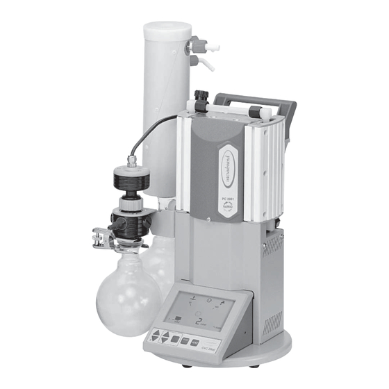
- Page 9 9 of 49 PC 2001 VARIO coolant outlet (hose nozzle 6 mm) outlet (gas!; hose nozzle 10 mm) coolant inlet (hose nozzle 6 mm) exhaust waste vapour condenser with cover handle pressure transducer VSK 5 gas ballast overpressure safety...
-
Page 10: Description
page 10 of 49 Description The controller can be adapted to the specific application by choosing another mode than ”Vacuum control” (factory-set), see section ”General view modes”. The status of the controller respectively of the connected accessories is displayed by corresponding symbols on the LCD. - Page 11 page 11 of 49 Keys • setting of frequency operating venting valve (only if • setting time for switch-off (only VACUU•LAN) valve is connected and prese- • switching (toggling) in modes lected) START VENT MODE STOP CVC 2000 • pressure setting (only vacuum control) start or stop of process control or •...
-
Page 12: Use And Operation
page 12 of 49 Use and operation Installing in a vacuum system: ☞ Avoid throttling losses by using connecting pipes with large diameter and keep them as short as possible. ☞ Reduce the transmission of vibration and prevent loading due to rigid pipelines. Insert elastic hoses or flexible elements as couplings between the pump and rigid pipes. - Page 13 page 13 of 49 ☞ The gas outlet (hose nozzle 10 mm) must not be blocked. The exhaust pipeline has always to be free and pressureless to enable an unhindered discharge of gases. ☞ Connect the exhaust to a suitable treatment plant to prevent the discharge of dan- gerous gases and vapours to the surrounding atmosphere.
- Page 14 page 14 of 49 During operation: Do not start or operate the pump if pressure at the outlet is higher than 1.1 bar absolute. Attempts to start or operate the pump at higher pressure may cause block- ade and damage of the motor. ☞...
- Page 15 page 15 of 49 In case of low boiling solvents when the formation of condensate is unlikely, the use of gas ballast might be unnecessary. ☞ Operating the pump without gas ballast increases the solvent recovery rates at the exhaust waste vapour condenser. Attention: Notes concerning the operation of the exhaust waste vapour condenser ➨...
-
Page 16: General View Modes
page 16 of 49 General view modes CVC 2000 setting pressure unit (mbar / Torr / hPa) setting mode mode ”vacuum control” (factory set) controller controls pump according to preset pressure value or in automatic mode coolant valve (optional) venting valve (optional) mode ”continuous pumping”... -
Page 17: How To Configurate The Controller
The vacuum controller CVC 2000 offers three modes depending on the components of the VACUUBRAND chemistry vacuum system which are con- nected to the system. the specific user and/or process requirements. In all modes: ☞... - Page 18 page 18 of 49 VACUU•LAN: ➨ The mode for decentralized vacuum network systems (for vacuum in laboratories, vacuum lines for weekend, night or trainee operations). Continuous vacuum without continuous pumping. ➨ The coolant is switched off if no more pumping is required, switched on again if gas or vapour occur.
- Page 19 page 19 of 49 If the automatic mode has been preselected “End” is displayed. ☞ Switching between automatic switching off activated or not activated is possible by pressing key ▲ or ▼. ➨ Confirm by pressing key START/STOP. ☞ The controller switches to normal operation mode (process control not active).
-
Page 20: General View Mode Vacuum Control
page 20 of 49 General view mode vacuum control selection of the mode mode vacuum control connect and switching coolant configurate valve? coolant valve connect and switching configurate venting venting valve valve? pre-set switching off automatic mode? at end process? set pressure for switching off or automatic switch-... -
Page 21: Mode Vacuum Control
page 21 of 49 Mode vacuum control After switching on The process control is not active, i. e. the controller is ready for vacuum control, but control operation has not been started. ☞ The mode as from last operation is reactivated (after first switching on “vacuum control”... - Page 22 page 22 of 49 Setting of set point p (e. g. boiling point) ➨ Setting the set point by using the keys p▲ or p▼ (factory set 100 mbar): ☞ To activate set mode: Press key shortly. “Set p“ appears. ☞...
- Page 23 page 23 of 49 Automatic mode Additional switching on the automatic mode ➨ Press key MODE. ☞ “Auto” is displayed. ☞ After starting process control, the pressure is adapted to MODE the process automatically: The controller determines the pres- sure and adapts if process parameters change. ☞...
- Page 24 page 24 of 49 Automatic switching off To chose a pressure value for automatic switching off is only possible if automatic switching off is activated (in mode vacuum control with automatic). ➨ Press key MODE simultaneous with ▼ (arrow down). MODE ☞...
-
Page 25: Mode Continuous Pumping
page 25 of 49 Mode continuous pumping After switching on The process control is not active, i. e. the controller is ready for vacuum control, but control operation has not been started. ☞ The mode as from last operation is reactivated (after first switching on “vacuum control”... - Page 26 page 26 of 49 Setting the pumping speed Setting of speed: Setting the value for the speed by using key Mode ▲ or ▼: ☞ To activate set mode: Press key shortly. The current speed 45.0 is displayed for one second. ☞...
-
Page 27: General View Mode Vacuu•Lan
page 27 of 49 General view mode VACUU•LAN setting the mode mode VACUU•LAN connect and switching coolant configurate valve? coolant valve switching connect and venting configurate valve? venting valve setting process parameters ➨ lower pressure value (condition for automatic shut down) ➨... -
Page 28: Mode Vacuu•Lan
page 28 of 49 Mode VACUU•LAN After switching on The process control is not active, i. e. the controller is ready for vacuum control, but control operation has not been started. ☞ The mode as from last operation is reactivated (after first switching on “vacuum control”... - Page 29 page 29 of 49 Setting the process parameter Setting the time for automatic shut down: ➨ Press key Mode ▲ or ▼. ☞ Set and the clock symbol and the time for automatic shut down are displayed for approx. 1 s. ☞...
-
Page 30: Accessories
page 30 of 49 Accessories Coolant minimization Coolant valve 24 V= ........... 676013 compact design, designed for a high number of operations at short intervals solenoid systems with splash protection conductance optimized for applications with rotary evapora- tor and exhaust waste vapour condenser Venting Venting valve VB M2 24 V= ........ -
Page 31: Troubleshooting
page 31 of 49 Troubleshooting ☞ ☞ ☞ ☞ ☞ Read the instructions for use. c t i d l i i t c . r i l i t i t c . r i f i r s t i e i l >... - Page 32 page 32 of 49 l l o c t i s l i o l l . y l l n i i t l e l l y l t t i s y l t n i l l n i , t r n i l...
-
Page 33: Readjustment
page 33 of 49 Readjustment The vacuum gauge was adjusted using factory standards, which are traceable through regular calibration in an accredited laboratory (German Calibration service) to the na- tional standard. Depending on the process and/or accuracy requirements, check the adjustment and readjust if necessary. -
Page 34: How To Determine The Best Distillation Conditions
page 34 of 49 How to determine the best distillation conditions Determine the temperature of the available coolant. ☞ In most cases the coolant temperature is given (e. g. tap water, in house coolant circuit). For maximum solvent recovery, carefully choose the boiling point of the product (by choosing the vacuum level) and the bath temperature accordingly. -
Page 35: Interface Parameters
page 35 of 49 Interface parameters The controller CVC 2000 is equipped with a serial interface at the rear side of the housing (RS 232C, nine- pole Sub-D-plug). ☞ Respectively plug-into or remove the cable (cable RS 232C, nine-pole, Sub-D) from the interface only if the equipment is switched off. -
Page 36: Read Commands
page 36 of 49 Read commands Function Command Response Description actual pressure IN_PV_1 XXXX mbar or unit according to preselections XXXX Torr or XXXX hPa actual frequency IN_PV_2 XX.X Hz device set IN_CFG XXXXX preselections 0: remote operation off 1: remote operation on 0: no automatic switch off 1: automatic switch off 0: no venting valve... -
Page 37: Write Commands
page 37 of 49 Write commands Function Command Parameter Description selected pressure OUT_SP_1 XXXX unit according to preselection (0001 to 1060 mbar (hPa) or 0001 to 0795 Torr) selected pressure OUT_SP_V XXXX unit according to preselection with venting* (0001 to 1060 mbar (hPa) or 0001 to 0795 Torr) selected frequency OUT_SP_2 XX.X... -
Page 38: Replacing Diaphragms And Valves
page 38 of 49 Replacing diaphragms and valves All bearings are encapsulated and are filled with long-life lubricant. Under normal oper- ating conditions, the pump is maintenance free. The valves and the diaphragms are wear parts. If the rated ultimate vacuum is no longer achieved or in case of increased noise level, the pump interior, the diaphragms and the valves must be cleaned and the diaphragms and valves must be checked for cracks or other damage. - Page 39 page 39 of 49 Use open-ended wrench to remove union nut at hose connec- tion next to the gas ballast. Use open ended wrench (w/f 15) to turn elbow fitting 1/4 of a turn, reconnect hose. Do not remove the elbow fitting from the pump head.
- Page 40 page 40 of 49 View of the disassembled pump head parts bearing plate housing diaphragm support disc valve diaphragm head cover housing cover diaphragm clamping disc with connecting screw Documents are only to be used and distributed completely and unchanged. It is strictly the users´ responsibility to check carefully the validity of this document with respect to his product.
- Page 41 page 41 of 49 Position new diaphragm between diaphragm clamping disc with square head screw and diaphragm support disc. ☞ Note: Position diaphragm with light-coloured PTFE side to diaphragm clamping disc (to pump chamber). Lift diaphragm at the side and position carefully together with diaphragm clamping disc and diaphragm support disc in the diaphragm key.
- Page 42 page 42 of 49 Comply with position and orientation of the head covers and the valves definitely. scheme of pump head with head covers and valves ”side with hose connection” valves at the inlet (kidney-shaped opening beside valve) valves at the outlet (round centred ”motor side”...
- Page 43 page 43 of 49 Assembling of fittings: Use open ended wrench to reconnect hose to elbow fitting. Tighten union nuts first by hand and then tighten one full turn using open ended wrench. Connect hose to fitting. Tighten union nuts first by hand and then tighten one full turn using open ended wrench.
-
Page 44: Cleaning And Assembling Components
page 44 of 49 Cleaning and assembling components Overpressure safety relief device ......638821 (at the exhaust waste vapour condenser) ☞ Remove union nut at the condenser and remove hose from the inlet of the condenser. ☞ Unscrew the exhaust waste vapour condenser from the pumping unit. -
Page 45: Calibration In The Factory
Calibration in the factory Control of measuring equipment The VACUUBRAND DKD calibration laboratory is accredited by the Physikalisch-Technische Bundesanstalt (PTB; German national institute for science and technology and the highest technical authority of the Federal Republic of Germany for the field of meteorology and certain sectors of safety engineering) for the... -
Page 46: Notes On Return To The Factory
page 46 of 49 Notes on return to the factory Repair - return - DKD calibration Safety and health of our staff, laws and regulations regarding the handling of danger- ous goods, occupational health and safety regulations and regulations regarding safe disposal of waste require that for all pumps and other products the “Health and safety clearance form“... -
Page 47: Health And Safety Clearance Form
Tel.: +49 9342 808-0 - Fax: +49 9342 808-450 -Technology for Vacuum Systems- E-Mail: info@vacuubrand.de © 2003 VACUUBRAND GMBH + CO KG Printed in Germany Web: www.vacuubrand.com Documents are only to be used and distributed completely and unchanged. It is strictly the users´ responsibility to check... - Page 48 (Dr. F. Gitmans) (Dr. J. Dirscherl) Geschäftsführer / Managing director / Gérant Technischer Leiter / Technical Director / Directeur technique VACUUBRAND GMBH + CO KG Alfred-Zippe-Str. 4 - 97877 Wertheim -Vakuumtechnik im System- Tel.: +49 9342 808-0 - Fax: +49 9342 808-450 -Technology for Vacuum Systems- E-Mail: info@vacuubrand.de...
- Page 49 Tel.: +49 9342 808-0 - Fax: +49 9342 808-450 -Technology for Vacuum Systems- E-Mail: info@vacuubrand.de © 2008 VACUUBRAND GMBH + CO KG Printed in Germany Web: www.vacuubrand.de Documents are only to be used and distributed completely and unchanged. It is strictly the users´ responsibility to check...
Need help?
Do you have a question about the PC 2001 Vario and is the answer not in the manual?
Questions and answers