Table of Contents
Advertisement
Documents are only to be used and distributed completely and unchanged. It is strictly the users´ responsibility to check
carefully the validity of this document with respect to his product. Manual-no.: 999084 / 05/10/2009
page 1 of 46
Technology for Vacuum Systems
Instructions for use
PC 500 LAN
PC 600 LAN
Chemistry pumping units
Advertisement
Table of Contents

Related Manuals for vacuubrand PC 500 LAN


Summary of Contents for vacuubrand PC 500 LAN
- Page 1 1 of 46 Technology for Vacuum Systems Instructions for use PC 500 LAN PC 600 LAN Chemistry pumping units Documents are only to be used and distributed completely and unchanged. It is strictly the users´ responsibility to check carefully the validity of this document with respect to his product. Manual-no.: 999084 / 05/10/2009...
- Page 2 2 of 46 Dear customer, Your VACUUBRAND diaphragm pumps should support you for a long time without trouble and with maximal power. Thanks to our long practical experience we have much information how you could ensure powerful application and personal safety. Please read these instructions for use before the initial operation of your pump.
-
Page 3: Table Of Contents
page 3 of 46 Contents Safety information! ....................4 Technical data ......................8 Use and operation ....................12 Description ......................16 Notes on operation ....................18 General view of factory-set modes ................. 19 Menu structure of controller ................... 20 Working with the controller ..................22 Readjustment ...................... -
Page 4: Safety Information
page 4 of 46 Safety information! Remove all packing material, remove the product from its packing-box, remove the protective covers from the inlet and outlet ports and keep, inspect the equipment and check oil level. If the equipment is damaged, notify the supplier and the carrier in writing within three days;... - Page 5 page 5 of 46 Permissible maximum pressure at the pressure transducer: 1.5 bar (absolute). ☞ At pressures higher than 1060 mbar the display flashes. Error message ”p Er- ror” appears, four beeps. ➨ Immediate pressure relief necessary! Risk of bursting! Attention: At pressures above 1100 mbar the device does no longer display the cor- rect pressure values (pressure transducer saturated).
- Page 6 page 6 of 46 In case of overload the motor is shut down by a thermal cutout in the winding. ☞ Attention: Manual reset is necessary. Switch off the pump or isolate the equipment from mains. Wait approx. five minutes before restarting the pump ☞...
- Page 7 page 7 of 46 Wear parts have to be replaced regularly. In case of normal wear the lifetime of the diaphragms and valves is > 10000 operating hours. Bearings have a typical durability of 40000 h. Motor capacitors have a typical durability in the range of 10000 to 40000 h depending strongly on the operation conditions like ambient temperature, humidity or load.
-
Page 8: Technical Data
page 8 of 46 Technical data i t l i t l a l l a l l ° ° y t i v i t t t i n i l Pumping speed of diaphragm pump We reserve the right for technical modification without prior note! Gas inlet temperatures: ➨... - Page 9 page 9 of 46 v i t c t i ) r r ) r r y l l < ) r r b i l c i f < / r r ° 0 ° 0 ° 0 ° 0 v i t c t i n i l...
- Page 10 page 10 of 46 t t i i l e c i l e l l c i l c i l y l l We reserve the right for technical modification without prior note! Documents are only to be used and distributed completely and unchanged. It is strictly the users´ responsibility to check carefully the validity of this document with respect to his product.
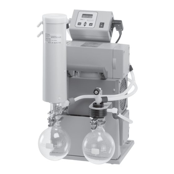
- Page 11 11 of 46 PC 500 LAN controller VNC 1 vacuum connection VNC 1 on/off switch controller connection exhaust waste vapour pump condenser with cover mains connection overpressure safety relief VNC 1 device at the exhaust fuse waste vapour condenser...
-
Page 12: Use And Operation
page 12 of 46 Use and operation Assembly of enclosed components Round bottom flasks: overpressure The catchpot at the inlet prevents droplets and particles from safety relief entering the pump. device ☞ Lifetimes of diaphragms and valves are enhanced. catchpot at ☞... - Page 13 page 13 of 46 Prior to use: ☞ Maximum ambient temperature: 30 °C or 40 °C (See ”Technical Data - VNC 1”). ☞ Make sure ventilation is adequate if pump is installed in a housing or if ambient temperature is elevated. Keep a distance of minimum 20 cm between fans and ambient parts.
- Page 14 page 14 of 46 Attention: Important notes regarding the use of gas ballast ☞ Make sure that air/gas inlet through the gas ballast valve never lead to hazardous, explosive or otherwise dangerous mixtures. If in doubt, use inert gas. ☞ When using air rather than inert gas, risk of significant damage to equipment and/or facilities, risk of personal injury or even loss of life exists due to the formation of hazardous and/or explosive mixtures if air and pumped media react inside or at the outlet of the pump.
- Page 15 page 15 of 46 Catchpot at inlet: ➨ Admit air or inert gas (via inlet of pumping unit) to atmospheric pressure. Remove joint clip, remove catchpot and drain condensate. ➨ Reassemble drained catchpots. Important: Comply with regulations when disposing solvents/condensates. Reuse if possible, purify if contaminated.
-
Page 16: Description
page 16 of 46 Description After the connection of components the controller can be operated in different basic modes, see ”Basic modes and menu structure”. When switching on the controller, the current basic mode and the number of version are displayed for 2s. Display and keys Display In menus... - Page 17 page 17 of 46 Connections 8-pin socket for connection of coolant valve or isolation valve vacuum connection or speed control signal (PWM) serial interface RS 232 C connection of pump or of valve according to power supply (switch output) cover fuse switch output connection mains cable Documents are only to be used and distributed completely and unchanged.
-
Page 18: Notes On Operation
page 18 of 46 Assignment of pins coolant valve + 24V isolation valve external error - external error + mass (PWM -) PWM + (speed control signal for VARIO pumps) +12 V Notes on operation For operation it is necessary to install valves and/or vacuum pumps. Note: Texts written in Courier font mirror the display of the LCD of the controller. -
Page 19: General View Of Factory-Set Modes
* only with speed controlled VACUUBRAND VARIO pumps VACUULAN ** designated for VACUUBRAND diaphragm pumps type ME 16(C), MD 8(C), V. 2.00 MD 12(C) und MV 10(C) Attention: When connecting pumps pay attention to the breaking capacity of the IEC socket (see ”Technical Data”)! -
Page 20: Menu Structure Of Controller
page 20 of 46 Menu structure of controller after 2 sec 1013mbar VACUULAN ↵ ↵ ↵ ↵ ↵ Switch on Start V. 2.00 within within 2 sec 2 sec ↵ ↵ ↵ ↵ ↵ Function menu Device menu Program menu see next page Function •... - Page 21 page 21 of 46 Documents are only to be used and distributed completely and unchanged. It is strictly the users´ responsibility to check carefully the validity of this document with respect to his product. Manual-no.: 999084 / 05/10/2009...
-
Page 22: Working With The Controller
page 22 of 46 Working with the controller Notes on selecting the basic mode The controller VNC 1 can be adapted to the specific application by choosing the appro- priate mode, VACUU•LAN, continuous pumping, vacuum control, pressure check or RC 5/RC 6 management. The components of the chemistry vacuum system (e.g. ”Valve”, ”VARIO”) have to be preset once only. - Page 23 page 23 of 46 Program menu in mode VACUULAN and VCL 8cyl 1013mbar Start VACUULAN VACUULAN VACUULAN VACUULAN t Off p Set p On tProcess ↵ ↵ ↵ ↵ ↵ ↵ ↵ ↵ ↵ ↵ ↵ ↵ ↵ ↵ ↵ ↵...
- Page 24 page 24 of 46 Manually controlled vacuum applications: In general: Avoid parallel processes which differ strongly in their demands concerning pumping speed or ultimate vacuum as well as their simultaneous operation. If several manually controlled ports are operated simultaneously, it is recommended to install a flow control, such that the required process pressures of the applications are just attained.
-
Page 25: Readjustment
page 25 of 46 Readjustment The vacuum gauge was adjusted using factory standards, which are traceable through regular calibration in an accredited laboratory (German Calibration service) to the na- tional standard. Depending on the process and/or accuracy requirements, check the adjustment from time to time and readjust if necessary. -
Page 26: Interface Parameters
page 26 of 46 Interface parameters The controller VNC 1 is equipped with a serial interface (RS 232C, nine-pole Sub-D-plug). ☞ Respectively plug-into or remove the cable (cable RS 232C, nine-pole Sub-D) from the interface only if the equipment is switched off. ☞... -
Page 27: Read Commands
page 27 of 46 Read commands Function Command Response Description Actual pressure IN_PV_1 XXXX mbar or Unit according to preselection XXXX Torr or XXXX hPa Actual pumping speed IN_PV_2 XX.X Hz Time IN_PV_3 XX:XX h:m Time for shut down or time of warmup (only RC 5/RC 6) Increase of pressure IN_PV_4... - Page 28 page 28 of 46 Read commands Function Command Response Description Error status IN_ERR XXXX 1: Last command to interface incorrect 1: Failure at pressure transducer 1: Overpressure 1: See ERR_1 Error status IN_ERR_1 XXXX 1: Temperature error 1: Error isolation valve 1: Error coolant valve 1: External errorr (e.g.
-
Page 29: Write Commands
page 29 of 46 Read command Function Command Response Description Status of IN_STAT_1 XXXXX process control Mode : see IN_STAT Status of operation : see IN_STAT Isolation valve 0: closed 1: open Cooling water 0: closed valve 1: open Relay 0: not operated 1: operated Write commands... - Page 30 page 30 of 46 Write commands Function Command Parameter Description Configuration OUT_CFG XXXXXXX 0: Remote off 1: Remote on 0: Unit of pressure mbar 1: Unit of pressure Torr 2: Unit of pressure hPa 0: External error off 1: External error on (evaluation) 2: Stop (control is stopped) 0: Acoustic signal not configured 1: Acoustic signal configured...
-
Page 31: Installation And Accessories
page 31 of 46 Installation and accessories Vacuum distribution The VACUU•LAN ® modules allow process orientated, flexible and cost effective connections according to the requirements: VCL 11 One vacuum pump for multiple work stations. VCL 02 ® VACUU•LAN manual flow control module VCL 01 ................ -
Page 32: Troubleshooting
page 32 of 46 Troubleshooting c t i d l i v i t d l i c t i l l o v i t . r i e l l l i t v i t e l l l l o v i t . - Page 33 page 33 of 46 o l l s l i . y l u l i n i l n i l o l l y f i l i a y l t i t l t i s y l t n i l l n i...
-
Page 34: How To Determine The Best Distillation Conditions
page 34 of 46 How to determine the best distillation conditions Determine the temperature of the available coolant. ☞ In most cases the coolant temperature is given (e. g. tap water, in house cooling water circuit). For maximum solvent recovery, carefully choose the boiling point of the product (by choosing the vacuum level) and the bath temperature accordingly. -
Page 35: Replacing Diaphragms And Valves
page 35 of 46 Replacing diaphragms and valves All bearings are encapsulated and are filled with long-life lubricant. Under normal oper- ating conditions, the pump is maintenance free. The valves and the diaphragms as well as the motor capacitors are wear parts. If the rated ultimate vacuum is no longer achieved or in case of increased noise level, the pump interior, the diaphragms and the valves must be cleaned and the diaphragms and valves must be checked for cracks or other damage. - Page 36 page 36 of 46 Disassembling the pump from the pump support ➨ Use open-ended wrench (w/f 17) to remove union nut on the fitting of the cover plate. ➨ Use open-ended wrench (w/f 14) to turn elbow fitting 1/4 of a turn, remove hose.
- Page 37 page 37 of 46 ➨ Use open-ended wrench (w/f 14) to turn elbow fitting 1/4 of a turn, remove hose. ☞ Do not remove the elbow fitting from the pump head. Through reassembly a leak may result. ➨ To check valves use hex key to remove four socket head screws from pump head and remove upper housing (hous- ing cover with housing cover insert), head cover and valves.
- Page 38 Optimum torque for the diaphragm support disc: 6 Nm. ☞ The optimum torque is achieved if the pointer in the handle of the VACUUBRAND face wrench shows to the longer mark- ing line. position 2: indicator should point here when the optimal torque is reached position 1: resting position Documents are only to be used and distributed completely and unchanged.
- Page 39 page 39 of 46 Assembling pump heads ➨ By turning eccentric bushing (front of connecting rod), bring connecting rod into a position in which diaphragm is in con- tact with housing and centred with respect to bore. Reassemble in reverse order. ➨...
- Page 40 page 40 of 46 ➨ Tighten union nuts first by hand and then tighten one full turn using open ended wrench (w/f 17). If the pump does not achieve the ultimate pressure: ☞ In case the diaphragms and valves have been replaced, a run-in period of several hours is required before the pump achieves its ultimate vacuum.
-
Page 41: Cleaning The Pressure Transducer
page 41 of 46 ➨ Tighten union nut first by hand and then tighten by one full turn using open-ended wrench. Cleaning and assembling components Overpressure safety relief device ......638821 (at the exhaust waste vapour condenser) ☞ Remove union nut at the condenser and remove hose from the inlet of the condenser. -
Page 42: Calibration In The Factory
Calibration in the factory Control of measuring equipment The VACUUBRAND DKD calibration laboratory is accredited by the Physikalisch-Technische Bundesanstalt (PTB; German national institute for science and technology and the highest technical authority of the Federal Republic of Germany for the field of meteorology and certain sectors of safety engineering) for the... -
Page 43: Notes On Return To The Factory
page 43 of 46 Notes on return to the factory Repair - return - DKD calibration Safety and health of our staff, laws and regulations regarding the handling of danger- ous goods, occupational health and safety regulations and regulations regarding safe disposal of waste require that for all pumps and other products the “Health and safety clearance form“... -
Page 44: Health And Safety Clearance Form
Tel.: +49 9342 808-0 - Fax: +49 9342 808-450 -Technology for Vacuum Systems- E-Mail: info@vacuubrand.de © 2001 VACUUBRAND GMBH + CO KG Printed in Germany Web: www.vacuubrand.com Documents are only to be used and distributed completely and unchanged. It is strictly the users´ responsibility to check... - Page 45 Déclaration de conformité Chemie-Pumpstand / Chemistry pumping unit / Groupe de pompage chimique PC 500 LAN (230 V; 688140, 688141, 688142) PC 600 LAN (230 V; 688160, 688161, 688162) Hiermit erklären wir, dass das oben bezeichnete Gerät in Konzeption und Bauart sowie in der von uns in Verkehr gebrachten Ausführung den grundlegenden Anforderungen der zutreffenden, aufgeführten EU-...
- Page 46 E-Mail: info@vacuubrand.de Web: www.vacuubrand.com © 2009 VACUUBRAND GMBH + CO KG Printed in Germany Documents are only to be used and distributed completely and unchanged. It is strictly the users´ responsibility to check carefully the validity of this document with respect to his product. Manual-no.: 999084 / 05/10/2009...
Need help?
Do you have a question about the PC 500 LAN and is the answer not in the manual?
Questions and answers