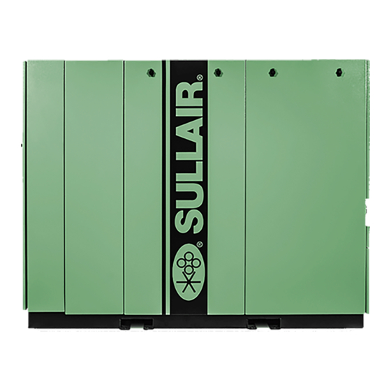
Sullair SN55 User Manual

Sullair SN55 User Manual

Industrial air compressor
Table of Contents

Advertisement

Industrial Air Compressor
SAFETY WARNING
Users are required to read the
entire User Manual before han-
dling or using the product. Keep
the User Manual in a safe place
for future reference.
USER MANUAL
SN55, SN55S, SN55V,
SN75, SN75S, SN75V
75 & 100 hp (55 & 75 kW)
WARRANTY NOTICE
Failure to follow the instructions
and procedures in this manual,
or misuse of this equipment, will
void its warranty.
Subject to EAR, ECCN EAR99 and related export control restrictions.
PART NUMBER:
02250247-571 R04
The information in this manual is current as of its
publication date and applies to compressor models
indicated on this cover with serial number:
201903080000
and all subsequent serial numbers until next revision of
this manual or release of a replacement manual..
Publication date: 03/27/2020
Copyright © 2020 Sullair, LLC. All rights reserved.

Advertisement

Table of Contents
loading

Summary of Contents for Sullair SN55

  • Page 1 User Manual in a safe place void its warranty. Publication date: 03/27/2020 for future reference. Copyright © 2020 Sullair, LLC. All rights reserved. Subject to EAR, ECCN EAR99 and related export control restrictions.
  • Page 2 Sullair training courses provide hands-on and classroom instruction for the proper operation, maintenance, and servicing of Sullair products. Individual courses on Stationary compressors, variable speed drives, compressor electrical systems, and dryers are offered at regular intervals throughout the year at Sullair’s training facility located in Michigan City, Indiana.
  • Page 3: Table Of Contents

    SN55, SN55S, SN55V, SN75, SN75S, SN75V User Manual Table of Contents Table of Contents Section 1: Safety.......................6 General............................6 Personal protective equipment ......................6 Pressure release ..........................6 Fire and explosion ........................... 7 Moving parts ............................ 7 Hot surfaces, sharp edges and sharp corners................. 8 Toxic and irritating substances ......................
  • Page 4 Table of Contents SN55, SN55S, SN55V, SN75, SN75S, SN75V User Manual 3.12 Piping & instrumentation, air-cooled—SN55S, SN75S ..............39 3.13 Piping & instrumentation, water-cooled—SN55S, SN75S ............41 3.14 Piping & instrumentation, air-cooled—SN55V, SN75V ..............43 3.15 Piping & instrumentation, water-cooled—SN55V, SN75V ............45 3.16 Wiring diagram, wye-delta......................
  • Page 5 SN55, SN55S, SN55V, SN75, SN75S, SN75V User Manual Table of Contents Separator maintenance ......................... 72 6.7.1 Separator element replacement..................72 Oil return / sight glass maintenance ....................73 Pressure regulator adjustment ...................... 73 6.10 Water condensate drain maintenance................... 74 6.11 Control line strainer ........................74 6.12 Shaft coupling maintenance ......................
  • Page 6 Table of Contents SN55, SN55S, SN55V, SN75, SN75S, SN75V User Manual Notes: 02250247-571 R04 Subject to EAR, ECCN EAR99 and related export control restrictions.
  • Page 7: Section 1: Safety

    SN55, SN55S, SN55V, SN75, SN75S, SN75V User Manual 1: Safety Section 1 Safety most compressors and the concepts behind these state- NOTE ments are generally applicable to all compressors. 1.2 Personal protective equipment A. Prior to installing or operating the compressor, own-...
  • Page 8: Fire And Explosion

    1: Safety SN55, SN55S, SN55V, SN75, SN75S, SN75V User Manual accordance with their manufacturer's recommenda- material. Any acoustical material with a protective tions. covering that has been torn or punctured should be replaced immediately to prevent accumulation of liq- E. DO NOT use air tools that are rated below the maxi- uids or fluid film within the material.
  • Page 9: Hot Surfaces, Sharp Edges And Sharp Corners

    SN55, SN55S, SN55V, SN75, SN75S, SN75V User Manual 1: Safety E. Make sure all personnel are out of and/or clear of the B. DO NOT use air line anti-icer systems in air lines compressor prior to attempting to start or operate it.
  • Page 10: Lifting

    1: Safety SN55, SN55S, SN55V, SN75, SN75S, SN75V User Manual ments or repairs to exposed live parts of the electrical D. Make sure lifting hook has a functional safety latch or system. Make all such adjustments or repairs with equivalent, and is fully engaged and latched on the one hand only, so as to minimize the possibility of bail or slings.
  • Page 11: Implementation Of Lockout/Tagout

    SN55, SN55S, SN55V, SN75, SN75S, SN75V User Manual 1: Safety person shall be provided with their own padlock 1.11 Implementation of lockout/tagout and have possession of the only key. If more The energy control procedure defines actions necessary than one person is working on a machine each...
  • Page 12: Safety Warnings

    1: Safety SN55, SN55S, SN55V, SN75, SN75S, SN75V User Manual 1.12 Safety warnings WARNING The following special instructions apply to VSD packages provided with electronic adjustable speed motor drives. These cautions that apply to VSD operation. Before opening the variable speed drive covers: •...
  • Page 13: Safety Decals

    SN55, SN55S, SN55V, SN75, SN75S, SN75V User Manual 1: Safety NOTE CAUTION Customer must provide electrical supply power Install the variable speed drive in a well venti- disconnect within sight of machine. lated room that is not subject to temperature...
  • Page 14 1: Safety SN55, SN55S, SN55V, SN75, SN75S, SN75V User Manual Notes: 02250247-571 R04 Subject to EAR, ECCN EAR99 and related export control restrictions.
  • Page 15: Section 2: Description

    SN55, SN55S, SN55V, SN75, SN75S, SN75V User Manual 2: Description Section 2 Description cated- type compressor. This unit provides continuous 2.1 Introduction compression to meet your needs. Your new Sullair flood-lubricated rotary screw air com- pressor will provide you with a unique experience in NOTE improved reliability and simplified maintenance.
  • Page 16 2: Description SN55, SN55S, SN55V, SN75, SN75S, SN75V User Manual 1. Compressor unit 8. Moisture separator 2. Motor 9. Fluid filter 3. Cooler fan motor 10. Fluid fill 4. Electrical enclosure 11. Fluid fill sight glass 5. E-stop button 12. Separator/sump tank 6.
  • Page 17 SN55, SN55S, SN55V, SN75, SN75S, SN75V User Manual 2: Description 1. Compressor unit 8. Moisture separator 2. Motor 9. Fluid filter 3. Oil cooler 10. Fluid fill 4. Electrical enclosure 11. Fluid fill sight glass 5. E-stop button 12. Separator/sump tank 6.
  • Page 18: Compressor Cooling And Lubrication System, Functional Description

    2: Description SN55, SN55S, SN55V, SN75, SN75S, SN75V User Manual The fractional percentage of fluid remaining in the com- 2.4 Compressor cooling and lubrication pressed air collects on the surface of the separator ele- system, functional description ment as the compressed air flows through the separator.
  • Page 19 SN55, SN55S, SN55V, SN75, SN75S, SN75V User Manual 2: Description 1. Compressor unit 4. Moisture separator 2. Separator/sump tank 5. Cooler 3. Fluid filter Figure 2-3: Air-cooled, cooling / lubrication and discharge system 02250247-571 R04 Subject to EAR, ECCN EAR99 and related export control restrictions.
  • Page 20 2: Description SN55, SN55S, SN55V, SN75, SN75S, SN75V User Manual 1. Compressor unit 4. Moisture separator 2. Separator/sump tank 5. Oil cooler 3. Fluid filter 6. Aftercooler Figure 2-4: Water-cooled, cooling / lubrication and discharge system 02250247-571 R04 Subject to EAR, ECCN EAR99 and related export control restrictions.
  • Page 21 SN55, SN55S, SN55V, SN75, SN75S, SN75V User Manual 2: Description and an inlet valve. The functional description of the control bypass ports gradually. Excess air is then being returned system is described below in four distinct phases of opera- back internally to the suction end of the compressor unit.
  • Page 22 2: Description SN55, SN55S, SN55V, SN75, SN75S, SN75V User Manual compressor to shutdown (time delayed) when no compressed air Automatic operation requirement is present and restart as compressed air is needed. For applications with varied periods of time when there are no air requirements, the controller’s AUTOMATIC mode allows the...
  • Page 23 SN55, SN55S, SN55V, SN75, SN75S, SN75V User Manual 2: Description 1. Air inlet 5. Air outlet 2. Minimum pressure/check valve 6. Pressure regulator 3. Blowdown valve 7. Sequencing solenoid valve 4. Separator/sump tank 8. Unload solenoid valve Figure 2-5: Standard pneumatic control system 02250247-571 R04 Subject to EAR, ECCN EAR99 and related export control restrictions.
  • Page 24: Air Inlet System, Functional Description

    2: Description SN55, SN55S, SN55V, SN75, SN75S, SN75V User Manual 2.7 Air inlet system, functional description WARNING Refer to Figure 2-6. The compressor inlet system con- sists of a dry-type air filter, a restriction gauge and an air “The Plastic Pipe Institute recommends against inlet valve.
  • Page 25: Variable Speed Drive (Vsd) Components

    SN55, SN55S, SN55V, SN75, SN75S, SN75V User Manual 2: Description and the air-end provides a full flow to the separator/sump 2.8 Variable speed drive (VSD) tank. A minimum pressure valve set at approximately components 50 psig (3.4 bar) isolates the rising compressor air pres- The VSD, located in the machine’s electrical enclosure,...
  • Page 26 2: Description SN55, SN55S, SN55V, SN75, SN75S, SN75V User Manual Notes: 02250247-571 R04 Subject to EAR, ECCN EAR99 and related export control restrictions.
  • Page 27: Section 3: Specifications

    SN55, SN55S, SN55V, SN75, SN75S, SN75V User Manual 3: Specifications Section 3 Specifications 3.1 Table of specifications—SN55, SN55S, SN75, SN75S Dimensions Length Width Height Weight Power TEFC Model SN55 series 5507 87.6 2225 43.4 1103 68.5 1740 3313 1505 5509 87.6...
  • Page 28: Table Of Specifications-Sn55V, Sn75V

    3: Specifications SN55, SN55S, SN55V, SN75, SN75S, SN75V User Manual 3.2 Table of specifications—SN55V, SN75V Dimensions Length Width Height Weight Drive amp Motor voltage /Hz rating VSD series—SN55V (models 5507V through 5512V) 460/60 87.6 2225 43.4 1103 68.5 1740 3411...
  • Page 29: Compressor Specifications

    SN55, SN55S, SN55V, SN75, SN75S, SN75V User Manual 3: Specifications 3.3 Compressor specifications Compressor Standard models Type Rotary screw Standard operating pressure 100 psig (7 bar) 125 psig (9 bar) Bearing type Anti-friction Maximum ambient temperature 104°F (40°C) Minimum ambient temperature 40°F (4.4°C)
  • Page 30: Application Guide

    Sul- lair for recommendation. 3.6 Application guide Sullair encourages the user to participate in a fluid analy- sis program with the fluid suppliers. This could result in a fluid change interval differing from that stated in the man- ual.
  • Page 31: Lubrication Change Recommendations And Maintenance, Fluid

    SN55, SN55S, SN55V, SN75, SN75S, SN75V User Manual 3: Specifications 3.7 Lubrication change recommendations and maintenance, fluid Lubricant Fluid change Fluid filter change Separator change ® Sullube (7.2 gal / 27.3 L) G, C I, D PristineFG™ (7.2 gal / 27.3 L)
  • Page 32: Identification, Air-Cooled

    3.8 Identification, air-cooled 02250242-484 R02...
  • Page 33 3.8 Identification, air-cooled Drawing notes ALLOW 1.25 METERS [4.00 FEET] MINIMUM CLEARANCE AROUND MACHINE FOR ACCESS AND FREE CIRCULATION OF AIR. A FOUNDATION OR MOUNTING CAPABLE OF SUPPORTING THE WEIGHT OF PACKAGE, AND RIGID ENOUGH TO MAINTAIN THE COMPRESSOR FRAME LEVEL IS REQUIRED. THE COMPRESSOR FRAME MUST BE LEVELLED AND SECURED BETWEEN THE FRAME AND THE FOUNDATION. NO PIPING LOADS ARE PERMITTED AT EXTERNAL CONNECTIONS.
  • Page 34: Identification, Water-Cooled

    3.9 Identification, water-cooled 02250242-503 R02...
  • Page 35 3.9 Identification, water-cooled Drawing notes ALLOW 1.25 METERS [4.00 FEET] MINIMUM CLEARANCE AROUND MACHINE FOR ACCESS AND FREE CIRCULATION OF AIR. A FOUNDATION OR MOUNTING CAPABLE OF SUPPORTING THE WEIGHT OF PACKAGE, AND RIGID ENOUGH TO MAINTAIN THE COMPRESSOR FRAME LEVEL IS REQUIRED. THE COMPRESSOR FRAME MUST BE LEVELLED AND SECURED BETWEEN THE FRAME AND THE FOUNDATION. NO PIPING LOADS ARE PERMITTED AT EXTERNAL CONNECTIONS.
  • Page 36: Piping & Instrumentation, Air-Cooled-Sn55, Sn75

    3.10 Piping & instrumentation, air-cooled—SN55, SN75 02250218-394 R02...
  • Page 37 3.10 Piping & instrumentation, air-cooled—SN55, SN75 Key Description Key Description FILTER,AIR Drawing notes INDICATOR, RESTRICTION CONTROL/MOISTURE DRAIN LINES ARE 1/4" TUBING EXCEPT AS NOTED. VALVE,INLET OPTIONAL HEAT TRACE IS APPLIED ONLY TO CONTROL AND COMPRESSOR UNIT MOISTURE DRAIN LINES AND USED ONLY WITH STAINLESS STEEL TUBING.
  • Page 38: Piping & Instrumentation, Water-Cooled-Sn55, Sn75

    3.11 Piping & instrumentation, water-cooled—SN55, SN75 02250218-395 R03...
  • Page 39 3.11 Piping & instrumentation, water-cooled—SN55, SN75 Key Description Key Description FILTER, AIR DRAIN,ZERO LOSS INDICATOR, RESTRICTION Drawing notes VALVE,INLET CONTROL/MOISTURE DRAIN LINES ARE 1/4" TUBING EXCEPT AS NOTED. COMPRESSOR UNIT OPTIONAL HEAT TRACE IS APPLIED ONLY TO CONTROL AND MOTOR MOISTURE DRAIN LINES AND USED ONLY WITH STAINLESS STEEL TUBING.
  • Page 40: Piping & Instrumentation, Air-Cooled-Sn55S, Sn75S

    3.12 Piping & instrumentation, air-cooled—SN55S, SN75S 02250243-744 R00...
  • Page 41 3.12 Piping & instrumentation, air-cooled—SN55S, SN75S Key Description Key Description FILTER,AIR OPTIONAL HEAT TRACE IS APPLIED ONLY TO CONTROL AND MOISTURE DRAIN LINES AND USED ONLY WITH STAINLESS INDICATOR,RESTRICTION STEEL TUBING. REFER TO FACE OF ORDER FOR HEAT TRACE REQUIREMENTS. VALVE,INLET COMPRESSOR Component...
  • Page 42: Piping & Instrumentation, Water-Cooled-Sn55S, Sn75S

    3.13 Piping & instrumentation, water-cooled—SN55S, SN75S 02250243-745 R00...
  • Page 43 3.13 Piping & instrumentation, water-cooled—SN55S, SN75S Key Description Key Description FILTER, AIR Drawing notes INDICATOR, RESTRICTION CONTROL/MOISTURE DRAIN LINES ARE 1/4" TUBING EXCEPT AS NOTED. VALVE, INLET OPTIONAL HEAT TRACE IS APPLIED ONLY TO CONTROL AND COMPRESSOR MOISTURE DRAIN LINES AND USED ONLY WITH STAINLESS STEEL TUBING.
  • Page 44: Piping & Instrumentation, Air-Cooled-Sn55V, Sn75V

    3.14 Piping & instrumentation, air-cooled—SN55V, SN75V 02250243-740 R00...
  • Page 45 3.14 Piping & instrumentation, air-cooled—SN55V, SN75V Key Description Key Description FILTER, AIR OPTIONAL HEAT TRACE IS APPLIED ONLY TO CONTROL AND MOISTURE DRAIN LINES AND USED ONLY WITH STAINLESS INDICATOR, RESTRICTION STEEL TUBING. REFER TO FACE OF ORDER FOR HEAT TRACE REQUIREMENTS.
  • Page 46: Piping & Instrumentation, Water-Cooled-Sn55V, Sn75V

    3.15 Piping & instrumentation, water-cooled—SN55V, SN75V 02250243-741 R00...
  • Page 47 3.15 Piping & instrumentation, water-cooled—SN55V, SN75V Key Description Key Description FILTER, AIR CONTROL/MOISTURE DRAIN LINES ARE 1/4" TUBING EXCEPT AS NOTED. INDICATOR, RESTRICTION OPTIONAL HEAT TRACE IS APPLIED ONLY TO CONTROL AND VALVE, INLET MOISTURE DRAIN LINES AND USED ONLY WITH STAINLESS STEEL TUBING.
  • Page 48: Wiring Diagram, Wye-Delta

    3.16 Wiring diagram, wye-delta 02250242-364 R04 (sh1)
  • Page 49 3.16 Wiring diagram, wye-delta 02250242-364 R04 (sh2)
  • Page 50 Drawing notes CUSTOMER TO FURNISH FUSED OR CIRCUIT BREAKER DISCONNECT PER LOCAL CODES. REMOVE JUMPER FOR AUXILLIARY E-STOP STRING DEVICES. BELDEN TYPE 9842 4 CONDUCTOR 2 TWISTED PAIR WITH SHIELD OR EQUIVALENT TO MATCHING TERMINALS ON NEXT COMPRESSOR FOR SEQUENCING. SEE TRANSFORMER CONNECTION TABLE FOR PROPER VOLTAGE CONNECTION.
  • Page 51 Notes:...
  • Page 52: Wiring Diagram, Vsd Air-Cooled Parallel Wye

    3.17 Wiring diagram, VSD air-cooled parallel wye 02250243-116 R05 (sh1)
  • Page 53 3.17 Wiring diagram, VSD air-cooled parallel wye 02250243-116 R05 (sh2)
  • Page 54 3.17 Wiring diagram, VSD air-cooled parallel wye Drawing notes CUSTOMER TO FURNISH FUSED OR CIRCUIT BREAKER DISCONNECT PER LOCAL CODES. REMOVE JUMPER FOR AUXILLIARY E-STOP STRING DEVICES. BELDEN TYPE 9842 4 CONDUCTOR 2 TWISTED PAIR WITH SHIELD OR EQUIVALENT TO MATCHING TERMINALS ON NEXT COMPRESSOR FOR SEQUENCING.
  • Page 55: Section 4: Installation

    SN55, SN55S, SN55V, SN75, SN75S, SN75V User Manual 4: Installation Section 4 Installation require a minimum of 4 feet (1.25 meters) around the 4.1 Mounting of compressor perimeter of the compressor. A suitable foundation or fabricated support must be established to support the compressor. It should be rigid...
  • Page 56: Water System Venting

    4: Installation SN55, SN55S, SN55V, SN75, SN75S, SN75V User Manual utilizing an aftercooler. Cooler water will reduce water- to assure a normal operating temperature. With air- flow requirements and warmer water will increase water- cooled compressors it is possible to use this heat for flow requirements.
  • Page 57: Water Quality Recommendations

    SN55, SN55S, SN55V, SN75, SN75S, SN75V User Manual 4: Installation 2. Remove the drain plugs located at the bottom of creation of corrosive scale. A thin coating of lime scale is the aftercooler and lubricant cooler. often beneficial in helping to prevent corrosion from form- ing.
  • Page 58: Outdoor Installation (Sheltered)

    4: Installation SN55, SN55S, SN55V, SN75, SN75S, SN75V User Manual times the recommended maximum, which will lead to weather conditions can be extreme such that direct rain rapid system failure. or snow may fall on the unit, it should be in a fully enclosed room or building.
  • Page 59: Pipe Sizing

    SN55, SN55S, SN55V, SN75, SN75S, SN75V User Manual 4: Installation 4.4.1 Pipe sizing WARNING Pipe should be sized at least as large as the discharge connection of the compressor. Piping and fittings should all be suitably rated for the discharge pressure.
  • Page 60: Coupling Alignment Check

    4: Installation SN55, SN55S, SN55V, SN75, SN75S, SN75V User Manual trap. A drain line should be installed on the condensate voltage drops may impair the performance of the com- drain. pressor. Cable sizes may vary considerably so the mains terminals will accept up to 50 mm2 (1 awg) (37/4 Sk &...
  • Page 61 SN55, SN55S, SN55V, SN75, SN75S, SN75V User Manual 4: Installation site the compressor unit, the shaft should be turning bump start the motor for a very short time. If motor rota- clockwise. If the reversed rotation is noted, disconnect tion is correct there will be immediate pressure shown. If the power to the starter and exchange any two of the no pressure is present, reverse rotation is occurring.
  • Page 62 4: Installation SN55, SN55S, SN55V, SN75, SN75S, SN75V User Manual Notes: 02250247-571 R04 Subject to EAR, ECCN EAR99 and related export control restrictions.
  • Page 63: Section 5: Controller

    SN55, SN55S, SN55V, SN75, SN75S, SN75V User Manual 5: Controller Section 5 Controller 5.1 Controller layout Figure 5-1: Controller layout and button functions Description Function Push to start the compressor. Can also be used to reset maintenance and warning messages while the compressor Start button is running.
  • Page 64 5: Controller SN55, SN55S, SN55V, SN75, SN75S, SN75V User Manual There are four status indicators that identify the current operational status of the machine: • Power-On Indicator (Blue) – Lights when power is applied to the controller. It will blink slowly to indicate that Automatic Restart After Power Failure is enabled.
  • Page 65: Home Page

    5.2 Home page 1. Main menu button (red square) Figure 5-2: Home page—Analog/Digital Panel screen (default) For a complete overview of the controller, see the Sullair • The gauge area below shows discharge tem- Touch Screen (STS) Controller User Manual (P/N perature, discharge pressure, and sump pres- 02250241-178 R00) for more information.
  • Page 66: Main Menu Page

    5: Controller SN55, SN55S, SN55V, SN75, SN75S, SN75V User Manual 5.3 Main Menu page Figure 5-3: Main menu page From the main menu, you can navigate to other pages You can reach the main menu by pressing the main that allow you to:...
  • Page 67: User Preferences Page

    SN55, SN55S, SN55V, SN75, SN75S, SN75V User Manual 5: Controller 5.4 User Preferences page Figure 5-4: User preferences page The following user interface options are available under • Note: The display language changes immediately upon selection. User Preferences: • Home Screen. The user can choose between •...
  • Page 68: Menu Hierarchy

    5: Controller SN55, SN55S, SN55V, SN75, SN75S, SN75V User Manual 5.5 Menu hierarchy Figure 5-5: Sullair touch screen controller menu hierarchy 02250247-571 R04 Subject to EAR, ECCN EAR99 and related export control restrictions.
  • Page 69: Airlinx™ Remote Monitoring (Optional)

    Green solid browser. LMU on Red solid To sign up for an AirLinx account, please visit sullair.com or e-mail CRC@sullair.com for a digital sign-up form. If Table 5-2: GPS LED definitions (LED #4, red/green) you need connection assistance, please call 888-320- 8332 or send an e-mail to Support@opc247.com.
  • Page 70 5: Controller SN55, SN55S, SN55V, SN75, SN75S, SN75V User Manual Notes: 02250247-571 R04 Subject to EAR, ECCN EAR99 and related export control restrictions.
  • Page 71: Section 6: Maintenance

    SN55, SN55S, SN55V, SN75, SN75S, SN75V User Manual 6: Maintenance Section 6 Maintenance “Excessive compressor fluid consumption” for a probable 6.1 General cause and remedy. WARNING After a routine start has been made, observe the control- ler display and be sure it monitors the correct readings for their particular phase of operation.
  • Page 72: Filter Maintenance

    6: Maintenance SN55, SN55S, SN55V, SN75, SN75S, SN75V User Manual 5. Install the element into the filter canister. 6.6 Filter maintenance 6. Screw the canister to the filter head. Tighten to 30 to 35 ft•lb (40.5 to 47.3 N·m). Restart compressor and check for leaks.
  • Page 73 SN55, SN55S, SN55V, SN75, SN75S, SN75V User Manual 6: Maintenance Refer to Figure 6-3. The separator element must be 6.7 Separator maintenance changed when indicated by the STS Controller, or once a Replace the separator element when indicated by the year, whichever occurs first.
  • Page 74 6: Maintenance SN55, SN55S, SN55V, SN75, SN75S, SN75V User Manual ter assembly No. 02250117-782, and use the following 6.8 Oil return / sight glass instructions as a guide. maintenance 1. Disconnect the tube at bottom of sight glass. 2. Unscrew the sight glass assembly where the elbow fitting joins the strainer/filter.
  • Page 75 SN55, SN55S, SN55V, SN75, SN75S, SN75V User Manual 6: Maintenance coupling alignment unnecessary. The coupling is a jaw 6.10 Water condensate drain type in shear. If the elastomeric element requires maintenance replacement due to wear or breakage, order replacement If your compressor is fitted with the standard solenoid element no.
  • Page 76 6: Maintenance SN55, SN55S, SN55V, SN75, SN75S, SN75V User Manual Symptom Probable cause Remedy Check power supply for 24V DC output. Loss of control voltage Replace power supply if necessary. Low incoming voltage Consult power company. Reset. If trouble persists, check that line pres-...
  • Page 77 SN55, SN55S, SN55V, SN75, SN75S, SN75V User Manual 6: Maintenance Symptom Probable cause Remedy Leak in control system caus- Check for leaks. ing loss of pressure signals Remove the intake hose and check for inlet Inlet valve stuck open valve operation.
  • Page 78 6: Maintenance SN55, SN55S, SN55V, SN75, SN75S, SN75V User Manual Notes: 02250247-571 R04 Subject to EAR, ECCN EAR99 and related export control restrictions.
  • Page 79 Subject to EAR, ECCN EAR99 and related export control restrictions.
  • Page 80 Sullair, LLC 1 Sullair Way Michigan City, IN 46360 USA www.sullair.com 1-800-SULLAIR (USA only) 1-219-879-5451 (non-USA) Information and specifications are subject to change without prior notice. Subject to EAR, ECCN EAR99 and related export control restrictions.

This manual is also suitable for:

Sn55sSn55vSn75Sn75sSn75v

Table of Contents