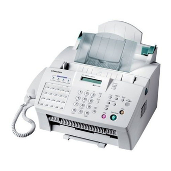
Samsung SF-530 Service Manual
Hide thumbs
Also See for SF-530:
- User manual (168 pages) ,
- Product manual (12 pages) ,
- User manual (58 pages)
Table of Contents
Advertisement
Quick Links
Download this manual
See also:
User Manual
Advertisement
Table of Contents
Troubleshooting

Subscribe to Our Youtube Channel
Related Manuals for Samsung SF-530


Summary of Contents for Samsung SF-530
- Page 1 SAMSUNG FACSIMILE SF-530/531P SERVICE Manual FACSIMILE CONTENTS 1. Precautions 2. Specifications 3. Disassembly and Reassembly 4. Troubleshooting 5. Exploded Views and Parts List 6. Block Diagram 7. Connection Diagram...
- Page 2 ELECTRONICS This service manual is also provided on the web, © Samsung Electronics Co.,Ltd. September 2001 the ITSELF system Samsung Electronics Co., Ltd. Printed in Korea. http://itself.sec.samsung.co.kr VERSION NO. : 1.00 CODE : JC-0059A...
- Page 3 Copyright Act. Specifications are subject to change without prior notice. Samsung Electronics Digital Printing CS Group Copyright (c) 2001. 9.
- Page 4 5. Do not force to open or fasten plastic material compo- away from the part to which nents. it is latched. 6. Be careful that small parts such as screws should not get in the printer. Samsung Electronics...
- Page 5 ESD. 3. Use only a grounded tip soldering iron to solder or desol- der ESDs. Samsung Electronics...
- Page 6 The following tools are recommended for safe and smooth troubleshooting described in this service manual. DCU(Diagnostic Control Unit) Driver Standard: Test equipment to diagnose the Laser Standard: "-" type, "+" type (M3 long, M3 short, printer supplied by Samsung Electronics. M2 long, M2 short). Pinset Standard: For general home use, small type. Cotton Swab...
- Page 7 2.Specifications ITEMS REMARKS SF-530 SF-531P General Size(W*D*H) 370 X 356 X 195 mm Weight 6.9 Kg (With accessories) Power Rating AC 110V ~ 120V ± 15%, 50/60Hz ± 3Hz AC 220V ~ 240V ± 15%, 50/60Hz ± 3Hz Operating Environment Temperature : 10 ~ 32˚C...
- Page 8 Specifications ITEMS REMARKS SF-530 SF-531P Telephone Handset 1-Touch Dial 20 EA 20 EA Speed Dial 80 EA 80 EA Group Dial 20 EA 20 EA Caller ID (Germany, France, Canada, Australia, New Zealand, US) TAD I/F Tone/Pulse Tone : US, UK, Korea...
- Page 9 Win 3.x Win 95 Win 98 Win NT 4.0 Win 2000 Provide After Launch Win 2000 Driver Printer Samsung PrinThru TWAIN Samsung ScanThru (TWAIN) PC-FAX Samsung FaxThru Media CD-ROM Diskette Y2K Compliant Including Software Print/Scan/Copy/Driver, PC-Fax/ E-mail/ OCR Software Special...
- Page 10 2. Be sure to remove the toner cartridge before you disassemble parts. 3. Unplug the power cord. 4. Use a flat and clean surface. 5. Replace only with authorized components. 6. Do not force plastic-material components. 7. Make sure all components are in their proper position. Samsung Electronics...
- Page 11 Then lift, the Roller out. White Roller Note : Check the Roller for any dirt. If dirty, wipe it off with soft cloth dampened with water. If the Roller is heavily worn, replace it with a new one. Control Panel Samsung Electronics...
- Page 12 2. Remove two stoppers holding the front cover unit and unplug one connector and one wire. 6. Lift the OPE cover. 3. Pull the bottom left end of the cover downward to unlatch the front cover unit and remove the cover from the main frame. Samsung Electronics...
- Page 13 Disassembly and Reassembly 7. Remove the stopper holding the OPE cover. 8. Unlatch the bottom ends, then remove the OPE cover. Samsung Electronics...
- Page 14 Alcohol). After wiping it, be sure to dry it. Check the rub- Safely Precautions : ber wear. If the wear reaches 1/2 its original thickness, Do not force to open or fasten plastic material replace it with a new one. components. Pinset or Screw Driver Samsung Electronics...
- Page 15 1. Unlatch the lever sensor Doc from the scan upper frame and take it out. 3-8 Lever Sensor Scan 1. Push the both sides of Lever sensor Scan inward, then unlatch and take out the sensor Scan from the scan upper frame. Samsung Electronics...
- Page 16 – OPE cover (see page 3-3) – Bracket scan board (see page 3-3) 5. Remove two screws and remove the motor. 2. Unplug one connector from the scan board. 3. Remove three screws, then remove the motor Ass’y from the main frame. Samsung Electronics...
- Page 17 2. Remove two screws securing the guide paper and remove the guide paper. Guide Paper 3-12 CIS 1. Remove one screw and push CIS as shown below 2. Separate the Dummy CIS from CIS. and lift it. tape Samsung Electronics...
- Page 18 Then spread the bottom of the top cover and lift the cover to remove. – OPE cover (see page 3-3) – Rear cover (see above) Paper guides 2. Remove two screws securing the top cover from the back side of the machine. Samsung Electronics...
- Page 19 2. Take out the tray from the main frame. 3-16 LSU 1. Before you remove the LSU, you should remove: 3. Unplug two connectors from the LSU and remove the – All covers (see page 3-3, 3-9) LSU. 2. Remove three screws securing the LSU. 3-10 Samsung Electronics...
- Page 20 1. Before you remove the Engine board, you should 2. Unplug five connectors and remove one screw from remove: the engine board, then remove the board. – All covers (see page 3-3, 3-9) – LSU (see page 3-10) Samsung Electronics 3-11...
- Page 21 Note : When you reassemble the pick-up Roller, make sure that the right end of the pick-up Roller fits into the pick-up gear shaft. 3. Remove four screws securing the plate upper and remove the plate upper as below. Pick-up gear shaft 3-12 Samsung Electronics...
- Page 22 1. Before you remove the cap-pad, you should remove: 2. Take out the cap-pad from the main frame. – All covers (see page 3-3, 3-5) – LSU (see page 3-10) – Plate upper (see page 3-12) – Knock-up Ass’y (see above) Samsung Electronics 3-13...
- Page 23 – All covers (see page 3-3, 3-9) Ass’y to allow the screws to be fastened properly. 2. Remove four screws securing the motor Ass’y and unplug one connector from the engine board, then remove the motor Ass’y. Boss 3-14 Samsung Electronics...
- Page 24 1. Before you remove the gear pick-up Ass’y, you 2. Release two snap-fits and remove the gear pick-up should remove: Ass’y from the main frame. – All covers (see page 3-3, 3-9) Note: When reassembling, make sure that the direction of the gear is correct. Samsung Electronics 3-15...
- Page 25 1. Before you remove the HVPS board, you should remove: – All covers (see page 3-3, 3-9) 2. Remove three screws and one connector from the HVPS board, then remove the board. Note : when reassembling, make sure that the terminal is five. 3-16 Samsung Electronics...
- Page 26 3. Remove two screws and unlatch the fuser Ass’y using a proper tool. – All covers (see page 3-3, 3-9) 2. Remove two wires after remove two screws from the main frame and one connector from the inter connec- tor. Samsung Electronics 3-17...
- Page 27 3. Remove the halogen lamp from the heat Roller. remove: – All covers (see page 3-3, 3-9) – Fuser Ass’y (see page 3-17) 2. On the fuser Ass’y, remove the two screws, then remove the heat Roller. 3-18 Samsung Electronics...
- Page 28 2. Lift and remove the pressure Roller from the main frame. 3-33 Actuator-Exit 1. Before you remove the actuator-exit, you should remove: – All covers (see page 3-3, 3-9) – Fuser Ass’y (see page 3-17) 2. Lift and remove the actuator-exit from the main frame. Samsung Electronics 3-19...
- Page 29 1. Before you remove the SMPS board, you should remove: – Rear cover (see page 3-9) – Shield Engine Ass’y (see page 3-19) 2. Remove four screws and three connectors, then remove the SMPS board from the main frame. 3-20 Samsung Electronics...
- Page 30 1. Before you remove the LIU board, you should remove: – Rear cover (see page 3-9) – Shield Engine Ass’y (see page 3-19) 2. Remove three screws and three connectors from the LIU board, then remove the board from the main frame. Samsung Electronics 3-21...
- Page 31 1. Before you remove the sensor board, you should remove: – Rear cover (see page 3-9) – Shield Engine Ass’y (see page 3-19) 2. Release four snap-fits securing the sensor board and unplug one connector from the main board, then remove the sensor board. 3-22 Samsung Electronics...
- Page 32 – Rear cover (see page 3-9) Feed Sensor – Shield Engine Ass’y (see page 3-19) 2. Remove one connector from the main board and two screws securing the holder feed Ass’y, then remove the holder feeder Ass’y. Empty Sensor Samsung Electronics 3-23...
- Page 33 – All covers (see page 3-0) – Motor Ass’y (see page 3-15) 2. Release two snap-fits and remove the gear-feed, clutch-feed, and the spring-clutch. Spring-clutch Gear-feed 4. Separate the Roller Feeder from the Holder Feeder Ass’y. Clutch-feed Roller Feed Holder Feed 3-24 Samsung Electronics...
-
Page 34: Troubleshooting
The technical options you have set in TECH mode are not changed unless you clear the machine’s memory in TECH mode. To communicate via direct connection with another fax machine, press OHD/V.REQ followed by Start/Enter. • Caution : When you finish operating in Tech Mode, you must turn the power Off/On. Samsung Electronics... -
Page 35: Tech Mode
REMOTE TEST OFF/ON NOTIFY TONER LOW OFF/ON ROM TEST ROM OK! (VERSION) CIS TEST DRAM TEST DRAM OK SWITCH TEST DTMF TEST TONER COUNT PRINTING INFO OFF/ON PROGRAM DOWNLODE SCAN COUNT CLEAR COUNT CLEARING .. : Only Tech Mode Samsung Electronics... -
Page 36: Tech Mode Options
• You can select the rate between 5% and 10%. IGNORE TONER EMP • You can set this function ON if desiring to drive the engine continuously even though the life of toner is run out and it becomes Toner Empty status. Samsung Electronics... -
Page 37: Maintenance Options
You may be instructed by a service repre- sentative to enable this feature. • Caution : After replacing Main board to new one, you should update the information to the new board. Samsung Electronics... - Page 38 PC that is connected to the machine with a parallel cable (IEEE 1284). SCAN COUNT CLEAR • If performing this feature, the value of scanning original until now is initialized (0). (Total scan count value on the system data list becomes 0.) Samsung Electronics...
-
Page 39: Printout Report
This function is for a manufacturing press . You can test all function(1~15) • When you push the “Start” button, the Main Motor runs. • If you push the “Start” button again , the current test stops, and the next test starts. Samsung Electronics... -
Page 40: Maintenance List
S DIS 00000000 01110111 00010111 00100010 R TSI 2020202020202020202020202O20202020202020 R DCS 00000000 01100001 00010101 00000000 S FTT R TSI 2020202020202020202020202O20202020202020 R DCS 00000000 01100001 00010101 00000000 S CFR R MPS S MCF S DCN < SAMPLE OF A PROTOCOL DUMP LIST > Samsung Electronics... -
Page 41: Diagnostics
NO ANSWER the redial attempts. is operational. The one-touch or speed dial location you tried Dial the number manually with the key- NO. NOT ASSIGNED to use has no number assigned to it. pad, or assign a number. Samsung Electronics... - Page 42 The toner is almost empty. Take out the toner cartridge and gently shake it. Using this way, you can tem- porarily re-establish the print quality. WARMING UP The printer is warming up and is off-line. Wait until the printer is on-line. Samsung Electronics...
-
Page 43: Print Quality
4. In Tech mode, print ‘SYSTEM DATA LIST’ and make sure tridge can print. (The yield of a new toner cartridge is that the toner information is updated. approximately 2,500 pages and that of the cartridge supplied with the machine is approximately 1.000 pages.) 4-10 Samsung Electronics... -
Page 44: Troubleshooting Flow Chart
OK after removing the obstacles? OK after Remove part on the paper replacing the LSU? path causing the trouble Any obstacles ON mirror lens of LSU and Replace the LSU laser path? Remove the obstacles. Samsung Electronics 4-11... - Page 45 LSU transit to High/Low the defective component when printing? or board The mirror in LSU might be misplaced so the light path to the OPC deviates ->Repair or replace LSU or remove any deffective matters in the machine 4-12 Samsung Electronics...
- Page 46 This could occurrs when he power of LSU is low or the toner’s guarranty the density is low due to the obstacles on the window life -> Replace LSU or clean the window Replace the toner cartridge Samsung Electronics 4-13...
- Page 47 HVPS works OK? Any obstacles on the gab between high voltage Remove the obstacles terminal and developer? Clean transfer roller Transfer roller and gear holder works OK? OK after replacing Replace the LSU LSU? Replace the developer 4-14 Samsung Electronics...
- Page 48 -> Repair or replace printing? the boards Replace LSU Is transfer voltage supplied Repair or replace HVPS (-1.55 KV)? Is the Hsync/ signal received Replace LSU in LSU? Transfer part’s contact is bad -> Repair or replace toner cartridge Samsung Electronics 4-15...
- Page 49 Toner material might be stuck to blade in the developer inside and it prevents toner supply -> Replace the toner cartridge Check both if the toner cartridge’s counter is over its guaranty and amount of the toner material -> Replace the toner cartridge 4-16 Samsung Electronics...
- Page 50 Toner over supply due to the Works adjustment fault of metering correctly after blade in developer replaced LSU? -> Replace developer The power of LSU is set high or internal problem -> Replace LSU or adjust voluem Samsung Electronics 4-17...
- Page 51 (10-32 degree Centigrade) /terminal after check Check Terminals or contacts and ’Guide-Deve Spring’ are misplaced Work OK? -> Repair or replace transfer roller etc. Internal blade or suppying part of the developer is defective -> Replace the toner cartridge 4-18 Samsung Electronics...
- Page 52 HVPS Operating/storage There may be a problem in toner temperature is too low or layer control in toner cartridge not recommended -> Replace the developer paper used? Use the machine with recommended paper and at condition Samsung Electronics 4-19...
- Page 53 P/R or H/R in fuser the paper -> Replace the -> Clean it or replace developer The problem occured Does the same since the obstacles problesm stuck to charge roller persist? -> Replace toner cartridge 4-20 Samsung Electronics...
- Page 54 (37.7mm) -> Repair/replace HVPS, developer The OPC is damaged due to Heat roller is ruined the irregular transfer voltage -> Replace the roller of HVPS -> Repair/replace HVPS -> If the same problem persists, replace the developer Samsung Electronics 4-21...
- Page 55 Troubleshooting Toner Contaminations on Back of Paper Transfer roller Clean the transfer roller is clear ? Paper path is Clean the paper path clear ? Clean the pressure roller 4-22 Samsung Electronics...
- Page 56 Clean the TR holder, the TR gear, works properly? OPC roller gear and the transfer roller - Clean the contact point of transfer roller - Check the output of high voltage terminal and adjust or replace if required Samsung Electronics 4-23...
- Page 57 - Check the output of high voltage terminal and adjust or replace if required. Is it regular interval of 75.4mm, 31.6mm Replace the toner cartidge or 37.7mm? Replace the fuser (50.2mm, 45.2mm or exit roller 4-24 Samsung Electronics...
- Page 58 (Check the counter replace terminals, HVPS and replace it) Irregualrity of toner Bad images suppy from developer aroung the no image -> Repalce developer area? Light distortion due to the mirror ruined or LSU’s diffused reflection -> Replace LSU Samsung Electronics 4-25...
- Page 59 Obstacles stuck on OPC’s D/R in developing unit has surface the defect -> Clean the OPC and -> Replace the developer machine or replace developer When putting in/out the developer, scratch is made -> Replace the developer 4-26 Samsung Electronics...
- Page 60 Use the recommended film than 10 films into temporarily stops the MPF? and revolves? Other parts are touching the When multi-page OHP printng, fan and prevents it from less than 10 films are revolution guranteed. -> Check and repair Samsung Electronics 4-27...
- Page 61 1.2~ 3.0mm? Replace the contol The paper used is too component on engine thick or contains too board much cotton in it -> Re-test with the Check any contact recommended paper problem in thermistor and repair 4-28 Samsung Electronics...
- Page 62 -> Replace the boards Detect failure due to the Repair/replace the Remove the shortage board board which detects top or replace the board cover open or switch error -> Replace the board or switch Samsung Electronics 4-29...
- Page 63 -> Replace the component or replace the SMPS The voltage of pin #208 of U5 Thermistor, connecting point or engine (CPU) on the Main board board defect -> Repair/replace the is about 2.3V when component/board printing? 4-30 Samsung Electronics...
- Page 64 Switch them Does the Pull out the Paper end curled? extender pulled out? extender <Recommendation> Use the recommended Use the MPF for the thick and quality paper paper such as envelope and cardstock Samsung Electronics 4-31...
- Page 65 Adjust the paper guides to fit the or sensitive paper to is grounded Check paper width static electricity? the shutter prevents feeding The force of springs pressing the developer is weak -> Check guide-DEVE Use the recommended paper 4-32 Samsung Electronics...
- Page 66 B’D) Replace connector Check MAIN B’D CN9-3, Replace MAIN B’D P_MOTOR Signal Check MAIN B’D CN9-4, Replace LSU LREDADY Signal Check MAIN B’D CN9-9, Replace MAIN B’D LDON Signal Check MAIN B’D CN9-6, Replace LSU HSYNC Signal Samsung Electronics 4-33...
-
Page 67: Exploded Views And Parts List
5. Exploded Views and Parts List 5-1 Main Assembly 5-2 Shield Engine Unit Assembly 5-3 Engine Assembly 5-4 Frame Lower Assembly 5-5 Fuser Assembly 5-6 Plate-Upper Unit Assembly 5-7 OPE Unit 5-8 Scan Upper Assembly 5-9 Front Assembly 5-10 RX Drive Unit Assembly Samsung Electronics... - Page 68 Exploded Views and Parts List 5-1 Main Assembly 18-2 16-2 16-1 18-1 14-1 14-2 19-2 19-1 10 &12 17-2 17-1 Samsung Electronics...
- Page 69 Exploded Views and Parts List Main Assembly Parts List O : Service available X : Service not available Description SEC.Code Q’ty Remark SF-530 / 531P SMPS-V1 JC44-00032A 110V SMPS-V2(4CH) JC44-00023A 220V UNIT-LSU JC59-00006A IPR-PLATE_CHANNEL JC70-00058A MEC-PLATE UPPER JC75-00057A MEC-TRAY JC75-00062A...
- Page 70 Exploded Views and Parts List 5-2 Shield Engine Unit Assembly LIU B’d Samsung Electronics...
- Page 71 Exploded Views and Parts List Shield Engine Unit Assembly Parts List O : Service available X : Service not available Description SEC.Code Q’ty Remark ELA HOU-SHIELD ENGINE SF-530 ELA HOU-SHIELD ENGINE SF-531P CABLE-FLAT 3809-001161 CBF HARNESS-LSU JC39-00043A CBF HARNESS-MAIN-HVPS JC39-00193A...
-
Page 72: Engine Assembly
Exploded Views and Parts List 5-3 Engine Assembly 13-1 13-2 21-1 21-2 S-10 21-3 17-2 17-3 17-4 17-1 22-3 22-1 22-2 Frame Lawer Ass’y Bushing-Shaft Samsung Electronics... - Page 73 17-4 RPR-PAD FRICTION MEC-TERMINAL JC75-00049A MEC-SIDE PAD(L) JC75-00050B MEC-SIDE PAD(R) JC75-00051B MEC-KNOCKUP ASS’Y JC75-00053A 21-1 IPR-BAR_KNOCKUP 21-2 PMO-PLATE-KNOCKUP 21-3 PMO-CAM-KNOCKUP MEC-GEAR PICK UP JC75-00056A 22-1 SPRING-PICK UP GEAR 22-2 PMO-GEAR_PICKUP,1 22-3 PMO-GEAR_PICKUP,2 SCREW-TAPTITE 6003-000196 SCREW-TAPTITE 6003-000266 SCREW-TAPTITE 6003-000119 Samsung Electronics...
-
Page 74: Frame Lower Assembly
Exploded Views and Parts List 5-4 Frame Lower Assembly 29-4 29-1 Transfer Roller 29-3 29-2 30-3 30-1 30-2 34-1 34-2 27-1 27-2 28-3 28-4 28-3 28-5 28-1 28-2 Samsung Electronics... - Page 75 ELA HOU-PTL ASS’Y JC96-02312A ELA HOU-FUSER 110V JC81-00439A 110V ELA HOU-FUSER 220V(531P) JC81-00440A 220V PMO-BUSHING SHAFT JG72-40849A GEAR-FU_IN 47 JC66-00306A PMO-HUB GEAR JC72-00676A GEAR-FU_OUT 47 PMO-GEAR_83/35 JC72-00154A IPR-BRACKET FUSER DRV FAN-DC 3103-001085 SCREW-TAPTITE 6003-000152 SCREW-TAPTITE 6003-000196 SCREW-TAPTITE 6003-000119 Samsung Electronics...
-
Page 76: Fuser Assembly
Exploded Views and Parts List 5-5 Fuser Assembly 14-2 14-1 5-10 Samsung Electronics... - Page 77 NPR-ROLLER HEAT JC71-00012B IPR-ELECTRODE_PLATE IPR-GROUND_FU IPR-PIN ROLLER EXIT IPR-ELECTRODE WIRE1 IPR-ELECTRODE WIRE,S MEA ETC-SHAFT EXIT 14-1 PMO-SHAFT_EXIT(Z15) JC72-00150A 14-2 RMO-RUBBER_EXIT PMO-ROLLER_IDLE EXIT JC72-00567A SPRING-EXIT JC61-00017A PMO-GEAR_EXIT_DRV16 PMO-GEAR_EXIT_IDLE GEAR-FUSER 1210 JC66-00037B LABEL(R)-CAU_HOT_FU SPRING-CLAW PMO-GUIDE CLAW SCREW-TAPTITE 6003-000119 SCREW-TAPTITE 6003-000196 Samsung Electronics 5-11...
-
Page 78: Plate-Upper Unit Assembly
Exploded Views and Parts List 5-6 Plate-Upper Unit Assembly 5-12 Samsung Electronics... - Page 79 Remark MEC-PLATE UPPER JC75-00057A IPR-UPPER-PLATE IPR-PLATE SPRING DEV JC70-10223A ELA UNIT-FUSE DEVE MEA ETC-ROLLER PICK UP PMO-HOUSING_PICKUP JC72-00109A RMO-ROLLER_PICKUP PMO-IDLE_PICKUP MEA ETC-IDLE FEED PMO-HOLDER_PICKUP SPRING-FEED PMO-HOLDER_IDLE,FEED CABLE CLAMP 6502-000130 ICT-ROLLER IDEL FEED SCREW-TAPTITE SCREW-TAPTITE 6003-000266 SCREW-TAPTITE 6003-000266 Samsung Electronics 5-13...
-
Page 80: Ope Unit
Exploded Views and Parts List 5-7 OPE Unit OPE Unit Parts List O : Service available X : Service not available Description SEC.Code Q’ty Remark ELA HOU-OPE ASS’Y JC81-00442A SF-530 ELA HOU-OPE ASS’Y JC81-00468A SF-531P SCREW-TAPTITE 6003-000119 MPR-COVER ADRESS JG74-10543A PMO-KEY COPY JB72-00102A... -
Page 81: Scan Upper Assembly
MPR-TAPE ADF CBF HARNESS-SCAN GND JC39-00101A SPRING-SENSOR SPRING-COIL ADF JC61-00040A PMO-SCAN UPPER JC72-00671A PMO-LEVER SENSOR DOC JC72-00823A PMO-LEVER SENSOR JC72-41322A ICT-SHAFT PINCH JF70-40521B PMO-HOLDER RUBBER JG72-40044A PMO-ROLL PINCH JG72-40663A PMO-SUPPORT ADF JG72-41083A RPR-RUBBER ADF JC73-00032A MEC-BRUSH ANTISTATIC JG75-10004A Samsung Electronics 5-15... -
Page 82: Front Assembly
Exploded Views and Parts List 5-9 Front Assembly Bushing White 5-16 Samsung Electronics... - Page 83 PMO-OPEN LOCKER L PMO-OPEN LOCKER R PMO-BRKT SCAN B’D JC72-00222A PMO-OPEN BUTTON JC72-00273A PMO-COVER MOTOR JC72-00670A PMO-COVER FRONT JC72-00673A PMO-DUMMY CIS L SF-530 JC72-00880A SF-530 PMO-DUMMY CIS L JC72-00495A SF-531P PMO-DUMMY CIS R SF-530 JC72-00881A SF-530 PMO-DUMMY CIS R JC72-00496A...
-
Page 84: Rx Drive Unit Assembly
5-10 RX Drive Unit Assembly RX Drive Assembly Parts List O : Service available X : Service not available Description SEC.Code Q’ty Remark ELA HOU-RX DRIVE JC96-01755A MOTOR-STEP JC31-00005A PMO-GEAR_71/28 PMO-GEAR_73/22 PMO-GEAR_132/19 IPR-BRKT_MOTOR IPR-BRKT_GEAR JC70-00129A CBF-HARNESS_MOTOR JC39-00110A SCREW-MACHINE 6001-000131 YELLOW 5-18 Samsung Electronics... -
Page 85: Block Diagram
6. Block Diagram Samsung Electronics... - Page 86 Repair Manual Repair Manual SAMSUNG FACSIMILE SF-530/531P CONTENTS 1. Block Diagram 2. Connection Diagram 3. Circuit Description 4. Schematic Diagrams...
- Page 87 Electronics...
- Page 88 This manual is made and described centering around circuit diagram and circuit description needed in the repair center in the form of appendix. Samsung Electronics Digital Printing CS Group Copyright (c) 2001. 10...
- Page 89 BLOCK DIAGRAM 1. Block Diagram Repair Manual Samsung Electronics...
-
Page 90: Connection Diagram
4 L I NR_ 5 HOOK B’d 6 HOOK2 _NC 5 L I NR_ 6 LIU B’d 7 HOOK2 _NO 6 EXT_ 3 1 0 HOOK1 7 EXT_ 4 1 1 HOOK1_ NO 8 EXT_ 5 1 2 HOOK1_ NC Repair Manual Samsung Electronics... - Page 91 Interface Video Data Position & Controller Fire Control UART/ Paper Motor Serial I/O Control Real Time Control Clock Watch Dog PWM & Timer Gen. Timer System Manager System Bus Controller Bus Arbitration Bus Interface ROM/SRAM/DRAM Controller Repair Manual Samsung Electronics...
- Page 92 • CLOCK 1) System Clock Device Oscillator Frequency 9.500132 MHz KS32C65100 RISC PROCESSOR: drives PLL internally and uses 37.17 MHz. 2) Video Clock Device Oscillator Frequency 28.7448 MHz 3) USB Clock Device Oscillator Frequency 48 MHz±% Repair Manual Samsung Electronics...
- Page 93 This 8-bit, tri-state bus is used to PPD[7:0] 142~149 I/O2 exchange data between the KS32C65100 and an external host(peripheral). SAVRT Top reference voltage for IP ADC SAIN Analog input for IP ADC SAVRB Bottom reference voltage for IP ADC Repair Manual Samsung Electronics...
- Page 94 Not write enable. Whenever a memory access occurs, the nWE output controls the write enable port of the specific memory device. nPHGA[13:1]/ 16~24, Gate control line for print head. 26~29 GOPB[12:0] PHOE[16:1]/ 31~38, I/O1 Drain control line for print head. 40~47 GIOP[26:11] Repair Manual Samsung Electronics...
- Page 95 Test 0 pin. At normal operation this pin must be connected TEST0 to GND. Test 1 pin. At normal operation this pin must be connected TEST1 to GND. Test 2 pin. At normal operation this pin must be connected TEST2 to GND. Repair Manual Samsung Electronics...
- Page 96 Externally connected to the 3.3V regulator. 5V I/O power. 48, 67, 89, 5VDD 141, 195 Externally connected to the VCC board plane. 11, 25, 39, 58, 76, 101, System ground. 108, 124, Externally connected to the ground board plane. 150, 172, Repair Manual Samsung Electronics...
- Page 97 DRAMWE*SIGNAL is activated when writing data and DRAMOE*SIGNAL, when reading. 3-1-5 USB (Universal Serial Bus) SAMSUNG’S UNICON is used as the interface IC and 48MHz clock is used. When the data is received through the USB port, USBIRQ SIGNAL is activated to send interrupt to CPU, then it directly sends the data to DRAM by USB_CS SIGNAL through D(0;7).
- Page 98 • Two 16-byte FIFO data buffers for burst data transfer with extension up to 255 bytes • NRZI encoding/decoding • Diagnostic capability • +3.3V operation with +5V tolerant inputs • +5V analog signal interface • Typical power consumption:- Sleep mode: 20 mW - Normal mode: 250 mWa • 100-pin PQFP package Repair Manual Samsung Electronics...
- Page 99 Differential Phase Shift Keying 2. Adaptive; established during handshake: Carrier Frequency (Hz) Symbol Rate (Baud) V.34 Low Carrier V.34 High Carrier 2400 1600 1800 2800 1680 1867 3000 1800 2000 3200 1829 1920 3429 1959 1959 Repair Manual Samsung Electronics...
- Page 100 Eye Pattern D[7:0] EYECLK Generator Host RS[4:0] Processor /RESET Speaker TXRQ* SPKR Amplifier RXRQ** +3.3V Power Supply AGND DGND * Selectable; TXRQ output replaces /RI output. ** Selectable; RXRQ output replaces /DSR output. 1176DG F2-1 Repair Manual 3-10 Samsung Electronics...
- Page 101 OA, OB = Digital output. I(DA) = Analog input. O(DD), O(DF) = Analog output. NC = No external connection required. RESERVED = No external connection allowed. Interface Legend: HOST = Modem Control Unit (Host) DTE = Data Terminal Equipment Repair Manual 3-11 Samsung Electronics...
- Page 102 VC pin. The SPKR output can drive an impedance as low as 300 ohms. In a typical application, the SPKR output is an input to an external LM386 audio power amplifier. Repair Manual 3-12 Samsung Electronics...
- Page 103 Transmit Data. The modem obtains serial data to be transmitted from the local DTE on the Transmit Data (TXD) input in serial data mode (TPDM bit = 0), or from the interface memory Transmit Data Register (TBUFFER) in parallel data mode (TPDM bit = 1). Repair Manual 3-13 Samsung Electronics...
- Page 104 Data Hold Time TDHR — Control Hold Time — Notes: /CS and /RD must not both be continuously active. A read or write operation following a read operation must be delayed by at least 2 XCLK cycle. Repair Manual 3-14 Samsung Electronics...
- Page 105 XTALO/NC XTALO PLL_VDD PLL Supply Voltage. PLL_GND DGND PLL Supply Voltage return. VCORE 3.3V Supply Voltage. Connect to VDD1. RESERVED Reserved pins are used for future development and should not be connected to any circuitry. Repair Manual 3-15 Samsung Electronics...
- Page 106 0V DC ; reference point Clock CIS main clock LEDB LED Ground (blue) LED POWER SUPPLY BLUE LEDG LED Ground (green) LED POWER SUPPLY GREEN LEDR LED Ground (red) LED POWER SUPPLY RED VLED Supply voltage LED POWER SUPPLY Repair Manual 3-16 Samsung Electronics...
- Page 107 LED Current ILEDr REF. ILEDg REF. ILEDb REF. Clock Frequency. Clock Pulse “L” Duty tw/to Setup Time tw/2 Hold Time tw/2 SIG Delay Time tpd 1 tpd 2 Sampling Reriod CIS Driver Clock Timing tpd2 tpd1 Repair Manual 3-17 Samsung Electronics...
- Page 108 ROD LENS ARRAY 20 21 SENSOR SHIFT REGISER & ANALOG SWITCH OP AMP 2.5ms 1.2ms 1.2ms LED_R 1.2ms LED_G 1.2ms LED_B SIG O/P B O/P R O/P G O/P B O/P R O/P G O/P 7.5ms/line Repair Manual 3-18 Samsung Electronics...
- Page 109 PC data printing, high speed uploading of scanned data to PC, upload/download of the fax data to send or receive and monitoring the system control signal and overall system from PC are all processed through this part. Repair Manual 3-19 Samsung Electronics...
- Page 110 4. Host sets nSTROBE high. This is the edge that should be used to clock the data into the Peripheral 5. Peripheral sets BUSY low to indicate that it is ready for the next byte 6. The cycle repeats, but this time it is a command cycle because nAUTOFD is low Repair Manual 3-20 Samsung Electronics...
- Page 111 6. Peripheral sets nACK high. This is the edge that should be used to clock the data into the host 7. Host sets nAUTOFD low to indicate that it is ready for the next byte 8. The cycle repeats, but this time it is a command cycle because BUSY is low Repair Manual 3-21 Samsung Electronics...
- Page 112 - Three Receive Endpoints (2*32 and 1*64 bytes) • 8-bit parallel interface with two selectable modes : - non-multiplexed - multiplexed (Inter compatible) • DMA support for parallel interface • MICROWIRE/PLUS Interface • 28-pin SO package Repair Manual 3-22 Samsung Electronics...
- Page 113 CIRCUIT DESCRIPTION NON-MULTIPLEXED MODE INTERFACE BLOCK DIAGRAM DATA_IN 0x00 DATA_IN DATA_OUT DATA_OUT D[7:0] ADDRESS ADDR 0x3F REGISTERFILE NON-MULTIPLEXED MODE BASIC TIMING DIAGRAM D[7:0] input vvrte Address Read Data Burst Read Data Repair Manual 3-23 Samsung Electronics...
- Page 114 UART line and then the main drives neces- • Scan position sensor output is received at U2 pin7 Scan RESONATOR Position 7.37 MHz Sensor Document 16x 1Line Detect MICOM Sensor HT48C5A Key Matrix UART Connector Reset LEDs <OPE BLOCK DIAGRAM> Repair Manual 3-24 Samsung Electronics...
- Page 115 The telephone circuit is comprised of ring detect circuit, dialer circuit, speech circuit, external hook detect circuit and recall circuit. (1) Ring Detect Circuit (2) Dialling Circuit (including MF Dialling Signal Transmitting Circuit) (3) Speech Circuit (4) External Hook Detect Circuit (5) Recall Circuit Repair Manual 3-25 Samsung Electronics...
- Page 116 ARS2 to FAX to TEL ARS1 RING ARS3 <TEL_LINE INTERFACE CIRCUIT> Repair Manual 3-26 Samsung Electronics...
- Page 117 In this case, the time break recall was enabled by switching the power transistor of the telephone circuit using the secondary CPU control. Repair Manual 3-27 Samsung Electronics...
- Page 118 It is comprised of heat lamp, heat roller, pressure roller, thermistor and thermostat. It fixes the toner powder transferred to the paper on the paper using pressure and high heat in order to finish the final printing job. Repair Manual 3-28 Samsung Electronics...
- Page 119 -50V(forms black dot) and the part retaining -800V will be white in order to make the basic condition to form the video data. 2.Charging 3.Exposure 4.Development 7.Fixing 8.Exit 1.Feeding EXIT FEED SENSOR SENSOR 6.Transfer 5.Pre-Transfer < Engine Operating Description > Repair Manual 3-29 Samsung Electronics...
- Page 120 Toner on the OPC drum is transferred to paper by transfer unit. In other words, the toner on the OPC drum surface is induct- ed by the transfer roller electrified to approximately +1.3KV(600~2800V variable) to the paper. At this point, the voltage (600~2800V variable) is determined by temperature and humidity. The above process is called “transfer”. Repair Manual 3-30 Samsung Electronics...
- Page 121 After the digital picture process is finished, the printed paper will come out of the set through the exit sensor. The signal detected will be transferred to the engine and provide the position information. If the actuator and the sensor do not work normally, the system will display “Paper Jam 2 Error”. Repair Manual 3-31 Samsung Electronics...
- Page 122 DEV-EA SWITCHING CONTROL UNIT SUPPLY-EA TRANSFER OUTPUT UNIT BLOCK DIAGRAM THVPWM REGULATION SWITCHING CONTROL UNIT CIRCUIT TRANS CONTROL UNIT FE E DBACK THVEA SWITCHING REGULATION TRANS CONTROL UNIT CIRCUIT THVREAD FEED BACK ENVIRONMENT RECOGNITION CIRCUIT Repair Manual 3-32 Samsung Electronics...
- Page 123 MHV OUTPUT 24VS C404 3K/471 C406 D402 3K/471 Q402 R405 220K U2 7407 R416 Q401 A708 D526 MHV-PWM 24VS R411 2.2K R417 R408 R409 R403 130K R404 R402 KA324 C403 C408 R412 2K R406 2.2K Repair Manual 3-33 Samsung Electronics...
- Page 124 DEV-EA R115 3.3K ZD403 51V Q106 C3198 R106 Q105 A1413 SUPPLY 24VS OUTPUT R111 R107 ZD404 150V R110 C106 2.2K 1K/101 R109 10K ZD405 150V SUPPLY-EA R108 33K ZD406 100V Q104 R112 ZD407 100V C3198 Repair Manual 3-34 Samsung Electronics...
- Page 125 R310 Q303 2.2K D526 Q302 A708Y R308 VR302 TEV-READ R302 R303 R304 R306 C305 100KF R311 R314 389KF 26.1KF KA324 333Z 1.7K 100KF C302 C303 D302 R305 1N4148 R301 10KF 470K C304 500V103Z VR301 C301 Repair Manual 3-35 Samsung Electronics...
- Page 126 CPU, the transfer voltage output will differ according to the preset transfer table. The changes in transfer output required by each load is controlled by PWM-DUTY. Repair Manual 3-36 Samsung Electronics...
- Page 127 SCHEMATIC DIAGRAMS 4.Schematic Diagrams 4-1 Main Circuit Diagram (1/6) APOLLO2(MAIN) Repair Manual Samsung Electronics...
- Page 128 SCHEMATIC DIAGRAMS 4-2 Main Circuit Diagram (2/6) APOLLO2(MAIN) Repair Manual Samsung Electronics...
- Page 129 SCHEMATIC DIAGRAMS 4-3 Main Circuit Diagram (3/6) APOLLO2(MAIN) Repair Manual Samsung Electronics...
- Page 130 SCHEMATIC DIAGRAMS 4-4 Main Circuit Diagram (4/6) APOLLO2(MAIN) Repair Manual Samsung Electronics...
- Page 131 SCHEMATIC DIAGRAMS 4-5 Main Circuit Diagram (5/6) APOLLO2(MAIN) Repair Manual Samsung Electronics...
- Page 132 SCHEMATIC DIAGRAMS 4-6 Main Circuit Diagram (6/6) APOLLO2(MAIN) Repair Manual Samsung Electronics...
- Page 133 SCHEMATIC DIAGRAMS 4-7 LIU Circuit Diagram (1/2) APOLLO2(LIU) Repair Manual Samsung Electronics...
- Page 134 SCHEMATIC DIAGRAMS 4-8 LIU Circuit Diagram (2/2) APOLLO2(LIU) Repair Manual Samsung Electronics...
- Page 135 SW45 SW30 SW26 SW31 SW36 SW41 KPI-L05 D_DET D_SCAN ITR-9702/F2 100nF 100nF Engineer: Ho-Jin Park SAMSUNG ELECTRONICS Drawn by: Ho-Jin Park R&D CHK: Size: TITLE: GND5 GND5 GND5 GND5 DOC CTRL CHK: APOLLO2 (OPE) MFG ENGR CHK: Time Changed: QA CHK:...
- Page 136 SCHEMATIC DIAGRAMS 4-10 Scan Circuit Diagram (200DPI) APOLLO2(200DPI) Repair Manual 4-10 Samsung Electronics...
- Page 137 SCHEMATIC DIAGRAMS 4-11 Scan Circuit Diagram (300DPI) APOLLO2(300DPI) Repair Manual 4-11 Samsung Electronics...
- Page 138 A-GND 24VS THV-PWM B1151-Y KA7818 THV-EA THV-READ MHV-PWM 1W 1K BIAS-PWM APOLLO2 (HVPS) DONGYANG INSTRUMENTS TITLE D-GND 35V 47uF DRW. NO 5.6K DESIGNED CHECKED APPROVED C1008-Y REV. REF. NO J.S.YOUN SIZE A4 1 OF 2 Repair Manual 4-12 Samsung Electronics...
- Page 139 KA324 200KF C303 R317 R305 6.2KF C302 R301 D302 470K 1N4148 C304 500V 103 VR301 APOLLO2 (HVPS) DONGYANG INSTRUMENTS TITLE C301 DESIGNED CHECKED APPROVED DRW. NO REV. REF. NO J.S.YOUN SIZE A4 2 OF 2 Repair Manual 4-13 Samsung Electronics...
- Page 140 Roller Feeder ..........3-24 Samsung Electronics...
-
Page 141: Table Of Contents
7. Connection Diagram ......... . .7-1 Samsung Electronics...
Need help?
Do you have a question about the SF-530 and is the answer not in the manual?
Questions and answers