CAME G3750 Installation Manual
Street barrier
Hide thumbs
Also See for G3750:
- Installation manual (28 pages) ,
- Quick start manual (12 pages) ,
- Installation manual (96 pages)
Table of Contents
Advertisement
Quick Links
Advertisement
Table of Contents

Related Manuals for CAME G3750


Summary of Contents for CAME G3750
- Page 1 Street barriers FA01237-EN G3750 INSTALLATION MANUAL EN English...
- Page 2 • T close supervision or once They have been properly insTrucTed To use The his producT should only be used for The purpose for which iT was . caMe s. apparaTus safely and To The poTenTial hazards involved hildren MusT...
- Page 3 The barrier is designed for use in private and public parking facilities, in residential settings and for high-rates of vehicle traffic. Any installation and use other than that specified in this manual is forbidden. Limits to use Model G3750 Maximum clearance width of the passage (m) 3.75 Technical data...
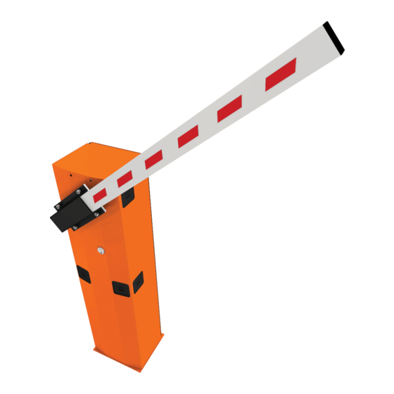
- Page 4 Description of parts Cabinet Gearmotor Transmission-shaft plate Control panel Boom-attachment cover Balancing spring Anti-shearing protective cover 10. Inspection hatch Gearmotor release with customized key Hatch lock with customized key Standard installation Barrier Photocell casing Flashing light Photocells post Semi-oval boom Fixed rest Luminous cord 10.
- Page 5 GENERAL INSTRUCTIONS FOR INSTALLING ⚠ Installation must be carried out by expert qualified personnel and in full compliance with the regulations in force. Important! Using original CAME control and safety devices and accessories ensures easy installation and system maintenance. Preliminary checks ⚠...
- Page 6 INSTALLATION ⚠ The following illustrations are mere examples. Consider that the space available where to fit the barrier and accessories will vary depending on the area where it is installed. It is up to the installer to find the most suitable solution. ⚠...
- Page 7 Place the plate over the iron cage. Fill the foundation frame with concrete. The base must be perfectly level with the bolts which are entirely above surface. Wait at least 24 hrs for the concrete to solidify. Remove the foundation frame. Fill the hole with earth around the concrete block.
- Page 8 Place the cabinet onto the anchoring plate and fasten it using nuts and washers. M12 UNI 5588 nut Washer To change the rotation at a later date, request the documentation from your local retailer or contact Came in your Country (see the last page or visit www.came.com) Entry side...
- Page 9 Fit the shock-resistant frame to the boom's lower side. Fit the boom into the boom-attaching cover and fasten it using the screws. Note: to mount with the G0402 boom, fit and fasten the two spacers (supplied with the boom) in the boom attachment, as shown in the figure.
- Page 10 Cut the groove profiles to length and fit them into the boom's groove. Perform this procedure on both ends. Fit the cap onto the end of the boom. Fit and fasten the anti-shearing protective cover onto the boom attachment-cover.
- Page 11 Balancing the boom Before proceeding, check that the spring you have chosen is suitable for the accessories and the clearance. G03750 Passage clearance (3.75 m max.) 001G04060 Ø 50 mm 001G02040 Ø 40 mm springs 001G06080 Ø 55 mm springs springs BOOM COMPOSITION (m) 1.5 to 1.75...
- Page 12 Release the gearmotor and position the boom vertically. Lock the gearmotor again. RELEASING Screw the spring onto the anchoring pin, hooked onto the transmission arm. Hook the eyelet rod on the spring onto the anchoring bracket.
- Page 13 Manually turn the balancing spring to increase or reduce the traction force so that the boom balances at a 45-degree angle. Fasten the rod nut and lock the gearmotor again. Note: check the proper working state of the spring: - with the boom raised vertically, the spring is not taut; - with the boom lowered horizontally, the spring is taut.
- Page 14 ELECTRICAL CONNECTIONS AND PROGRAMMING ⚠ Warning! Before working on the control panel, cut off the main current supply and, if present, remove any batteries. Power supply to the control panel and control devices: 24 V AC/DC. The features are set using the DIP switches, the adjustments using the trimmer. All connections are quick-fuse protected.
- Page 15 Factory wiring The gearmotor is already connected. To install the barrier on the right, follow the instructions in the PREPARING THE BARRIER paragraph. Opening micro 24 V DC gearmotor switch Orange White Orange Blue Brown Closing micro switch PT F FC FA E +10 -11 1 C1 C5 Warning devices...
- Page 16 Safety devices DIR photocells DELTA-S photocells Configure contact C1 and/or C5 (NC), input for safety devices such as photocells, which comply with EN 12978 regulations. C1 reopening while closing. When the boom is closing, opening the contact causes its movement to invert until fully opened;...
- Page 17 Keep the PROG programming button pressed on the control board. The programming LED will flash . Press a button on the transmitter you wish to memorize. The LED stays lit to confirm that the transmitter is now memorized. . 3 4 5 6 7 8 9 10 PROG key Programming LED...
- Page 18 To correct the horizontal position (=closing), raise the bar, adjust the mechanical closing stop and secure it with the counter nut. counter nut Mechanical closing stop Adjusting speed Min. = minimum Med. = medium Max. = maximum COM = common DIS.
- Page 19 Trimmer adjustments SENS. A.C.T. 3 4 5 6 7 8 9 10 SENS. A.C.T. Trimmer Description of functions Sensitivity SENS It adjusts the obstruction detection sensitivity during gate movement. Minimum sensitivity (-) or maximum sensitivity (+). Automatic Closing Time A.C.T. It regulates the open barrier's waiting time.
- Page 20 FINAL OPERATIONS When you have completed the electrical connections and setting up, fit the control panel cover,replace the inspection hatch . Lock the hatch by using the key . RELEASING THE BOOM ⚠ This procedure must be done with the mains power cut off. ...
- Page 21 PAIRED CONNECTION WITH A SINGLE COMMAND Establish the Master barrier and the Slave barrier. MASTER SLAVE On the MASTER barrier's electronic board, make the necessary electrical connections, activate the radio control, program the functions and settings. MASTER 3 4 5 6 7 8 9 10 On the SLAVE barrier's control board, connect the power supply to L-N, the flashing light on 10-E, set DIP switch 7 to ON and adjust the travel and slow-down speeds just like on the MASTER barrier.
- Page 22 TROUBLESHOOTING PROBLEM REFERENCE CHECK The barrier neither opens nor closes 1-2-3-4-6-8-18 1 - Lock the inspection hatch with the key The boom opens but does not close 4-7-10 2 - Deactivate the MAINTAINED ACTION function The boom closes but does not open 4-7-9 3 - Check the power supply and fuses The barrier does not automatically close...
- Page 23 ________________________________________________________________________________________________ DISMANTLING AND DISPOSAL ☞ CAME S.p.A. complies with a certified Environmental Management System at its premises, compliant with the UNI EN ISO 14001 standard to ensure the environment is safeguarded. Please continue safeguarding the environment. At CAME we consider it one of the fundamentals of our operating and market strategies. Simply...
- Page 24 CAME S.p.A. Via Martiri Della Libertà, 15 31030 Dosson di Casier - Treviso - Italy tel. (+39) 0422 4940 - fax. (+39) 0422 4941...
Need help?
Do you have a question about the G3750 and is the answer not in the manual?
Questions and answers