
Related Manuals for CAME G4040E


Summary of Contents for CAME G4040E
- Page 1 AUTOMATIC BARRIERS FA 00132 -E N INSTALLATION AND OPERATION G4040E - G4040IE English...
- Page 2 ACCIDENTALLY ACTIVATED HE APPARATUS MAY BE USED BY CHILDREN OF EIGHT MPLOY THIS PRODUCT ONLY FOR THE USE FOR WHICH IT WAS EXPRESSLY MADE . CAME C YEARS AND ABOVE AND BY PHYSICALLY MENTALLY AND PERCEPTIVELY CHALLENGED NY OTHER USE IS DANGEROUS...
- Page 3 The automatic barrier is designed for private and public parking facilities. Any installation and/or use other than that specified in this manual is forbidden. Limits to use Type G4040E - G4040IE Maximum clearance width of the passage (m) 3.75 Technical data...
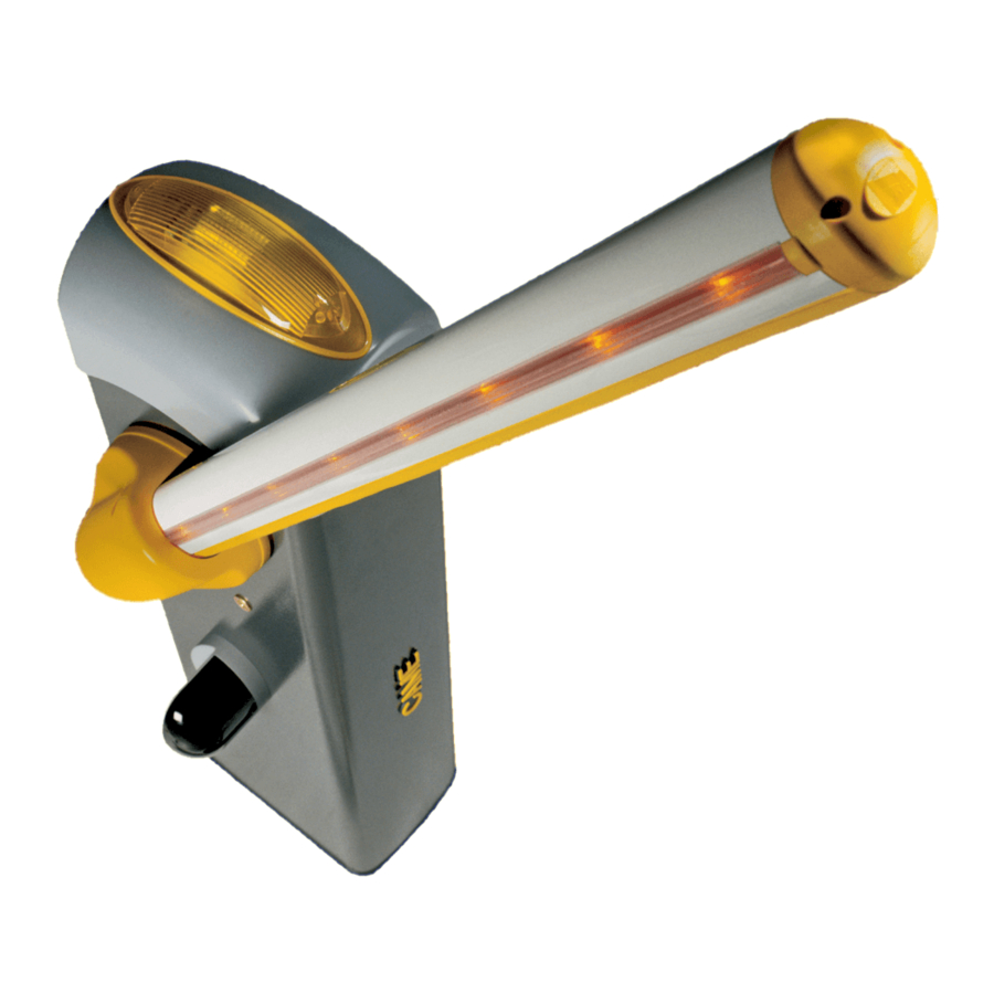
- Page 4 Description of parts 1. Dome 9. Boom setting mechanical stop 2. Motor-shaft plate 10. Lever arm 3. Mid plate 11. Gearmotor with encoder 4. Boom-attachment cover 12. Inspection hatch 5. Protective casing shear proof 13. Anchoring bracket 6. Cabinet 14. Anchoring plate 7.
- Page 5 GENERAL INSTRUCTIONS FOR INSTALLING ⚠ Only skilled, qualified staff must install this product. Important! Using original CAME control and safety devices and accessories ensures easy installation and system maintenance. Preliminary checks ⚠ Before beginning, do the following: • make sure the plate is anchored to a solid spot;...
-
Page 6: Installation
INSTALLATION ⚠ The following illustrations are mere examples. Consider that the space available where to fit the barrier and accessories will vary depending on the area where it is installed. It is up to each installer to select the most suitable solution. ⚠ ... - Page 7 Fill the hole with earth around the concrete block. Remove the nut and washer from the bolts Fit the electric cables into the tubes so that they come out about 600 mm. Preparing the barrier Remove the screws from the dome, fit the key into the lock and turn it counter clockwise . Lift the dome and remove the inspection hatch .
- Page 8 Installing the barrier The cabinet should be installed with the inspection hatch on the most accessible side to make any adjusting easier. Place the cabinet onto the anchoring plate and fasten it using nuts and washers. Assemble the boom-attaching cover, the mid plate and motor-shaft plate with a screw. Leave the screw loose to then facilitate fitting the boom. ⚠...
- Page 9 Fit the boom into the boom-attachment cover and fasten it using the screws. UNI5931 M8x12 UNI5931 M8x20 Cut the groove cover profiles to measure, and fit them into the grooves on both sides of the boom . Fit the rubber anti-shock profile into the boom and cut off any excess . Fasten the endcap using the screws .
- Page 10 Balancing the boom Before balancing the boom, check on the table below for congruences between the chosen spring, accessories and passage clearance. PASSAGE CLEARANCE 8(max 3.75 m) Spring 001G02040 Ø 40 mm Spring 001G04060 Ø 50 mm Spring 001G06080 Ø 55 mm BOOM LENGTH (m) 1,5 ÷...
- Page 11 Hook the eyelet rod to the anchoring rod . Release the gearmotor and manually turn the spring to increase or reduce traction . The boom should stabilize at 45°. Fasten the counter nut and lock the gearmotor again. Check the proper working state of the spring. With the boom raised vertically the spring is not taut.
-
Page 12: Electrical Connections
ELECTRICAL CONNECTIONS ⚠ Warning! Before working on the control panel, cut off the main current supply and, if present, remove any batteries. Power supply to control panel and control devices: 24 V AC/DC. Functions on input and output contacts and time and user management details, are set up and viewable on the control panel's display.All connections are quick-fuse protected. -
Page 13: Power Supply
Power supply Transformer Terminals for powering up accessories: - a 24 V AC normally; - a 24 V DC when the emergency batteries are operating; Overall allowed power: 40 W 24V 0 THERMAL 10 11 E1 E6 230 V AC, 50/60 Hz Eyelet with screw and washer for ground connection Factory wiring... -
Page 14: Command And Control Devices
Command and control devices Black Transponder or card reader Blue White Keypad selector OPEN-CLOSE-INVERT function (step-step) from control device (NO contact). ONLY CLOSE function from control device (NO contact). Warning: in MAINTAINED ACTION mode, the control device must be connected to 2-4. Warning! OPEN ONLY function from control device with NO contact. - Page 15 Warning devices Barrier indicator light (contact rated for: 24 V AC - 3 W max). It warns of the barrier status, see function F 10. Luminous cord (Contact rated for: 24 V AC - 32 W max). If flashes during the boom's opening and closing phases, see function F 15. Flashing dome light (Contact rated for: 24 V AC - 25 W max).
- Page 16 Photocell's safety connection DIR / DELTA S Upon each open or close command, the board verifies that the safety systems work. Any malfunction inhibits any command. Select, from Function F 5, on which inputs to activate. DELTA FUSIBILE 200m A 10 2 T X C 10 11 E1 E6 Rx Tx 1 2 3 3P 4 5 7 CX CY...
- Page 17 Establishing the endstop points Close the inspection hatch and power up the system. Activate the barrier to check whether the boom is parallel to the road surface when closed and at about 89° when open. ⚠ The boom's opening and closing maneuvers must be performed with the inspection hatch closed. To correct the boom's vertical position: - lower the boom;...
- Page 18 PROGRAMMING ⚠ During programming, the barrier must not be moving. Description of programming commands Display S1 GND The ENTER key is for: The ESC button is for: - entering menus; - exiting menus; - confirming or memorizing set values. - deleting changes. The <...
- Page 19 Functions map Total stop function (1-2) Function associated to input CX Function associated to input CY Safety test function Maintained action function Obstruction detection with motor idle function F 10 Warning light function F 11 Encoder exclusion F 14 Sensor type selection function F 15 Intermittent luminous cord function F 18...
- Page 20 Safety test 0 = Deactivated (default) / 1 = CX / 2 = CY / 3 = CX+CY After every opening or closing command, the board will check whether the photocells are working properly. Maintained action 0 = Deactivated (default) / 1 = Activated The barrier opens and closes by keeping one button pressed.
- Page 21 F 30 Opening slow-down speed 15 = Minimum speed / … / 40 = Maximum speed Setting the boom's opening slow-down speed, calculated as a percentage. ⚠ Warning: the speed parameter fi elds vary depending on the type of boom: - for jointed booms of 2 m, set the slow-down speed percentage to between 20 and 40;...
-
Page 22: Motor Test
U 1 Entering a user 1 = Step-step command (open-close) / 2 = Sequential command (open-stop-close-stop) / 3 = Open only command / 4 = Partial command / 5 = contact B1-B2 output Up to a maximum of 25 users can be entered and each can be associated to a function of choice among those available. Entering is done via transmitter or other control device (see ENTERING USERS AND ASSOCIATED COMMANDS). -
Page 23: Travel Calibration
Travel calibration Before doing a travel calibration, establish the boom type, check that the boom is balanced and that the maneuvering area is free of obstructions. Important! While calibrating, all of the safety devices will be disabled excluding the TOTAL STOP one. 1. - Page 24 When entering/deleting users, the fl ashing numbers that appear, are numbers that can be used for other users you may wish to enter (maximum 25 users). Entering a user with an associated command User Associated command 1. Select U 1. Press ENTER to confirm.
-
Page 25: Final Operations
Memory Roll Card To memorize user data and configure the system, to then reuse them with another control board even on another system. Memory roll FINAL OPERATIONS When you done with the electrical connections and setting up, fit the control panel cover and fasten it with the screws . Replace the inspection hatch and the dome . - Page 26 PAIRED CONNECTION Important! Start by doing the following to both operators: - fi t the RSE card (with DIP switches sent to OFF) onto the control panel connector of both barriers. Connect the two control panels with a CAT 5 type cable (maximum 1,000 m) to terminals A-A / B-B / GND-GND / read the CONNECTIONS FOR PAIRED OR ALTERNATE OPERATION paragraph.
-
Page 27: Alternate Connection
ALTERNATE CONNECTION Important! Start by performing the following procedures on both operators: - fi t the RSE card (with DIP switches sent to OFF) onto the control panel connector of both barriers. Connect the two control panels with a CAT 5 type cable (maximum 1,000 m) to terminals A-A / B-B / GND-GND / read the CONNECTIONS FOR PAIRED OR ALTERNATE OPERATION paragraph. -
Page 28: Error Message
ERROR MESSAGE The error messages appear on display and are notified by LEDs The boom travel calibration was interrupted by the activation of the STOP button. Encoder is broken. Services test error. Insufficient working time Maximum number of obstructions detected. Overheating transformer / open inspection hatch / released boom. -
Page 29: Maintenance Log
MAINTENANCE LOG Periodic maintenance ☞ Before doing any maintenance, cut off the power supply, to prevent any hazardous situations caused by accidental boom movements. Periodic maintenance log kept by users (every six months) Date Notes Signature... - Page 30 Extraordinary maintenance ⚠ The following table is for logging any extraordinary maintenance jobs, repairs and improvements performed by specialized contractors. Any extraordinary maintenance jobs must be done only by specialized technicians. Extraordinary maintenance log Fitter's stamp Name of operator Job performed on (date) Technician's signature Requester's signature...
-
Page 31: Dismantling And Disposal
☞ CAME CANCELLI AUTOMATICI S.p.A. employs a certified Environmental Management System at its premises, compliant with the UNI EN ISO 14001 standard to ensure the environment is safeguarded. Please continue safeguarding the environment. At CAME we consider it one of the fundamentals of our operating and market strategies. Simply follow these brief disposal guidelines:... - Page 32 Came S.p.A. Came S.p.A. Via Martiri Della Libertà, 15 Via Cornia, 1/b - 1/c 31030 Dosson di Casier Dosson di Casier 33079 Sesto al Reghena Sesto al Reghena Treviso Treviso - Italy Pordenone Pordenone - Italy (+39) 0422 4940 (+39) 0434 698111...
Need help?
Do you have a question about the G4040E and is the answer not in the manual?
Questions and answers