Jungheinrich DFG 316s Operating Instructions Manual
Hide thumbs
Also See for DFG 316s:
- Operating instructions manual (15 pages) ,
- Operating instructions manual (119 pages)

Related Manuals for Jungheinrich DFG 316s


Summary of Contents for Jungheinrich DFG 316s
- Page 1 DFG/TFG 316s/320s 09.09 - Operating instructions 51123193 05.10 DFG 316s DFG 320s TFG 316s TFG 320s ö J UNGHEINRICH...
- Page 2 Declaration of Conformity Jungheinrich AG, Am Stadtrand 35, D-22047 Hamburg Manufacturer or his authorized representative in the Community Type Option Serial No. Year of construction DFG 316s DFG 320s TFG 316s TFG 320s Additional information Authorised signatory Date G EU Declaration of Conformity...
- Page 4 Our trucks are subject to ongoing development. Jungheinrich reserves the right to alter the design, equipment and technical features of the system. No guarantee of particular features of the truck should therefore be assumed from the present operating instructions.
- Page 5 Jungheinrich Aktiengesellschaft Am Stadtrand 35 22047 Hamburg - Germany Tel: +49 (0) 40/6948-0 www.jungheinrich.com...
-
Page 6: Table Of Contents
Table of contents Correct Use and Application ........... General....................Correct application................... Approved application conditions.............. Proprietor responsibilities ................ Adding attachments and/or accessories..........Truck Description ..............Application ....................Truck models and rated capacity............. Assemblies and Functional Description........... Assembly Overview ................. Functional Description ................Technical Specifications ................ - Page 7 Fuelling the Truck..............General....................Safety regulations for handling diesel fuel and LPG........ Gas system relief valve ................Adding diesel ................... Fuelling ....................Fuelling with fuel containers ..............LPG containers..................LPG bottles....................Liquid gas tank ..................Fuel level indicator................... Display unit ....................Level indicator for LPG bottles (o) ............
- Page 8 Panel door ....................108 Operator position extension..............108 Heating and air conditioning system............109 Driver’s seat heating / backrest extension ..........112 Removable load backrest ................ 113 6.10 Lift cutout override ................... 113 6.11 Sideshift Centre Position ................. 114 6.12 Fire extinguisher ..................114 6.13 Rockinger coupling with hand lever or remote control......
-
Page 10: A Correct Use And Application
A Correct Use and Application General The industrial truck described in the present operating instructions is designed for lifting, lowering and transporting load units. It must be used, operated and serviced in accordance with the present instructions. Any other type of use is beyond the scope of application and can result in damage to personnel, the industrial truck or property. -
Page 11: Approved Application Conditions
Approved application conditions DANGER! Do not exceed the permissible surface and spot load limits on the travel routes. At blind spots get a second person to assist. The driver must ensure that the loading ramp / bridge cannot move or come loose during loading / unloading. -
Page 12: Proprietor Responsibilities
Proprietor responsibilities For the purposes of the present operating instructions the “proprietor” is defined as any natural or legal person who either uses the industrial truck himself, or on whose behalf it is used. In special cases (e.g. leasing or renting) the proprietor is considered the person who, in accordance with existing contractual agreements between the owner and user of the industrial truck, is charged with operational duties. -
Page 14: B Truck Description
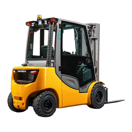
B Truck Description Application The DFG/TFG 316s/320s is a four-wheel IC motor sit-down forklift truck. The DFG series are diesel engine trucks, while the TFG series are fitted with a petrol engine for LPG operation. The DFG/TFG 316s/320s is a cantilever counterbalanced truck which can lift, transport and deposit loads using the load handler attached in front. -
Page 15: Assemblies And Functional Description
Assemblies and Functional Description Assembly Overview Item Description Item Description 1 t Driver's seat 9 t Drive 2 t Overhead guard 10 t Emergency Disconnect switch 3 t Steering wheel 11 t Engine bonnet 4 t Mast 12 t Steer axle 5 t Fork carriage 13 t Counterweight 6 t Fork tines... -
Page 16: Functional Description
Functional Description Chassis The chassis, in conjunction with the counterweight, forms the supporting base structure of the truck. It is used to support the main components. The hydraulic oil reservoir is integrated on the right-hand side and the fuel tank for the DFG series is on the left side in the chassis. - Page 17 Drive system and brakes Both drive wheels are powered by individual hydraulic motors which in turn are driven by a hydraulic pump. Forward/reverse or neutral can be set with the travel direction switch on the control panel (7). The truck brakes to a halt via the hydraulic motors, keeping energy consumption to a minimum.
-
Page 18: Technical Specifications
Values indicated with *) may vary, depending on the types of equipment used (e.g. mast, cabin, tyres etc.). Technical data specified in accordance with VDI 2198. Technical modifications and additions reserved. Performance data Preglow relay (DFG 316s-320s) Description DFG 316s DFG 320s Capacity where... - Page 19 TFG 316s-320s Description TFG 316s TFG 320s Capacity 1600 2000 (where C = 500 mm) Load centre Travel speed * w. / 19.5/19.5 19.5/19.5 km/h w.o. load Lift speed, w. / w.o. load 0.60/0.62 0.60/0.62 Lower speed, w. / w. o. 0.54/0.57 0.54/0.57 load...
-
Page 20: Dimensions
Dimensions DFG/TFG 316s-320s Hydrostatic Jungheinrich Manufacturer's name / type DFG/TFG 316s- DFG/TFG 316s- 320s 320s a/2 Safety distance Mast height retracted* 2185 2185 Free lift* Lift* 3300 3300 Mast height extended* 3920 3920 Overhead guard height* 2145 2145 Seat height... -
Page 22: Weights
Weights All dimensions in kg. DFG 316s DFG 320s TFG 316s TFG 320s Truck weight* 2800 3100 2800 3100 Axle load, w.o. load front/rear* 1340 / 1350 / 1330 / 1340 / 1460 1750 1470 1760 Axle load, w. load front/rear*... -
Page 23: Tyre Type
9.0 Torque NM *) The models listed in the table correspond to the standard version. Other tyres can be used depending on the truck's equipment. Engine Data Engine - DFG 316s/320s Description DFG 316s DFG 320s Cylinder/cubic capacity 4 / 1896 4 / 1896 cm³... -
Page 24: En Norms
EN norms Noise emission level – DFG 316/320: 77dB (A)* – TFG 316/320: 77 dB(A)* *+/- 3 dB(A) depending on the truck's equipment according to test procedure to ANSI/ITSDF B56.11.5. The noise emission level is calculated in accordance with standard procedures and takes into account the noise level when travelling, lifting and when idle. -
Page 25: Conditions Of Use
Conditions of use Ambient temperature – operating at -20 to 40°C Special equipment and authorisation are required if the truck is to be constantly used in conditions of extreme temperature or air humidity fluctuations. Electrical requirements The manufacturer certifies compliance with the requirements for the design and manufacture of electrical equipment, according to EN 1175 "Industrial Truck Safety - Electrical Requirements", provided the truck is used according to its purpose. -
Page 26: Identification Points And Data Plates
Identification points and data plates Warnings and notices such as capacity charts, strap points and data plates must be legible at all times. Replace if necessary. - Page 27 Item Description Do not travel with raised load or mast forward tilt with raised load Strap points for crane lifting Data plate Noise level “Do not carry passengers” warning Fuel Wear seat belt Serial number, engraved in chassis below the engine bonnet Jack contact points Do not step onto or beneath the load, risk of trapping with moving mast Maximum body size (o)
-
Page 28: Data Plate
Data plate Item Description Item Description Type Year of manufacture Serial number Load centre (mm) Rated capacity (kg) Output Output Manufacturer Net weight in kg Manufacturer’s logo Option For queries regarding the truck or ordering spare parts always quote the truck serial number (35). -
Page 29: Truck Capacity Plate
Truck capacity plate CAUTION! Accident risk from fork replacement If you replace the forks with ones that differ from the originals, the capacity will change. When replacing the forks you must attach an additional capacity plate to the truck. Trucks supplied without forks are given a capacity plate for standard forks (length: 1150 mm). -
Page 30: Attachment Capacity Plate
Attachment capacity plate The attachment capacity plate is next to the truck's capacity plate and gives the truck’s capacity Q [in kg] in conjunction with the respective attachment. The serial number for the attachment indicated on the capacity plate must match the data plate of the attachment. -
Page 32: C Transport And Commissioning
C Transport and Commissioning Transport Transport can be carried out in two different ways, depending on the height of the mast and the local conditions. – Vertically, with the mast assembled (for low heights) – Vertically, with the mast dismantled (for large heights), all mechanical connections and hydraulic lines between the basic truck and the mast separated. -
Page 33: Lifting The Truck By Crane
Lifting the truck by crane CAUTION! The mast can get damaged Loading by crane is only intended for the initial transport before the truck is used for the first time. Loading must be carried out by specially trained staff in accordance with recommendations contained in Guidelines VDI 2700 and VDI 2703 DANGER! Crane slings can tear, resulting in accidents... -
Page 34: Loading With Another Industrial Truck
Loading with another industrial truck WARNING! The truck can be damaged The truck to be loaded can get damaged when loading with another industrial truck. Only trained specialist personnel should load the truck. Use only trucks with sufficient capacity for loading. Only for loading and unloading. -
Page 35: Securing The Truck During Transport
Securing the truck during transport WARNING! Accidental movement during transport Improper fastening of the truck and mast during transport can result in serious accidents. Loading must be carried out by specially trained staff in accordance with recommendations contained in Guidelines VDI 2700 and VDI 2703 In each case correct measurements must be made and appropriate safety measures adopted. -
Page 36: Using The Truck For The First Time
Using the Truck for the First Time Safety Instructions for Assembly and Commissioning WARNING! Accident risk from incorrect assembly The assembly of the truck at the application site, commissioning and driver training must only be performed by the manufacturer's customer service representatives who have been specially trained for these tasks. -
Page 38: D Fuelling The Truck
D Fuelling the Truck General Safety regulations for handling diesel fuel and LPG WARNING! An unsecured truck can cause accidents The truck can suddenly start to move. Before filling up or replacing the LPG bottle, park the truck securely, Siehe “Parking the truck securely”... - Page 39 NOTE Fuel can cause environmental damage Bind any spilled diesel fuel with suitable methods. Then dispose of the diesel and fuel filter in accordance with environmental regulations. Fuel filling and LPG bottle replacement personnel Personnel filling the trucks or replacing LPG bottles must have sufficient knowledge of the nature of fuels to ensure safe operation.
-
Page 40: Gas System Relief Valve
Gas system relief valve LPG powered trucks are fitted with a relief valve. This is located on the rear cover next to the gas bottle. – In the event of a fault the pressure in the gas system is restricted to a maximum level. The relief valve is fitted with a plastic cover (50). -
Page 41: Adding Diesel
NOTE Fuelling must always be performed in designated areas by trained and authorised personnel. NOTE Capacity: DFG 316s/320s = 50 l. Use only DIN EN 590 diesel with a certain rating above 51. 2.1.1 Fuelling the tank system Procedure • Park the truck securely before fuelling, (see "Parking the truck securely"... -
Page 42: Fuelling With Fuel Containers
Fuelling with fuel containers Procedure • Unscrew the tank cap (51) and open the fuel container. • Fit the outlet pipe onto the fuel container. • Insert the outlet pipe into the open tank filler neck. • Make sure the fuel container and outlet pipe are connected tightly to each other. -
Page 43: Lpg Containers
LPG containers Only use liquid gas that complies with DIN 51622 or comparable national regulations. LPG bottles DANGER! Risk of explosion The LPG bottle must only be replaced at designated areas by trained and authorised personnel. CAUTION! Using unsuitable LPG bottles can cause accidents. Use only approved LPG bottles. - Page 44 Remove the LPG bottle CAUTION! The connection has a left thread Procedure • Unscrew the union nut (53) while holding against the handle (55). • Remove the hose (56) and immediately screw the valve cap onto the empty LPG bottle. •...
- Page 45 3.1.2 Operating with two LPG bottles WARNING! Visibility is restricted when the truck reverses. When using two LPG bottles the truck must be fitted with a functional camera system for reversing. External mirrors must also be fitted on either side of the truck. Operating the twin bottle system NOTE Use the additional valve (61) on the...
-
Page 46: Liquid Gas Tank
Liquid gas tank Refillable liquid gas tanks contain a dispensing valve (66), a filling stop valve (64), a relief valve (65) and a display (63). Filling refillable liquid gas tanks (optional equipment). Requirements – Note guidelines regulations concerning the filling of LPG bottles on the LPG pump. -
Page 47: Fuel Level Indicator
Fuel level indicator Display unit The fuel level indicator (68) shows the fuel level (only on DFG or TFG with gas tank). If “R” appears in the display (68) the tank must be topped up. The warning light (69) will also flash and a warning sounds. km/h Level indicator for LPG bottles (o) When the fuel indicator (67) and warning light (69) with additional warning sound light... -
Page 48: E Operation
E Operation Safety Regulations for the Operation of the Forklift Truck Driver authorisation The truck may only be used by suitably trained personnel, who have demonstrated to the proprietor or his representative that they can drive and handle loads and have been authorised to operate the truck by the proprietor or his representative. - Page 49 Hazardous area WARNING! Risk of accidents / injury in the hazardous area of the truck The hazardous area is defined as the area in which a person is at risk due to truck movement, lifting operations, the load handler (e.g. forks or attachments) or the load itself.
-
Page 50: Displays And Controls
Displays and Controls Doppelpedalsteuerung Einzelpedalsteuerung Solopilot Multipilot... - Page 51 Item Control / Function Display o The truck reverses when actuated. Provides “Reverse” accelerator twin pedal control infinite control of travel speed. t Infinite travel speed control. Accelerator pedal o The truck travels forward when actuated. “Forward” accelerator twin pedal control Provides infinite control of travel speed.
- Page 52 Item Control / Function Display t Selects travel direction / neutral position. Travel direction switch (not available with dual pedal control) t Lever for operating the hydraulic functions. Lever t Activates an audible warning. Horn o Activates the additional hydraulic functions Additional hydraulic function release button or hydraulics that require...
-
Page 53: Control Panel With Display Unit
Control panel with display unit The control panel display unit shows the operating data, the battery charge, the service hours and error details and information. Pictograms in the left top section of the control panel act as warning indicators. km/h... - Page 54 Item Control / Function Display – Lights up a single time to indicate that the fuel supply is too low. Lights up in conjunction with err xx xxx or inf WARNING xx xxx to indicate a fault or information. – A warning signal sounds Air filter control –...
- Page 55 Item Control / Function Display Service display – Set service interval exceeded (1000 service hours) or carry out FEM test after 12 months (display flashes), must be set by the manufacturer’s customer service department. Pre-heat indicator – Engine is preheated (DFG only). lamp –...
-
Page 56: Control Panel Buttons
Control panel buttons km/h Item Control / Display Function t Moves up a level in the travel program* Program selector list. t Moves down a level in the travel program* Program selector list. t Applies/releases the parking brake Parking brake o –... - Page 57 Item Control / Display Function o – Switches window wipers on and off, Front windscreen wiper interval setting. – Press 1x > intermittent, – Press 2x > fast, – 3x > off o Switches warning indicator system on and Warning indicator system off.
- Page 58 performance for high throughput levels). If necessary the operating programs can also be adapted or restricted to suit the customer. Please contact the manufacturer’s service department.
-
Page 59: Display
Display km/h DFG fuel supply display Graphic illustration of the fuel supply. TFG with gas tank t Operating program display 122 Operating program display – Displays the travel program in use t Shows the time. 123 Time t Error display: Service hours / error display: –... -
Page 60: Preparing The Truck For Operation
Preparing the Truck for Operation Checks and operations to be performed before starting daily operation WARNING! Damage and other truck or attachment (special equipment) defects can result in accidents. If damage or other truck or attachment (special equipment) defects are discovered during the following checks, the truck must be taken out of service until it has been repaired. - Page 61 CAUTION! Checking the accelerator pedal The accelerator pedal should only be checked when the parking brake is applied and the engine is idle. Checks after daily operation Procedure • Visually inspect the entire truck (in particular wheels, wheel bolts and load handler) for damage.
-
Page 62: Entry And Exit
Entry and exit Procedure • Open the cab door (o) • To enter and exit the cab, hold onto the handle (128). An additional step is provided for the driver position extension (o) Trucks with reduced headroom X (o) WARNING! An unsuitable workplace can damage your health Failure to observe the recommended... -
Page 63: Setting Up The Operator Position
Setting up the operator position WARNING! Accident risk Do not adjust the driver’s seat while travelling. Procedure • Before starting to travel, adjust the driver’s seat, steering column and armrest (if necessary) so that all the controls are within reach and can be applied without having to strain. - Page 64 Adjusting the driver's weight NOTE To achieve optimal seat cushioning the driver’s seat must be adapted to the driver’s weight. Set the driver's weight when the seat is occupied. Procedure • Move the lever (129) as far as it will go in the arrow direction until you reach the required weight on the scales.
- Page 65 Driver’s seat with pneumatic weight adjustment (MSG 75) ( Procedure • Pull the weight adjustment lever (129) up to set the seat to a higher weight. • Push the weight adjustment lever (129) down to set the seat to a lower weight. The driver's weight is correct when the arrow is in the middle of the display window (130).
- Page 66 3.4.2 Adjusting the steering wheel / steering column Individual steering wheel position The steering wheel can be height- and tilt-adjusted to suit the operator. Procedure • Pull the steering wheel adjusting lever (137) in the direction of the arrow (136). •...
- Page 67 3.4.3 Adjusting the arm rest Horizontal adjustment: Procedure • Undo the clamping screw (139) a few turns. • The armrest can now be moved forward or back. When you have reached the required setting, tighten the clamping screw (139) again; this will lock the armrest in place. Vertical adjustment: Procedure •...
-
Page 68: Seat Belt
Seat Belt DANGER! Travelling without a seat belt increases the risk of injury. If the seat belt is not worn or is modified, personal injury can result. Always put on the seat belt before starting the industrial truck. Do not modify the seat belt. Damaged or non-operational seat belts must be replaced by trained personnel. -
Page 69: Industrial Truck Operation
Industrial Truck Operation Safety regulations for truck operation Travel routes and work areas Only use lanes and routes specifically designated for truck traffic. Unauthorised third parties must stay away from work areas. Loads must only be stored in places specially designated for this purpose. The truck must only be operated in work areas with sufficient lighting to avoid danger to personnel and materials. - Page 70 Prevent liquid loads from sloshing out. Inflammable liquids (e.g. fused metal etc.) may only be transported with suitable auxiliary equipment. Contact your authorized Jungheinrich customer adviser. For safety instructions on the nature of loads to be carried with attachments,(see "Lifting, transporting and depositing loads"...
-
Page 71: Preparing The Truck For Operation
Preparing the truck for operation The truck should only be operated from the driver’s seat. Do not run up the engine idle. engine soon reaches operating temperature at a moderate charge and when the speed alternates. Only fully charge the engine once it has reached operating temperature. - Page 72 4.2.1 Starting procedure for the DFG Procedure • Insert the key in the key switch (79). Set the key switch to “I”. • The pre-heat indicator lamp lights up and goes out automatically as soon as the required pre-heat time (approx.
- Page 73 4.2.2 Starting procedure for the TFG DANGER! Risk of escaping liquid gas if the truck does not start Note the safety regulations governing the handling of liquid gas ((see "Safety regulations for handling diesel fuel and LPG" on page 39)) Close the gas bottle shut-off valve.
-
Page 74: Setting The Time
Setting the time Procedure • To prepare the truck for operation, (see "Preparing the truck for operation" on page 72) km/h • Press the “h/time” (108) and "up" (101) keys simultaneously • The set time appears on the display. The first digit (hour display) will flash. •... -
Page 75: Parking The Truck Securely
Parking the truck securely DANGER! Risk of explosion LPG trucks may only be parked in ground level rooms or higher and providing they are adequately ventilated. They must not be parked near to cellar doors and entry points, hollows, drains, drain inlets or other recesses below the parked truck. WARNING! An unsecured truck can cause accidents Parking the truck on an incline, without the brakes applied or with a raised load / load... -
Page 76: Emergency Disconnect
Emergency Disconnect CAUTION! Accident risk Applying the Emergency Disconnect switch during travel will cause the truck to brake to a halt at maximum force. This may cause the load to slide off the forks. There is a higher risk of accidents and injury! The operation of the Emergency Disconnect button must not be affected by any objects placed in its way. -
Page 77: Travel
Travel WARNING! Improper travel can result in accidents Do not get up from the driver’s seat during travel. Do not drive the truck unless your are wearing a seat belt and the panels and doors are properly locked. Make sure that the travel area is clear. Adapt the travel speed to the conditions of the route, the work area and the load. - Page 78 Neutral locking If the driver leaves the truck without taking it out of gear, the truck will automatically be set to neutral. To resume travel (sitting on the truck) all controls must be deactivated, the travel direction switch must be set to neutral “N” and then the required direction selected.
-
Page 79: Steering
Steering Steering Procedure Very little steering effort is required; you should therefore turn the steering wheel (74) sensitively. • To negotiate a right-hand bend: Turn the steering wheel clockwise according to the required steering radius. • To negotiate a left-hand bend: Turn the steering wheel anti-clockwise according to the required steering radius. - Page 80 4.8.1 Service brake In normal travel mode you brake by throttling back using the accelerator pedal (70,71,72). The truck will brake hydrostatically depending on the travel program. This allows for sensitive metering of the brake force. The parking brake automatically applies as soon as the truck comes to a halt.
- Page 81 4.8.2 Parking brake DANGER! Accident risk The parking brake will hold the truck km/h with maximum load on a clean ground surface, on inclines of up to 15%. Do not park and abandon the truck on an incline. Applying the parking brake during travel will cause the truck to brake to a halt at maximum force.
-
Page 82: Adjusting The Forks
Adjusting the forks WARNING! Trapping hazard There is a trapping hazard when you perform this operation. Wear work gloves and safety shoes. WARNING! Unsecured and incorrectly adjusted forks can cause accidents Before adjusting the forks make sure the retaining bolts (127) are fitted. Adjust the forks so that both forks are equidistant from the outside edge of the fork carriage. -
Page 83: Replacing The Forks
4.10 Replacing the forks WARNING! Risk of injury You can injure your legs when replacing the forks. Never pull the forks towards your body. Always push the forks away from your body. Secure heavy forks with lifting slings and a crane before pushing them down from the fork carriage. -
Page 84: Lifting, Transporting And Depositing Loads
4.11 Lifting, transporting and depositing loads WARNING! Unsecured and incorrectly positioned loads can cause accidents Before lifting a load unit the driver must make sure that it has been correctly palletised and does not exceed the truck’s capacity. Instruct other people to move out of the hazardous area of the truck. Stop working with the truck if people do not leave the hazardous area. - Page 85 NOTE Loads must not be deposited on travel or escape routes, in front of safety mechanisms or operating equipment that must be accessible at all times. Transporting load units Requirements – Load unit correctly lifted. – Load handler lowered for transport (approx. 150 - 200 mm above the ground). –...
-
Page 86: Operating The Lift Mechanism And Integrated Attachments
4.12 Operating the lift mechanism and integrated attachments WARNING! Accident risk when operating the lifting device and integrated attachments Other people can be injured in the truck's hazardous area. The hazardous area is defined as the area in which people are at risk from the truck movement, the load handler, attachments etc. - Page 87 Tilting the mast forward / backward Requirements – To prepare the truck for operation, (see "Preparing the truck for operation" on page 72) Procedure • Pull the Solo-Pilot lever (145) in direction R to tilt the mast back. • Push the Solo-Pilot lever (145) in direction V to tilt the mast forward.
- Page 88 Positioning the forks with an integrated fork adjuster (option) CAUTION! Do not use the fork adjuster to clamp loads. Requirements – To prepare the truck for operation, (see "Preparing the truck for operation" on page 72) Procedure • Press the toggle switch (147) and at the same time pull the Solo Pilot (144) in direction Z: the forks will move towards each other.
- Page 89 4.12.2 Operating the lift mechanism with the Multi Pilot Lifting and lowering Requirements – To prepare the truck for operation, (see "Preparing the truck for operation" on page 72) Procedure • Pull the Multi-Pilot (75) in direction H to raise the load.
- Page 90 Twin operation Requirements – To prepare the truck for operation, (see "Preparing the truck for operation" on page 72) Procedure • To lower the load handler and tilt the mast forward at the same time, push the Multi Pilot forward and to the right.
- Page 91 Positioning the forks with an integrated fork adjuster (option) CAUTION! Do not use the fork adjuster to clamp loads. Requirements – To prepare the truck for operation, (see "Preparing the truck for operation" on page 72) Procedure • Press the (83) button and at the same time turn the Multi Pilot (75) anti-clockwise, the forks will spread apart.
-
Page 92: Safety Instructions For Operating Additional Attachments
4.13 Safety instructions for operating additional attachments Optionally, trucks can be fitted with one or more auxiliary hydraulic functions to operate attachments. The auxiliary hydraulics are indicated with ZH1, ZH2 and ZH3. Auxiliary hydraulic functions for exchangeable equipment are fitted with replacement couplings on the fork carriage. - Page 93 Safety instructions for sideshifter and fork adjuster attachments WARNING! When using multi fork adjusters (multi pallet clamps), restricted visibility and reduced lateral tilt resistance can result in accidents. Adapt the travel speeds to the visibility and load. Make sure you have enough visibility when reversing. Safety instructions for clamping attachments (e.g.
- Page 94 Safety instructions for attachments when transporting suspended loads WARNING! Swinging loads and a reduced residual capacity can result in accidents Adapt the travel speed to the load, less than walking pace. Secure swinging loads for example with lifting slings. Reduce the residual capacity and have it certified by a expert. Safety instructions for using loading buckets as attachments WARNING! Greater mast loading can cause accidents.
-
Page 95: Operating Additional Attachments For The Solo-Pilot
4.14 Operating additional attachments for the SOLO-PILOT WARNING! Incorrect symbols can cause accidents Symbols on controls that do not depict the function of the attachments can cause accidents. Mark the controls with symbols that indicate their function. Specify the attachments’ direction of movement in accordance with ISO 3691-1 so that they match the controls’... - Page 96 4.14.2 Solo Pilot with control of ZH1 and ZH2 hydraulic ports Depending on the attachments used the lever / button (144, 146, 147) is assigned the function of the attachment. Levers that are not required are void. For connections (see "Assembly and hydraulic ports of additional attachments"...
-
Page 97: Operating Additional Attachments For The Multi Pilot
4.15 Operating additional attachments for the Multi Pilot WARNING! Incorrect symbols can cause accidents Symbols on controls that do not depict the function of the attachments can cause accidents. Mark the controls with symbols that indicate their function. Specify the attachments’ direction of movement in accordance with ISO 3691-1 so that they match the controls’... - Page 98 4.15.3 Multi Pilot with control of ZH1, ZH2 and ZH3 hydraulic ports Depending on the attachments used the buttons (148, 149, 83) and the lever (75) are assigned the function of the attachment. Levers that are not required are void. For connections (see "Assembly and hydraulic ports of additional attachments"...
-
Page 99: Assembly And Hydraulic Ports Of Additional Attachments
4.16 Assembly and hydraulic ports of additional attachments WARNING! Incorrectly connected attachments can cause accidents. Attachments with incorrectly connected hydraulic attachments can result in accidents. Attachments must only be assembled and commissioned by trained, specialist personnel. Note the attachment manufacturer’s operating instructions. Before commissioning, check the fasteners are positioned correctly and securely and make sure they are complete. - Page 100 Spilled hydraulic oil must be set using a suitable agent and disposed of in accordance with environmental regulations. If hydraulic oil comes into contact with the skin, wash it off immediately with soap and water. If it comes into contact with the eyes rinse them immediately with flowing water and call for a doctor.
-
Page 101: Towing Trailers
Towing trailers DANGER! Inappropriate speeds and excessive trailer loads can be dangerous If you do not adapt your speed and / or use an excessive trailer load, the truck can pull apart when cornering and braking. The truck should only be used occasionally to tow trailers. The overall weight of the trailer should not exceed the capacity indicated on the capacity plate, (see "Identification points and data plates"... - Page 102 Attaching the trailer CAUTION! Trapping hazard There is a trapping risk when you attach a trailer. Follow the instructions of the coupling manufacturer if using special trailer couplings. Secure the trailer to prevent it from rolling away before coupling it. Do not get caught between the truck and the tiller when coupling the trailer.
-
Page 103: Optional Equipment
Optional equipment Assistance systems The Access, Drive and Lift Control systems help the driver operate the truck with regard to safety regulations, (see "Safety regulations for truck operation" on page 70) " of the present operating instructions. Travel conduct The driver must adapt the travel speed to local conditions. The truck must be driven at slow speed when negotiating bends or narrow passageways, when passing through swing doors and at blind spots. - Page 104 6.1.2 Drive Control This option restricts the travel speed of the truck irrespective of the steer angle. Beyond a factory set lift height (approx. 1.50m) the maximum speed is restricted to walking pace (approx. 3 km/h) and the slow travel indicator is activated. When the mast drops below this height again, the travel speed picks up at reduced acceleration level to the speed set by the accelerator pedal to prevent unexpected sudden acceleration when changing from slow travel to normal travel.
-
Page 105: Steel Cab
Steel cab For trucks fitted with a steel cabin, both doors can be closed. CAUTION! An open door can cause accidents (153) Do not travel with an open door (153). When opening the door make sure there is nobody in the door’s swing range. Always close the door tightly and make sure it is locked. -
Page 106: Automatic / Mechanical Folding Gate
Automatic / mechanical folding gate CAUTION! A faulty folding gate can cause accidents Never use the truck with a non- functional folding gate. Have the folding gate checked by authorised specialist personnel after an accident. Do not modify the folding gate. Always close the folding gate tightly and make sure it is locked. -
Page 107: Panel Door
Panel door CAUTION! An open door can cause accidents (153) Do not travel with an open door (153). When opening the door make sure there is nobody in the door’s swing range. Always close the door tightly and make sure it is locked. Closing the door does not release the driver from his responsibility to wear a seat belt, (see "Seat Belt"... -
Page 108: Heating And Air Conditioning System
Heating and air conditioning system Replacing the air conditioning filter Procedure • Turn the twist off knob (161) anti-clockwise. • Pull the filter cassette (160) out in the direction of the arrow. • Replace the filter • Insert the filter cassette (160) into the heating console (159). - Page 109 6.7.1 Heating Item Description Item Description Body jets 166 Recirculating air flap: Recirculates the air in the Temperature controller 167 Foot compartment jet Fan settings 168 Windscreen jets Air distribution control Heating operation Procedure • Press the switch (164) to switch on the fan. •...
- Page 110 6.7.2 Air conditioning system CAUTION! Extreme temperature differences can affect your health. When using the air conditioning system make sure the temperature is no higher than 6°C more than the outside air temperature. Keep the doors and windows closed when the air conditioning system is switched Do not direct discharge jets at other people.
-
Page 111: Driver's Seat Heating / Backrest Extension
Driver’s seat heating / backrest extension km/h Heating the seat Procedure • Seat heating button (118). • Press the switch (170): 1 = seat heating ON; 0 = seat heating OFF. Adjusting the backrest extension CAUTION! Accident risk when adjusting the backrest during travel Do not adjust the backrest extension while travelling. -
Page 112: Removable Load Backrest
Removable load backrest CAUTION! Trapping hazard and heavy load backrest weight Wear safety gloves and safety shoes when carrying out this operation. Two people are required to remove and attach the load backrest. Load backrest disassembly Procedure • Loosen the screws (171) •... -
Page 113: Sideshift Centre Position
6.11 Sideshift Centre Position Automatic sideshifter centring control Requirements – Checks and operations performed before starting daily operation ((see "Checks and km/h operations to be performed before starting daily operation" on page 61)). – Check automatic sideshifter centring with the function key (108). -
Page 114: Rockinger Coupling With Hand Lever Or Remote Control
6.13 Rockinger coupling with hand lever or remote control Refer to the instructions for towing trailers, (see "Towing trailers" on page 102). CAUTION! Incorrectly coupled trailers can cause accidents Make sure the coupling is engaged securely before starting the truck. The contro pin (175) must be flush with the control sleeve (176). -
Page 115: Camera System
6.14 Camera system CAUTION! Accident risk from hidden work areas The camera system acts as an aid to assist safe operation. Practice travelling and working with the camera system. Align the camera so that the hidden work area can be seen. When using the camera to reverse, the monitor automatically switches on when you engage reverse gear. -
Page 116: Optional Equipment For Working In Dusty Environments
6.15 Optional equipment for working in dusty environments When working in areas with high dust levels (lint, splinters) the truck can be fitted with an optional lint filter on the cooler. CAUTION! Clogged lint filters can cause fires The lint filter must be cleaned regularly according to how much it is clogged. Procedure •... -
Page 117: Control Layout "N
6.17 Control layout “N” WARNING! Ensure there are no other people standing underneath the raised load and driver's cab. Do not stand on the load handler. Do not lift other people on the load handler. Instruct other people to move out of the hazardous area of the truck. Never stand underneath a raised and unsecured load handler / driver's cab. -
Page 118: Troubleshooting
Troubleshooting Troubleshooting This chapter enables the user to identify and rectify basic faults and the effects of incorrect operation. When trying to locate a fault, proceed in the order shown in the table. If, after carrying out the following remedial action, the truck cannot be restored to operation or if a fault in the electronics system is displayed with a corresponding error code, contact the manufacturer’s service department. - Page 119 Operational fault displays NOTE When the overtemperature indicator (90) is lit the performance of the truck automatically reduces to 0% at a steady km/h rate from the point of the temperature limit, as the temperature rises. The truck can still be taken to the nearest workshop. NOTE When the engine oil pressure display (86) is lit the engine must be switched off immediately.
- Page 120 Display Meaning Parking brake released during initialisation – Parking brake must be activated, (see "Release the parking brake." on page 125). Self test interrupted – The truck performs a self-test after the start (tests the controllers and motor). During this time the truck cannot move or lift.
- Page 121 Fault Possible Cause Action Starter does not turn – Battery charge too low. – Check battery charge, charge battery if – Battery connection necessary cable loose or terminals oxidized. – Clean and grease terminals, tighten – Starter motor cable battery connection loose or broken, cable.
- Page 122 Fault Possible Cause Action Engine does not start – Air filter contaminated. – Clean / replace air filter. DFG: Engine does not start – Fuel tank empty, – Fill up with diesel and injection system has bleed the injection suctioned in air. system –...
-
Page 123: Operating The Truck Without Its Own Drive System
Operating the truck without its own drive system 7.2.1 Towing the truck WARNING! Accident risk Other people can be injured if the truck is towed incorrectly. Only use vehicles to tow the truck which have sufficient tow and brake forces for the trailer load without its own braking system. - Page 124 7.2.2 Release the parking brake. WARNING! Uncontrolled truck movement When the brakes are released the truck must be parked securely on a level surface, since the brakes are no longer effective. Do not release the parking brake on slopes or inclines. Apply the brake again when you reach your destination.
- Page 125 7.2.3 Emergency lowering The mast can be lowered manually if a fault occurs in the hydraulic system. WARNING! Lowering the mast can result in injuries Instruct other people to move out of the hazardous area of the truck during emergency lowering. Never stand underneath a raised load handler.
- Page 126 7.2.4 Starting aid WARNING! Danger from overheating Only use an ISO 6722 battery jump lead with fully insulated terminal pliers and a lead diameter of at least 25 mm The jump start connection (190) is located in the main fuse box on the starter battery. Procedure •...
-
Page 128: F Industrial Truck Maintenance
F Industrial Truck Maintenance Operational Safety and Environmental Protection The checks and servicing operations contained in this chapter must be performed in accordance with the intervals as indicated in the servicing checklists. WARNING! Risk of accidents and damage to components Any modification to the truck, in particular the safety mechanisms, is prohibited. -
Page 129: Maintenance Safety Regulations
Maintenance Safety Regulations Maintenance and repair personnel Truck maintenance and repair work must only be carried out by specially trained personnel. A maintenance contract with the manufacturer will ensure trouble-free operation. The manufacturer’s service department has customer service technicians specially trained for these tasks. Lifting and jacking up WARNING! Lifting and jacking up the truck safely... - Page 130 Cleaning CAUTION! Fire hazard The truck must not be cleaned with flammable fluids. If flammable materials are not removed from the engine compartment, they can come into contact with hot components and cause a fire. Carry out all necessary safety measures to prevent sparking before cleaning (e.g. by short-circuiting).
- Page 131 Electrical system CAUTION! Accident risk from Electrical system: Only trained personnel may work on the electrical system. Before working on the electrical system, all precautionary measures must be taken to avoid electrical accidents. The connecting leads on the starter battery must be disassembled to disable it. WARNING! Electric currents can cause accidents Make sure the electrical system is voltage-free before starting work on it.
- Page 132 Tyre type WARNING! The use of tyres that do not match the manufacturer's specifications can result in accidents. The quality of tyres affects the stability and performance of the truck. Uneven wear affects the truck's stability and increases the stopping distance. When replacing tyres make sure the truck is not skewed.
- Page 133 Hydraulic hoses WARNING! Brittle hydraulic hose lines can cause accidents The hoses must be replaced every six years. The manufacturer's customer service department is specially trained to carry out these operations. Comply with the safety regulations for hydraulic hose lines in accordance with BGR 237.
-
Page 134: Servicing And Inspection
The application conditions of an industrial truck have a considerable impact on the wear of the service components. We recommend that a Jungheinrich customer service adviser carries out an application analysis on site to work out specific service intervals to prevent damage due to wear. -
Page 135: Maintenance Checklist
Maintenance checklist DFG Maintenance Checklist Maintenance intervals Standard = t W A B C Brakes 1.1 Test the brakes. Maintenance intervals Standard = t W A B C Electrical system Test the warning and safety devices in accordance with operating instructions. - Page 136 Maintenance intervals Standard = t W A B C Travel 4.6 Check the coolant level and top up if necessary. 4.7 Test the hydraulic fans and check for leaks. 4.8 Check and clean the radiator. 4.9 Check the wheel suspension and attachment. 4.10 Check the tyres for wear and damage.
- Page 137 Maintenance intervals Standard = t W A B C Chassis and Superstructure 5.1 Check chassis and screw connections for damage. 5.2 Check the doors and/or covers. 5.3 Check labels are legible and complete. 5.4 Check the attachment and setting function of the driver's seat. Check the engine compartment for contamination and clean if necessary.
- Page 138 Maintenance intervals Standard = t W A B C Hydraulic Operation Test the hydraulic control and check it is assigned to the correct function. 6.2 Check the hydraulic unit labels are legible and complete. Check the cylinders and piston rods for damage and leaks, and make sure they are secure.
- Page 139 Maintenance intervals Standard = t W A B C Hydraulic Operation Check the attachment is properly secured to the truck and the 6.26 supporting elements. Check bearing points, guides and stops for wear and damage, 6.27 grease and clean these components. 6.28 Check the hydraulic ports and tighten if necessary.
-
Page 140: Tfg Maintenance Checklist
TFG Maintenance Checklist Maintenance intervals Standard = t W A B C Brakes 1.1 Test the brakes. Maintenance intervals Standard = t W A B C Electrical system Test the warning and safety devices in accordance with operating instructions. 2.2 Test the displays and controls. 2.3 Test the lights. - Page 141 Maintenance intervals Standard = t W A B C Travel 4.1 Test the exhaust system and check for leaks and damage. Check the wheel motors and displacement pump for noise and leakage. 4.3 Test the anti-freeze, top up if necessary. 4.4 Replace the radiator fluid and anti-freeze.
- Page 142 Maintenance intervals Standard = t W A B C Chassis and Superstructure 5.1 Check chassis and screw connections for damage. 5.2 Check the doors and/or covers. 5.3 Check labels are legible and complete. 5.4 Check the attachment and setting function of the driver's seat. Check the engine compartment for contamination and clean if necessary.
- Page 143 Maintenance intervals Standard = t W A B C Hydraulic Operation Test the hydraulic control and check it is assigned to the correct function. 6.2 Check the hydraulic unit labels are legible and complete. Check the cylinders and piston rods for damage and leaks, and make sure they are secure.
- Page 144 Maintenance intervals Standard = t W A B C Hydraulic Operation Check the attachment is properly secured to the truck and the 6.26 supporting elements. Check bearing points, guides and stops for wear and damage, 6.27 grease and clean these components. 6.28 Check the hydraulic ports and tighten if necessary.
-
Page 145: Lubricants And Lubrication Schedule
Lubricants and Lubrication Schedule Handling consumables safely Handling consumables Consumables must always be handled correctly. Follow the manufacturer’s instructions. WARNING! Improper handling is hazardous to health, life and the environment Consumables can be flammable. Keep consumables away from hot components and naked flames. Always keep consumables in prescribed containers. - Page 146 Consumables and used parts CAUTION! Consumables and used parts are an environmental hazard Used parts, oils and fuels must be disposed of in accordance with the relevant environmental protection regulations. To change the oil contact the manufacturer's customer service department, who have been specially trained for this task. Note the safety regulations when handling these materials.
-
Page 147: Lubrication Schedule
Lubrication Schedule g Contact surfaces Hydraulic oil drain plug s Grease nipple Coolant filler cap Hydraulic oil filler neck Engine oil filler neck... -
Page 148: Consumables
Consumables Code Order no. Quantit Capaci Description Used for 51037495 40 l Hydraulic system Renolin B46 51037499 50055726 400 gr Grease Mast roller and K-P-2K sideshifter contact surfaces; Steer axle 29201280 0.4 l Chain spray Chains 51073093 4.0 l 4,5l Titan GT 1 Engine oil Longlife III SAE... - Page 149 Coolant specification The quality of the coolant used can have a major impact on the efficiency and service life of the cooling circuit. The recommendations listed below are useful for servicing a good cooling circuit with anti-freeze and/or anti-corrosion. Always use clean, soft water. Do not use distilled water. DANGER! Anti-freeze is poisonous Anti-freeze contains ethylene glycol and other components which can result in...
-
Page 150: Maintenance And Repairs
Maintenance and repairs Preparing the truck for maintenance and repairs All necessary safety measures must be taken to avoid accidents when carrying out maintenance and repairs. The following preparations must be made: Procedure • Park the truck securely, (see "Parking the truck securely"... -
Page 151: Unlocking The Engine Bonnet
Unlocking the engine bonnet Unlocking the engine bonnet Requirements – For trucks with a closed cab open both cabin doors before lifting the engine cover (o). Procedure • Set the steering column to the parking position ((see "Adjusting the steering wheel / steering column"... -
Page 152: Opening The Engine Cover
Opening the engine cover NOTE Opening the engine cover The engine panel can be locked in the 50° and 70° positions. The 50° position is locked by gas pressure spring (195) while the 70° position is locked by gas pressure spring (196). Open the engine cover (11) as far as the 50°... - Page 153 Closing the engine cover Procedure • Raise the engine cover slightly and hold it. • From the 70° stage push in the red lock (197) of the right hand gas pressure spring. The engine cover is unlocked. • Lower the engine cover as far as the 50° stage. •...
-
Page 154: Checking The Wheel Attachments
Checking the wheel attachments. WARNING! Using different tyres can cause accidents The quality of tyres affects the stability and performance of the truck. The diameter of the wheels must differ by no more than 15 mm. Always replace tyres in pairs. After replacing the tyres check the wheel nuts are secure after 10 service hours. -
Page 155: Hydraulic System
Hydraulic system CAUTION! The hydraulic oil is pressurised during operation and is a hazard to health and to the environment. Do not touch pressurised hydraulic lines. Dispose of used oil in accordance with regulations. Store used oil safely until it can be disposed of in accordance with regulations. - Page 156 6.6.1 Checking the hydraulic oil level Requirements – Park the truck on a level surface. – Start the engine and fully raise and lower the mast once. – Switch off the engine. Procedure • Remove the hydraulic oil dipstick (200) from the hole wipe it with a clean cloth and insert it fully again.
- Page 157 6.6.3 Replacing the hydraulic oil filter Procedure • Unscrew the cap of the hydraulic oil filter (201). • Remove the filter from the cover. • Insert a new filter and screw the lid back on. 6.6.4 Replacing the ventilation/discharge filter Procedure •...
-
Page 158: Engine Maintenance
Engine maintenance DANGER! A running engine can be dangerous. There is a high risk of injury when the cover is open and the engine running. Do not reach into moving parts (e.g. fan, belt drive). Truck maintenance and repair work must only be carried out by specially trained personnel who have been authorised by the owner. - Page 159 6.7.2 DFG engine maintenance NOTE Used oil contaminates the environment Dispose of used oil and used engine oil filters in accordance with environmental regulations. CAUTION! Risk of scalding through hot oil. Wear appropriate safety gloves when replacing the oil and oil filter. NOTE When the engine is cold the engine oil can be viscous.
- Page 160 Draining the engine oil Procedure • Remove the floorboard. • Unscrew the filler cap (206). • Thoroughly clean the oil drain plug (205) and around the drain hole. • Unscrew the oil drain plug. • Collect any oil that emerges. •...
- Page 161 NOTE The incorrect amount of oil will damage the engine. After replacing the oil and oil filter carry out a test run and check the oil pressure km/h display (86). Check that the oil drain plug and oil filter housing are tight.
- Page 162 6.7.3 Replacing the fuel filter NOTE Fuel can cause environmental damage Bind any spilled diesel fuel with suitable methods. Then dispose of the diesel and fuel filter accordance with environmental regulations. – Mark the fuel hoses (210) and loosen the clamps (209) from the fuel filter.
- Page 163 6.7.5 TFG engine maintenance NOTE Used oil contaminates the environment Dispose of used oil and used engine oil filters in accordance with environmental regulations. CAUTION! Risk of scalding through hot oil. Wear appropriate safety gloves when replacing the oil and oil filter. NOTE When the engine is cold the engine oil can be viscous.
- Page 164 Draining the engine oil Procedure • Remove the floorboard. • Unscrew the filler cap (206). • Thoroughly clean the oil drain plug (205) and around the drain hole. • Unscrew the oil drain plug. • Collect any oil that emerges. •...
- Page 165 Adding engine oil Procedure • Add fresh engine oil through the filler port (206) in accordance with the consumables table. • Check the engine oil level with the dipstick (204) and top up if necessary, (see "Consumables" on page 149). •...
- Page 166 6.7.7 Check V-belt for damage NOTE A damaged V-belt will result in malfunctions. If the V-belt (213) is not in good condition, first rectify the damage before using the truck. Procedure • Check V-belt (213) cracks, deformation and wear.
- Page 167 6.7.8 Cooling system NOTE Lack of coolant can cause malfunctions The coolant level should be between the “MIN” and “MAX” markings on the expansion vessel. If the coolant is below the MIN marking, this indicates possible leakage in the radiator system. Do not continue using the truck.
- Page 168 Check the coolant concentrate Tools and Material Required – Anti-freeze tester for coolants Procedure • Slowly unscrew the filler cap (218) from the expansion vessel (216). • Check the anti-freeze content of the coolant with an anti-freeze tester. NOTE The incorrect coolant concentration can cause malfunctions If there is insufficient anti-freeze content arrange for trained personnel to restore...
- Page 169 Check the cooler and fan and clean if necessary Procedure • Remove minor contamination from the fan grille (219) with weak suctioned air. CAUTION! Risk of incorrect disassembly/assembly of fan unit Only trained personnel may remove major cooler contamination. • Remove the four mounting screws (220) and washers and place the fan unit to the front.
- Page 170 Replace air filter cartridge Procedure • Undo the 2 mounting clamps (221) and remove the dust collector pot. • Carefully remove the air filter cartridge from the filter housing. Cleaning the filter housing Procedure NOTE A faulty engine can cause malfunctions Do not clean the air filter housing with compressed air.
- Page 171 6.7.10 Heating and air conditioning system (o) Replacing the air conditioning filter Procedure • Turn the twist off knob (161) anti-clockwise. • Pull the filter cassette (160) out in the direction of the arrow. • Replace the filter • Insert the filter cassette (160) into the heating console (159).
-
Page 172: Checking Electrical Fuses
Checking electrical fuses Checking electrical fuses Requirements – Prepare the truck for maintenance and repairs ((see "Preparing the truck for maintenance and repairs" on page 151)). Procedure • Open the rear cover of the truck, (see "Opening the rear panel" on page 151). •... - Page 173 6.8.1 Fuse ratings 5 6 7 8 9 10 11 12 13 14 15 16 17 18 19 20 21 22 23 24 25 26 27 28 29 30 31 32 33 34 35 36 37 38 39 50 51 52 xs 182 xs 180 Item Description...
- Page 174 Item Description Electric circuit Rating (A) o LH dipped lights 5F5.1 o LH dipped lights (set A version) 5 / 3 o not used (pre- 11.09 changeover valve) 9F23 t Fan 4F10 t Armrest terminal 15 F1.1 t Socket 9F26 o Not used o Option relay 1/2K63.1 Option connector XS182/3 engine...
- Page 175 LED optional equipment t= Series equipment o= Optional equipment...
- Page 176 Relay Item Description To protect: Rating o Rear window heating t X contact 9K3.1 o Seat heating t Horn t Engine start with bonnet open t Starter relay t Ignition on – engine not running 9K23 t Ignition on - engine running 9K24 t Engine main relay 9K22...
- Page 177 Item Description To protect: Rating t Preheat (DFG only) 9F18 ECU engine controller (TFG only) o Soot particle filter t Engine ignition off o External air conditioning system 9F20 t Terminal 30 constant positive t Starter relay supply wire F19.4 t Constant positive for engine term.
-
Page 178: Starter Battery
Starter battery Checking the battery condition, acid level* and acid density* *not for maintenance-free batteries CAUTION! Battery acid can be dangerous Battery acid is highly corrosive. Therefore it is essential to avoid contact with battery acid. If clothing, skin or eyes have nevertheless come into contact with battery acid, immediately rinse the affected parts with water. -
Page 179: Exhaust System
6.10 Exhaust system NOTE Check emissions at regular intervals Check the combustion engine exhaust emissions at regular intervals in accordance with national regulations. Black or blue exhaust smoke is an indicator of high emission levels resulting from combustion engine damage or wear. In this case the truck must be examined by specialist personnel. -
Page 180: Seat Belt Maintenance
6.11 Seat belt maintenance Check the safety restraint belt Procedure • Pull out the belt completely and check for fraying • Test the belt buckle and make sure the belt returns correctly into the retractor. • Check the cover for damage. Testing the automatic blocking system Procedure •... -
Page 181: Restoring The Truck To Service After Maintenance And Repairs
6.12 Restoring the truck to service after maintenance and repairs Procedure • Thoroughly clean the truck. • Lubricate the truck according to the lubrication schedule, (see "Lubrication Schedule" on page 148). • Clean the battery, grease the terminals and connect the battery. •... -
Page 182: Decommissioning The Industrial Truck
Decommissioning the industrial truck If the truck is to be out of service for more than a month, e.g. for commercial reasons, it must be stored in a frost-free and dry room. All necessary measures must be taken before, during and after decommissioning as described hereafter. WARNING! Lifting and jacking up the truck safely In order to raise the truck, the lifting gear must only be secured to the points specially... -
Page 183: Prior To Decommissioning
Prior to decommissioning Procedure • Thoroughly clean the truck. • Test the brakes. • Check the hydraulic oil level and replenish if necessary, (see "Checking the hydraulic oil level" on page 157). • Apply a thin layer of oil or grease to any non-painted mechanical components. •... -
Page 184: Restoring The Truck To Service After Decommissioning
Restoring the truck to service after decommissioning Procedure • Thoroughly clean the truck. • Lubricate the truck according to the lubrication schedule, (see "Lubrication Schedule" on page 148). • Clean the battery, grease the terminals and connect the battery. • Charge the battery, (see "Starter battery" on page 179). •... -
Page 185: Safety Tests To Be Performed At Intervals And After Unusual Incidents
Perform a safety check in accordance with national regulations. Jungheinrich recommends the truck be checked to FEM guideline 4.004. The Jungheinrich safety department has trained personnel who are able to carry out inspections. The truck must be inspected at least annually or after any unusual event by a qualified inspector (be sure to comply with national regulations). -
Page 186: Final De-Commissioning, Disposal
Final de-commissioning, disposal Final de-commissioning or disposal of the truck in must be performed in accordance with the regulations of the country of use. In particular, regulations governing the disposal of batteries, fuels and electronic and electrical systems must be observed. The truck must only be disassembled by trained personnel in accordance with the procedures as specified by the manufacturer.
Need help?
Do you have a question about the DFG 316s and is the answer not in the manual?
Questions and answers