Jungheinrich DFG 425s Operating Instructions Manual
Hide thumbs
Also See for DFG 425s:
- Operating instructions manual (15 pages) ,
- Operating instructions manual (229 pages)
Table of Contents
Advertisement
Advertisement
Table of Contents

Related Manuals for Jungheinrich DFG 425s


Summary of Contents for Jungheinrich DFG 425s
- Page 1 DFG/TFG 425s / 435s 10.07- Operating Instructions 51077936 01.09...
- Page 2 Used to indicate standard equipment. Used to indicate optional equipment. Our trucks are subject to ongoing development. Jungheinrich reserves the right to alter the design, equipment and technical features of the truck. No guarantee of particular features of the truck should therefore be inferred from the present operating instructions.
-
Page 4: Table Of Contents
Index Correct Application Truck Description Application ................... B 1 Assemblies and Functional Description ..........B 2 Truck ....................B 3 Standard Version Specifications ............B 5 Performance Data DFG ..............B 5 TFG performance data ................ B 5 Dimensions DFG ................. B 7 TFG dimensions .................. - Page 5 Operational Fault Displays ..............E 9 Heating operation ................E 10 Solopilot/Multipilot ................E 11 Travel direction switch ................. E 12 Neutral locking ..................E 12 Twin pedal operation ................E 12 Horn ....................E 12 Starting up the truck ................E 13 Daily checks and operations to be performed before starting work ..
- Page 6 Additing coolant ................... F 21 Cleaning/replacing the air filter cartridge ..........F 22 6.10 Checking the wheel attachment and air pressure ....... F 23 6.11 Replacing the hydraulic oil filter ............F 24 6.12 Replacing the hydraulic reservoir ventilation/discharge filter ....F 24 6.13 Checking electrical fuses ..............
-
Page 8: A Correct Application
A Correct Application The “Guidelines for the Correct Use and Application of Industrial Trucks” (VDMA) are supplied with the truck. The guidelines form part of these operating instructions and must be observed. National regulations apply in full. It must be used, operated and serviced in accordance with the present instructions. Any other type of use is beyond the scope of application and can result in damage to personnel, the industrial truck or property. -
Page 10: B Truck Description
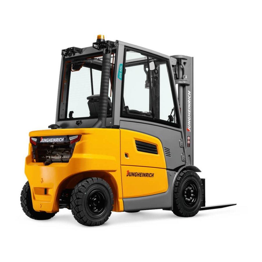
B Truck Description Application The DFG/TFG series trucks are 4-wheel sit-down IC engine forklifts. The DFG series are diesel engine trucks, while the TFG series are fitted with a petrol engine for LPG operation. The DFG/TFG 425-435 is equipped with a hydrostatic drive system. The IC engine drives a high pressure pump for the hydraulic functions and two hydraulic motors to drive wheels. -
Page 11: Assemblies And Functional Description
Assemblies and Functional Description Item Description Item Description t Driver's seat t Fork carriage t Steering column 10 t Drive axle t Dashboard 11 t Engine cover t Overhead guard 12 t Steering axle t Mast 13 t Trailer coupling t Lift cylinder 14 t Counterweight t Load chain... -
Page 12: Truck
Truck Chassis/Superstructure: A rigid chassis which protects the units and controls, pro- vides the truck with maximum static safety. An engine cover (11) that can be locked in the 50° and 70° positions aids service and repair work. The hydraulic oil reservoir for both series is on the right hand side while the fuel tank for the DFG series is housed on the left hand side. - Page 13 Electrical System: The 12 volt system consists of a starter battery and a threephase generator with integrated controller. A repeat start block prevents incorrect operation during start-up and a safety switch ensures the engine can only start when the travel direction switch is in neutral.
-
Page 14: Standard Version Specifications
Standard Version Specifications Technical specification details in accordance with VDI 2198. Technical modifications and additions reserved. Performance Data DFG Model DFG 425s DFG 430s DFG 435s Q Capacity 2500 3000 3500 C Load centre of gravity Travel speed w / w.o. load 19.6/19.6... -
Page 16: Dimensions Dfg
Dimensions DFG Model DFG 425s DFG 430s DFG 435s a/2 Safety distance Mast height (retracted) 2315 2333 2433 Free lift Lift 3300 3300 3300 Mast height (extended) 3910 4070 4083 Overhead guard height 2220 2238 2238 Seat height 1058 1076 1076 α... -
Page 18: Tfg Dimensions
TFG dimensions Model TFG 425s TFG 430s TFG 435s a/2 Safety distance Mast height (retracted) 2315 2333 2433 Free lift Lift 3300 3300 3300 Mast height (extended) 3910 4070 4083 Overhead guard height 2220 2238 2238 Seat height 1058 1076 1076 α... -
Page 19: Engine Data
6.50 x 10 6.50 x 10 6.50 x 10 Wheels, number front/rear 2x/2 2x/2 2x/2 (x = driven) Permissible tyres: See also Chapter F “Industrial Truck Maintenance”, Section 2. Please contact your Jungheinrich customer adviser if you have any queries. B 10... -
Page 20: Mast Versions
Mast Versions DFG/TFG 425s Model Telescopic Duplex mast (ZZ) Triplex Mast (DZ) mast (ZT) Height 2115-3765 2080-2930 2080-3080 Free lift 1480-2330 1480-2480 Lift 2900-6000 2900-4500 4400-7000 Max. height 3510-6610 3500-5100 5000-7600 DFG/TFG 430s Model Telescopic Duplex mast (ZZ) Triplex Mast (DZ) mast (ZT) Height 2133-3783... -
Page 21: En Norms
EN norms Noise level: 75 dB(A) +/- 3dB (depending on tolerances and features) in accordance with EN 12053 as harmonized with ISO 4871. The noise emission level is calculated in accordance with standard procedures and takes into account the noise level when travelling, lifting and when idle. The noise lev- el is measured at the driver’s ear. -
Page 22: Identification Points And Data Plates
Identification points and data plates (mm) Q (kg) D (mm) (mm) Q (kg) D (mm) Item Model Attention: Read operating instructions. “Travel with raised load prohibited” / “Mast forward tilt with raised load prohibited” warning "Wear Seat Belt" decal Strap points for crane lifting “Procedure when truck in danger of tipover”... -
Page 23: Truck Data Plate
Truck data plate Item Model Item Model Model Manufacturer’s logo Serial no. Net weight Rated capacity (kg) Load centre of gravity (mm) Output (kW) Year of manufacture Manufacturer Option For queries regarding the truck or ordering spare parts always quote the truck serial number (31). -
Page 24: Attachment Load Chart
The arrow shape markings (41 and 42) on the inner and outer masts show the driver when the prescribed lift limits have been reached. Attachment load chart The attachment load chart gives the truck’s capacity Q in combination with the re- spective attachment in kg. - Page 25 B 16...
-
Page 26: C Transport And Commissioning
C Transport and Commissioning Transport Transport can be carried out in two different ways, depending on the height of the mast and the local conditions. – Vertically, with the mast assembled (for low heights) – Vertically, with the mast dismantled (for large heights), all hydraulic lines between the basic truck and the mast separated. -
Page 27: Securing The Truck During Transport
Securing the truck during transport The truck must be securely fastened when being transported on a lorry or a trailer. The lorry / trailer must have fastening rings and a wooden floor. Loading must be carried out by specially trained staff in accordance with recommen- dations contained in Guidelines VDI 2700 and VDI 2703. -
Page 28: Using The Truck For The First Time
Using the truck for the first time Commissioning and driver instruction must be performed by trained personnel. To prepare the truck after delivery or after transport, proceed as follows: – Make sure the truck’s equipment is complete and in a satisfactory condition. –... -
Page 29: Emergency Lowering
– Attach the tow bar to the trailer cou- pling of the recovery vehicle and the truck to be recovered (8). – Remove the device to prevent the truck from rolling away. – Tow the truck at max. 2 km/h. One person must be seated in the towed truck to steer it. -
Page 30: D Filling The Truck With Fuel
D Filling the Truck with Fuel Safety regulations for handling diesel fuel and LPG Park the truck securely before filling up or replacing the LPG bottle, (see Chapter E). Fire protection: When handling fuels and LPG, smoking, naked flames and other ig- nition sources are strictly prohibited in the immediate vicinity. -
Page 31: Filling With Diesel
Filling with diesel The truck must only be filled at locations specifically designed for this purpose. – Park the truck securely before filling up (see Chapter E). – Open the cap (1). – Add clean diesel and take care not to overfill the tank. -
Page 32: Replacing The Lpg Bottle
Replacing the LPG bottle The LPG bottle must only be replaced at designated areas by trained and authorised personnel. – Park the truck securely before filling up (see Chapter E). – Close the shut-off valve (3) securely. – Start the engine and allow the LPG system to run empty in neutral. - Page 33 When the reserve indicator for LPG bot- tle (2) is lit, this indicates that the bottle is empty. km/h Reusable LPG bottles with central filling device The bottle is fitted with a filling stop valve. – The discharge valve (10) must be sealed.
-
Page 34: E Operation
E Operation Safety regulations for the operation of industrial trucks Permission to operate: The industrial truck may only be used by suitably trained personnel, who have demonstrated to the proprietor or his representative that they can drive and handle loads and have been authorised to operate the truck by the pro- prietor or his representative. - Page 35 Twin pedal control Single pedal control Doppelpedalsteuerung Einzelpedalsteuerung Solopilot Multipilot...
-
Page 36: Controls And Displays
Controls and displays Operating or display Item Function element t Adjusts the driver's weight. Weight adjuster t Adjusts the backrest. Backrest adjuster t Adjusts the seat’s longitudinal position. Seat length adjuster t Provides infinitely variable control of the trav- Accelerator pedal el speed. - Page 37 km/h...
- Page 38 Setting the time Normal operating mode Press the “h/time” (69) and up (68) keys simultaneously The time appears on the display. The first digit flashes. Use the up (68) / down (71) key to increase or decrease the flashing digit. Use the SET (62) key to jump to the next figure.
-
Page 39: Control Panel
Control panel The control panel display shows the operating data, speed, travel direction, battery charge, fuel level, service hours and fault details and information. Pictograms in the top section of the control panel act as warning indicators. Pictograms and display Item Control / Function... - Page 40 Item Control / Function display item Lights up to indicate that the engine is be- Preheat indicator ing pre-heated. Charge current indica- Lights up to indicate that the battery is not charged. t Lights up to indicate an error in the truck. WARNING t Shows the operating data, see displays Driver’s display...
-
Page 41: Control Panel Buttons
Control panel buttons Item Control / Function display item t Moves up a level in the travel program list. Select travel program Moves down a level in the travel program Select travel program list. t Applies/releases the parking brake Parking brake Press 1x >... -
Page 42: Displays
Displays km/h Item Control / Function display item t/o Graphic illustration of the fuel supply. DFG fuel supply display Travel program display Shows the number of the active travel program. Time Displays the time. Error display: If an error (Err) or a warning (Inf) occurs, the error code is displayed. -
Page 43: Operational Fault Displays
Operational Fault Displays The illumination of indicators is divid- ed into three categories: 27 28 1. Warning (general) – WARNING indicator (28) lit. 2. Warning with truck performance restriction km/h – Overtemperature indicator (25) lit. When the overtemperature indicator is lit the performance of the truck is auto- matically and continually reduced to 0% from the point of the temperature... -
Page 44: Heating Operation
Heating Operation (Option) Item Description Windscreen jets Body jets Foot compartment jet Air circulation flap Temperature controller Fan settings Air distribution control – Press the switch (6) to activate the fan. – Set the jets (1+2+4) to the required position –... - Page 45 Air Conditioning Operation (Option) General: Keep doors and windows closed when the air conditioning system is on – this ensures the maximum cooling performance when the air circulation flap is fully opened. The discharge air is constantly filtered both in heating and in air conditioning mode (filter cleaning in "Heating Mode").
- Page 46 When the air conditioning system is operating condensation water may drain from underneath the truck. This happens during the air dehumidification process, in particular in high external temperatures and high air humidity. To ensure maximum operation, the air conditioning system must be serviced annually or every 1000 service hours.
-
Page 47: Solopilot/Multipilot
SOLOPILOT/MULTIPILOT Solopilot Multipilot Item Control / display item Function Travel direction switch t/o Selects travel direction / neutral position (SOLOPILOT/MULTIPILOT) Horn Activates the horn t = Standard equipment o = Optional equipment E 14... -
Page 48: Neutral Locking
Travel direction switch When the travel direction switch (56) is in the neutral position, the transmission is in idle. – To select the forward gear, push the switch forward. – To select the reverse gear, pull the switch back. If a travel direction has been pre-select- ed before the truck starts, set the truck first to neutral and then in the required direction. -
Page 49: Starting Up The Truck
Starting up the truck Before the truck can be started, operated or a load lifted, the driver must ensure that there is nobody within the hazardous area. Daily checks and operations to be performed before starting work – Check the entire truck (in particular the load handler) fordamage. –... - Page 50 Covers may need to be opened for the inspection. Checking the fuel supply - DFG – Set key switch (12) to "I". – Check the fuel supply on the fuel gauge (51). – If necessary, add diesel (see Chapter D). km/h Checking the windscreen fluid level The windscreen fluid container (58) is lo-...
-
Page 51: Adjusting The Driver's Seat
Adjusting the driver’s seat Standard seat MSG 65 To achieve optimal seat damping the driver’s seat must be adjusted according to the driver’s weight. Adjusting the seat to the driver's weight: – Sit on the driver’s seat. When the correct weight adjustment has been made, the arrow of the driver weight display (59) will be above the calibration line. -
Page 52: Safety Restraint Belt
Safety restraint belt Put on the safety restraint belt each time before starting the industrial truck. The belt protects against serious injury. Protect the belt from contamination (e.g. cover it when the truck is idle) and clean it regularly. Frozen belt locks or pulleys must be thawed out and dried to prevent them from freezing up again. - Page 53 Hazardous situations If the truck is about to tip over, never undo the restraint belt and try to jump out. This will only increase the risk of injury. Correct procedure: – Lean your upper body over the steering wheel. – Grip the steering wheel with both hands and brace feet.
-
Page 54: Adjust The Steering Wheel And Set The Steering Column To The Parking Position
Adjust the steering wheel and set the steering column to the parking position Individual steering wheel position The steering wheel can be height- and tilt-adjusted to suit the operator. – Pull the steering wheel adjusting lever (60) in the direction of the arrow (L). –... -
Page 55: Industrial Truck Operation
Industrial Truck Operation Safety regulations for truck operation Travel routes and work areas: Only use lanes and routes specifically designated for truck traffic. Unauthorised third parties must stay away from work areas. Loads must only be stored in places specially designated for this purpose. Driving conduct: The driver must adapt the travel speed to local conditions. - Page 56 Exhaust emissions: The truck must only be operated in well ventilated areas. If the truck is operated in enclosed areas, this can lead to a build-up of harmful exhaust emissions, resulting in dizziness, tiredness and even death. LPG powered trucks must not be operated on ground floors with a basement. Liquid gas is colourless, heavier than air and does not easily dissipate.
-
Page 57: Starting The Truck
Starting the truck Before starting the truck If the engine has not been run for several weeks or if the oil filter has been changed, start the engine (see section 6.2.1 or 6.2.2) and leave it to run in idle for a few minutes before starting. - Page 58 6.2.2 Starting procedure for the TFG Note the safety regulations for handling liquid gas (see Chapter D). – Slowly open the shutoff valve on the LPG bottle. – Put the key in the key switch. – Turn the key switch to the "I" position. –...
- Page 59 6.2.3 Operational checks After starting the engine, carry out a test run and check the following functions: – Turn the steering wheel as far as it will go in both directions and test the steering (see Section 5.5,6.4). – Make sure the lift/lower, tilt and if nec- essary the attachment hydraulic func- tions are working correctly (see Sections 6.6 and 6.7).
-
Page 60: Travel
Travel Adapt the travel speed to the condi- tions of the travel lane, the work area and the load – Set the travel direction switch (56) to neutral. – Raise the fork carriage approx. 200 mm so that the fork tines are clear of the ground. - Page 61 6.3.5 Forward travel (twin pedal) Make sure that the travel area is clear. – Slowly apply the accelerator pedal (6) until you reach the required travel speed. 6.3.6 Changing direction (twin pedal) Make sure the route is clear before setting off in the desired direction. –...
-
Page 62: Steering
Steering Negotiating right hand bends – Turn steering wheel (61) clockwise to match the desired steering radius. Negotiating left hand bends – Turn the steering wheel (61) anti- clockwise to match the desired steering radius. Braking The truck’s brake pattern depends largely on the ground conditions. -
Page 63: Operating The Lift Mechanism And Attachments (Solopilot T)
Parking brake: – Apply the brake button (32). The truck brakes hydrostatically with the maximum force. The parking brake auto- km/h matically applies as soon as the truck comes to a halt. The parking brake will keep the truck with the maximum permissible load, on a clean ground surface, on a 15 % incline. - Page 64 Mast forward/reverse tilt When tilting the mast back, ensure no part of your body is between the mast and the front panel. – Push the control lever (65) in direction (V) to tilt forward. – To tilt back, pull the control lever (65) in direction (R).
-
Page 65: Operating The Lift Mechanism And Attachments (Multipilot O)
Operating the lift mechanism and attachments (MULTIPILOT o) Push the MULTIPILOT in the desired di- rection, depending on the hydraulic function. Lifting/lowering the fork carriage – Move the MULTI-PILOT (8) back (72) to raise the fork carriage. – Move the MULTI-PILOT (8) forward (69) to lower the fork carriage. - Page 66 Operating the integrated sideshift (ISS) The references to left and right are based on the load pickup as viewed from the operator’s position. Also follow the manufacturer’s operating instructions when operating an attach- ment. – Press the button (76) on the Multipilot to move the fork carriage to the left.
-
Page 67: Collecting, Transporting And Depositing Loads
Collecting, transporting and depositing loads Before lifting a load the driver must make sure that it has been correctly palletised and does not exceed the truck’s capacity. 6.8.1 Adjusting the forks Adjust the fork tines in such a way that both are equally distanced from the out- er edge of the fork carriage and the load centre of gravity is in the middle of the... - Page 68 Do not stand underneath a raised load. Never reach through the mast! – Tilt the mast fully backward: – Lower the load as far as is absolutely necessary for transport (ground clearance approx. 150...200 mm). The higher the load is transported, the less the operating safety of the truck. 6.8.3 Transporting loads If the load is stacked up so high that it af- fects forward visibility, you must reverse.
- Page 69 6.8.4 Depositing a load – Drive the truck carefully up to the load aid. – Set the travel direction switch (56) to neutral. – Set the mast vertical. – Raise the forks to the correct height for the load aid. –...
-
Page 70: Parking The Truck Securely
Parking the truck securely When you exit the truck it must be se- curely parked even if you only intend to leave it for a short time. Never park and abandon a truck with a raised load. – Drive the truck onto a level surface. –... - Page 71 Switching the engine off DFG Do not switch the engine off from full charge. Instead, let it run for a short while to allow the temperature to com- pensate. – Set the travel direction switch to neutral. – Turn the key switch (12) to "O". –...
-
Page 72: Towing Trailers
6.10 Towing trailers The truck can occasionally be used to tow a light trailer on a dry, level and well maintained surface. The max. tow load is the capacity indicated on the capacity data plate (see decals diagram in chapter B). The tow load consists of the weight of the trailer and the stated capacity. - Page 73 6.11 Options for Increasing Travel Comfort and Supporting Safe Operation 6.11.1 Access Control Travel is only released if the driver’s seat is occupied before the safety belt is applied. 6.11.2 Drive Control This option supports safe operation of the truck with regard to the safety regulations in chapter E "Operation"...
- Page 74 6.11.3 Lift Control This option supports safe operation of the truck with regard to the safety regulations in chapter E "Operation" of the operating instructions. However, the driver remains at all times responsible for controlling and adapting the travel speed with regard to the conditions on the travel route, the operating area and the load handler.
-
Page 75: Troubleshooting
Troubleshooting This chapter is designed to help the user identify and rectify basic faults or the results of incorrect operation. When locating a fault, proceed in the order shown in the table. Fault Probable Cause Action Starter does – Battery charge too low –... - Page 76 Fault Probable Cause Action Engine oil indi- – Engine oil level too low – Check engine oil level, top up if neces- cator lit during sary operation Overtempera- – Engine oil level too low – Check engine oil level, top up if neces- ture indicator lit sary –...
- Page 77 E 44...
-
Page 78: F Industrial Truck Maintenance
F Industrial Truck Maintenance Operational safety and environmental protection The servicing and inspection duties contained in this chapter must be performed in accordance with the intervals indicated in the servicing checklists. Any modifications to the industrial truck assemblies, in particular the safety mecha- nisms, is prohibited. - Page 79 Work on the electric system: Only suitably trained personnel may operate on the truck’s electrical system. Before working on the electrical system, take all precautionary measures to avoid electric shocks. Welding: To avoid damaging electric or electronic components, remove these from the truck before performing welding operations.
-
Page 80: Servicing And Inspection
The application conditions of an industrial truck have a considerable impact on the wear of the service components. We recommend that a Jungheinrich customer adviser carries out an application anal- ysis on site to work out specific service intervals to prevent damage due to wear. -
Page 81: Dfg/Tfg Maintenance Checklist
DFG/TFG maintenance checklist Maintenance intervals = t W A B C Standard Brakes 1.1 Test service and parking brakes 1.2 Check connections and lines for leaks Electrics 2.1 Test instruments, displays and control switches 2.2 Test warning and safety devices 2.3 Check fuse ratings 2.4 Make sure wire connections are secure and check for damage... - Page 82 Maintenance intervals t W A B C Standard Hydraulic 5.1 Check mast bearings operation 5.2 Check setting of slide pieces and stops, and adjust if necessary 5.3 Visually inspect mast rollers and check contact surface wear level 5.4 Check lateral clearance of mast connections and of fork carriage 5.5 Check load chain setting and tighten if necessary 5.6 Check forks and fork carriage for wear and damage...
-
Page 83: Dfg Maintenance Checklist
DFG maintenance checklist Maintenance intervals t W A B C Standard Travel 9.1 Check engine for noise and leaks 9.2 Check engine suspension 9.3 Check engine oil level, top up if necessary 9.4 Change engine oil 9.5 Replace engine oil filter 9.6 Check V-belt for damage 9.7 Check maximum speed (without load), adjust if necessary... -
Page 84: Tfg Maintenance Checklist
TFG maintenance checklist Maintenance intervals t W A B C Standard Travel 10.1 Check engine for noise and leaks 10.2 Check engine suspension 10.3 Check engine oil level, top up if necessary 10.4 Change engine oil 10.5 Replace engine oil filter 10.6 Check V-belt for damage. -
Page 85: Lubrication Schedule
Lubrication schedule Contact surfaces Oil dipstick Grease nipple Coolant expansion vessel Hydraulic oil filler neck Hydraulic oil drain plug... -
Page 86: Consumables
Consumables Handling consumables: Consumables must always be handled correctly. Follow the manufacturer’s instructions. Improper handling is hazardous to health, life and the environment. Consumables must only be stored in appropriate containers. They may be flammable and must therefore not come into contact with hot components or naked flames. Only use clean containers when filling up with consumables. -
Page 87: Maintenance And Repairs
– If an anti-freeze solution is used to prevent frost damage, it must be ethylene-glycol based. An anti-freeze agent below the stated norm or which corresponds to a similar one is acceptable if the pH value ranges from 7.0 - 8.5. –... -
Page 88: Unlocking The Engine Bonnet
Unlocking the engine bonnet The engine bonnet can be unlocked with the steering column / engine bonnet release lever (2). – Set the steering column to the parking position (see Chapter E). – Tilt the backrest forward, move the driver's seat forward and lock it in position (see Chapter E). -
Page 89: Servicing The Engine Dfg
Servicing the engine DFG Checking the engine oil level – Park the truck on a level surface. – Remove the dipstick (7). – Wipe the dipstick with a lint-free cloth and put in back fully into the port. – Remove the dipstick again and check that the oil level is between the MIN and MAX markings. - Page 90 Replacing the engine oil and engine oil filter Only change the engine oil when the engine is at operating temperature and the truck is horizontal. Always replace the engine oil and engine oil filter together. Draining the engine oil – Remove the rear bottom floorboard. –...
- Page 91 Adding engine oil – Add fresh engine oil through the filler port (8) in accordance with the consumables table. – Check the engine oil level with the dipstick (7) and top up as necessary. – Screw the filler cap back on. –...
- Page 92 Replacing the fuel filter – Remove the fuel hoses (14) by undoing the fuel filter clamps (15). Collect any escaping fuel and dispose of it in accordance with environmental regulations. Mark the fuel hoses if necessary. – Slacken the collar screw (16) and remove the fuel filter (17).
-
Page 93: Engine Servicing Tfg
Engine servicing TFG Checking the engine oil level – Park the truck on a level surface. – Remove the dipstick (7). Wipe the dipstick with a lint-free cloth and put in back fully into its port. – Remove the dipstick again and check that the oil level is between the MIN and MAX markings. - Page 94 – Thoroughly clean the oil drain plug (11) and around the drain hole. – Unscrew the oil drain plug (11) and drain the oil into a suitable container. Risk of scalding through hot oil. – Screw in the oil drain plug with a new seal.
- Page 95 After changing the oil and the oil filter, note the engine oil pressure indicator (12) during an engine trial run (see Chapter E) and check the oil drain plug and oil filter are sealed. – Fit the rear bottom floorboard. km/h Replacing the spark plugs –...
-
Page 96: Checking The Hydraulic Oil Level
Checking the hydraulic oil level – Park the truck on a level surface. If the oil is cold – Start the engine and fully raise and lower the mast once. – Switch off the engine. – Remove the hydraulic oil dipstick (21), wipe it with a clean cloth and put it back. -
Page 97: Checking The Coolant Level
Checking the coolant level – Park the truck on a level surface. – Open the rear bonnet locks and lift off the rear bonnet. – Check the coolant level on the expansion vessel (22). The coolant should lie between the MIN and MAXmarkings (23). -
Page 98: Additing Coolant
Additing coolant To prevent the build up of lime as well as front and corrosion damage in the radiator system, and to raise the boiling point temperature of the coolant, the cooling circuit must be filled each year with a mixture of water and anti-freeze with anti-corrosion additives. -
Page 99: Cleaning/Replacing The Air Filter Cartridge
Cleaning/replacing the air filter cartridge Carry out all maintenance work with the engine switched off. Do not start the engine when the air filter cartridge is removed. – Undo the 2 mounting clamps (27) and remove the dust collector pot. –... -
Page 100: Checking The Wheel Attachment And Air Pressure
6.10 Checking the wheel attachment and air pressure Checking attachment. – Park the truck securely (see Chapter E). – Tighten wheel nuts (29) crosswise with a torque wrench. Torque Drive wheels: 170 Nm Steered wheels: 200 Nm Checking the air pressure –... -
Page 101: Replacing The Hydraulic Oil Filter
6.11 Replacing the hydraulic oil filter – Unscrew the lid (20). – Remove the hydraulic oil filter in the lid. – Insert a new hydraulic oil filter and screw the lid back on. Collect any spilled hydraulic oil. Dispose of the hydraulic oil and hydraulic oil filter and fuel in accordance with environmen- tal regulations. -
Page 102: Checking Electrical Fuses
6.13 Checking electrical fuses – Prepare the truck for maintenance and repairs (see Chapter F). – Open the rear bonnet locks and lift off the rear bonnet. – Undo the 6 clamps of the fuse box and take off the lid. –... - Page 103 Fuses Item Description To protect: Rating (A) o Beacon / strobe light o Front windscreen wiper o RH dipped lights 5F5.3 o Reverse lights o Rear lights, LH parking light 5F4.1 o Brake lights o Rear lights, RH parking light o Left indicator 4F5.1 o Right indicator...
- Page 104 5 6 7 10 11 12 13 14 15 16 17 18 19 20 21 22 23 24 25 26 27 28 29 30 31 32 33 34 35 36 37 38 39 xs 182 xs 180 Fuses Item Description To protect: Rating (A) t Air mass meter (DFG only)
- Page 105 Fuses Item Description To protect: Rating (A) t Jumper for relay 9F2.1 o Option 9F14.1 o Reading light o Heating o Kl30 truck controller 9F30 t Engine controller Kl.30 (DFG only) 9F27 t Cycle valves (DFG), 9F29 ignition coil (TFG) 9F28 Pre-heating controller (DFG only) Control valve (TFG only)
- Page 106 Main fuses (engine compartment) – Prepare the truck for maintenance and repairs (see Chapter F). – Open the engine bonnet (see Chapter F). – Lift out the covers of the main fuse box to the side. – Check condition and rating of the fuses in accordance with the table, replace as required.
-
Page 107: Exhaust System
Exhaust system The exhaust system must be checked for emissions at regular intervals. Black or blue exhaust is a sign of high emission levels and requires the attention of specialist per- sonnel. Soot filter servicing in accordance with manufacturer’s instructions. Restoring the truck to service after cleaning or repairs The truck may only be restored to service after cleaning or repair work, once the fol- lowing operations have been performed. -
Page 108: During Decommissioning
During decommissioning: Every 2 months: – Charge the battery. Returning the truck to operation after decommissioning It is advisable to have the truck restored to service after decommissioning by an engineer of the manufacturer. – Thoroughly clean the truck. – Lubricate the truck in accordance with the lubrication schedule (see Chapter F). –... -
Page 109: Starting Aid
Starting aid Procedure: Only use an ISO 6722 battery jump lead with fully insulated terminal pliers and a lead diameter of at least 25 mm – First connect the positive terminal of the feeder battery to the starting aid connection (marked with the label in the engine compartment main fuse box) with the red lead. -
Page 110: Final De-Commissioning, Disposal
Carry out a safety check in accordance with national regulations. Junheinrich recommends checks in accordance with FEM Guideline 4.004. Jungheinrich has a special safety department with trained personnel to carry out such checks. The truck must be inspected at least annually (refer to national regulations) or after any unusual event by a qualified inspector. - Page 111 F 34...
Need help?
Do you have a question about the DFG 425s and is the answer not in the manual?
Questions and answers