Table of Contents
Advertisement
Advertisement
Table of Contents

Related Manuals for Molift smart 150


Summary of Contents for Molift smart 150
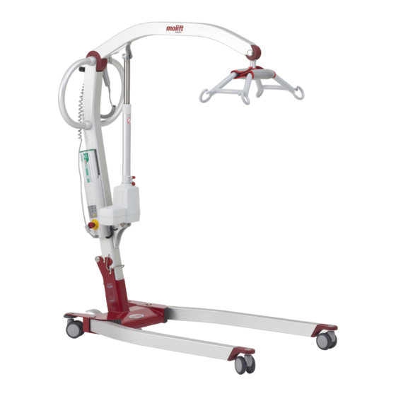
- Page 1 - a patient lifter from TM09201 Molift Smart 150 English...
-
Page 2: Table Of Contents
............14 Hadelandsveien 2 Main components .......... 15 2816 Gjøvik, Norway Teleph: (+47) 40001004 www.molift.com Appendix B ............16 Fax: (+47) 40001008 molift@etac.com Column and lifting arm ........17 Page 2 of 24 TM09201 Molift Smart 150 English - Rev. D1/ 03/2012... -
Page 3: General Advice
General advice Responsibility Please read these operating instructions carefully This technical manual contains important safety before putting the product into operation. We as- instructions and information regarding the service sume no liability for damage or malfunctions re- and repair of the lifter. Carefully read the manual in sulting from failure to comply with the instruc- order to be familiar with function and use, service tions. -
Page 4: Technical Description
The Molift Powerpac system is a custom battery for actuator B and the push/pull handle B pack built up by a 14,4 V battery pack, a charger frame and the charger with wire. Page 4 of 24 TM09201 Molift Smart 150 English - Rev. D1/ 03/2012... -
Page 5: Service
Service Equipment and special tools Equipment Molift Smart 150 has a LED on the battery holder indicating if the lifter needs service. The LED gives The accessories and equipment related to the dai- a green light when the lifter is ready for use. -
Page 6: Fault Finding
• Push out both bolts B , if necessary; tap care- fully using a bolt with the same diameter. • Lift the actuator out and put it carefully down. • Get the new actuator and place it in position - make sure it is placed correctly with the motor Page 6 of 24 TM09201 Molift Smart 150 English - Rev. D1/ 03/2012... -
Page 7: Rear Castors
Front castors housing on the same side as the battery holder. • Push the bolts in place. The castors on the front legs are mounted in brack- • Add Loctite 243 on the threads of the special ets made of plastic cast moulded brackets. If it is the castor C1 screws and tighten them. itself that has been damaged, it is • Connect the cable for the actuator to the cable possible to pull it of and replace it with a new one. -
Page 8: Electronics (Pcb)
• Push the extenders on the emergency lowering switch, and the complete battery supports to- gether. Make sure the PCB enters the slots. • Assemble the holder and screws D Page 8 of 24 TM09201 Molift Smart 150 English - Rev. D1/ 03/2012... -
Page 9: Leg Mechanism / Pedals
• Carefully remove and scrape away any remains Transport elastic of the old sticker before placing the new one. • Connect the cables on backside of battery sup- You will need: port to cables on lifter and place them in slot. • New elastic • Attach the battery support to the column with • Knife or scissors the two screws B , use Loctite 243 on screws. Procedure: Make sure the cables do not get squeezed. -
Page 10: Suspension / O-Ring In Suspension
Designed/Drawn: Date: Projection: Scale: Drawing name: Page 10 of 24 TM09201 Molift Smart 150 English - Rev. D1/ 03/2012 ... -
Page 11: Lifting Column Stopper
Lifting column stopper Plugs in column lock You will need: You will need: • Special pop rivets 4x8,5 mm and tool • Drill steel 3mm and 6,1 mm • Drill steel Ø 5mm • New nylon plugs C 17.2 • New parts Procedure: • Drill a 3 mm pilot hole in the remaining nylon. Procedure: • Remove the lifting column from the chassis. • Carefully drill out the pop rivets C at the back Be careful when drilling out the nylon. Do not of the chassis damage the lock itself. -
Page 12: Finishing The Job
Please make copies of this and next page! Serial number of lifter:___________________________ Date Description of fault Repair Date/sign. Page 12 of 24 TM09201 Molift Smart 150 English - Rev. D1/ 03/2012... -
Page 13: Inspection Diagram After Service And Repair
Service is completed : - Replaced lifting motor/actuator. Worn or damaged parts, or malfunctioning parts, are re- placed. See description for parts replacement. Service light was reset using Molift Servicetool. N.B.: The service light must ONLY be reset after completed service! Perform safety inspection after service. - Page 14 Battery NiMH 2,2 Ah 14,4 V 1340100 Charger NiMH/NiCd 0920057 Appendix D Battery support w electronics 0920084 Appendix E Suspension complete 0920084 Appendix F Electrical diagram Molift Smart 150 Page 14 of 24 TM09201 Molift Smart 150 English - Rev. D1/ 03/2012...
-
Page 15: Main Components
Main components Page 15 of 24... - Page 16 Screw M6x20 DIN912 8.8 Elzn 0920119 Stretch relief 6,4 mm 0540508 Screw 4,5x13 DIN7981C Elzn 0920010 Label Molift Smart 0920084 El. diagram Smart 150 (see app. F) 0910150 Padding suspension Smart Page 16 of 24 TM09201 Molift Smart 150 English - Rev. D1/ 03/2012...
-
Page 17: Column And Lifting Arm
Column and lifting arm Locktite 2701. Locktite 243. Locktite 243. ... - Page 18 0920223 Extension spring SF-DF 1x8x18 0920209 Screw DIN912 M8x65 Elzn 1150414 Nut, lock DIN985 M8 Elzn 0228125 Nut, lock DIN985 M6 Elzn 0920306 Label Molift Smart 150 Page 18 of 24 TM09201 Molift Smart 150 English - Rev. D1/ 03/2012...
-
Page 19: Chassis / Leg Mechanism
Designed/Drawn: Date: Projection: Scale: 30/09-2008 Drawing name: Eccentric Lock Mounted Complete bottom Chassis Drawing number: Size 03-252 Released For Production 30.09.2008/TES Molift Smart Rev. Description: Date/Sign. Approved: Loctite 243. Loctite 243. Loctite 2701. Assembly instructions Chassis= 03-P05 Bill of materials: 03-284 BOM.xls... - Page 20 Mec extender 7mm 2S07 Smart 0421142 Cable clip male 6,3x0,8x1,5 Insulated 0421143 Cable clip female 6,3x0,8x1,5 Insulated 0920092 Battery cable (+) red Smart 0920093 Battery cable (-) black Smart Page 20 of 24 TM09201 Molift Smart 150 English - Rev. D1/ 03/2012...
-
Page 21: Battery Holder / Electronics
Battery holder / electronics Pos. Qty. ... -
Page 22: Electrical Diagram
Hand control Column Designed/Drawn: Date: Projection: Scale: 12.08.2009 Drawing name: Electrical diagram 03-2 Molift SMART 150 Drawing number: Uppdate, new drawing 11.11.2009 TÅB Rev. Description: Date/Sign. Approved: Page 22 of 24 TM09201 Molift Smart 150 English - Rev. D1/ 03/2012... - Page 23 Page 23 of 24...
- Page 24 Strohbogasse 8 Mediscan Systems Ltd 1210 Wien United Kingdom P.B Box 2195 Tel. 01-405 35 43 Meditec Molift Ltd 6 Hamanov St. Fax 01-406 81 02 Rehovot 76386 Hi Trac House www.bstaendig.at IL-76121 Rehovot Unit 1 Woodrow Business Centre Belgium www.mediscan.co.il...
Need help?
Do you have a question about the smart 150 and is the answer not in the manual?
Questions and answers
How long will the battery last on (1) charge, and is this a Lithium type battery, and are replacements batteries readily available, also no spec or callout what is required for a charger
The Molift Smart 150 battery lasts for approximately 40 lifts per full charge (based on 75 kg/165 lb, 50 cm up/down). It is a 14.4V NiMH (Nickel-Metal Hydride) battery, not a Lithium battery. The availability of replacement batteries is not specified. The required charger is the Mascot type 2215, compatible with 10-22 cells NiCd/NiMH batteries.
This answer is automatically generated
Changing wheels on molift 150