Table of Contents
Advertisement
Quick Links
Advertisement
Table of Contents

Related Manuals for Silent Witness SWC40 Series


Summary of Contents for Silent Witness SWC40 Series
- Page 1 SWC40 Series Surveillance Camera User Guide DOCUMENT 920.0083 REV 1.00...
- Page 2 Notices - Warnings Please read the instructions in this guide carefully before you start installing the SWC40 Series Surveillance Camera. Keep this guide for future reference. Safety Warning Any connection of this device to any equipment other than the intended application may result in a safety hazard, and/or defective operation, and/or equipment damage.
-
Page 3: Table Of Contents
Table of Contents Table of Contents..........1 Features ..............2 Unpacking.............. 4 Installation ............. 5 Mounting the Camera ..........5 Wiring the Camera............8 Aiming the Camera ..........10 Adjusting Audio Sensitivity ........12 Recording ............14 Recording Modes............14 Using the Handheld Remote Control.......16 Using the Camera Buttons........17 Playback .............. -
Page 4: Features
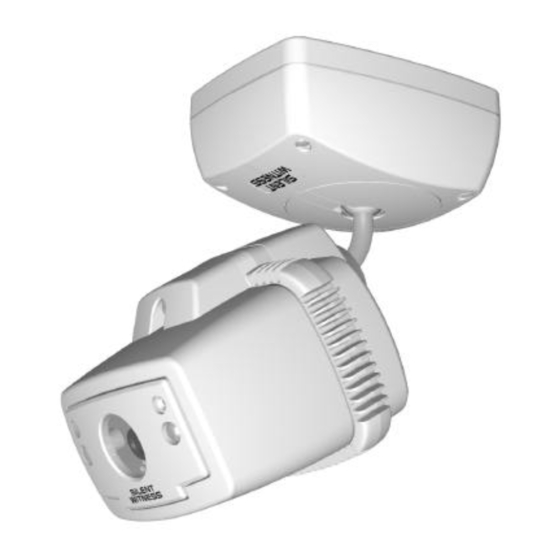
Thank you for purchasing the SWC40 Series Surveillance Camera - the first all-in-one CCTV solution. The SWC40 Series is a high performance camera with digital video recording and video motion detection all within a single compact enclosure that is elegant yet weather resistant and vandal proof. - Page 5 Features - continued Ceiling mount Mounting base Universal mount Camera enclosure Microphone Remote control...
-
Page 6: Unpacking
User Guide you are now reading: One Product Warranty Card One Quick Setup Guide One SWC40 Series Camera (enclosure and mounting base with factory installed audio/video/power cable) Two remote control units Two power adapters One Quick Change Lens Pack with 2.9, 6.9 and 8.0... -
Page 7: Installation
Installation Mounting the Camera The SWC40 Series Camera is designed to be mounted on a wall or ceiling. The SWC40 is weather sealed for indoor or outdoor locations. The wiring can be surface mounted or completely concealed to reduce the risk of tampering. - Page 8 Installation - continued Use the security hex key to remove the four #6-32×1¼" machine screws securing the cover to the mounting base. Position the connector block as shown below and remove the cover. If you do not intend to use the external arming or triggering inputs or the alarm output signals, skip this step.
- Page 9 Installation - continued Use the four #10×1" Phillips self-tapping screws and neoprene washers (included in the SWC40 Installation Kit) to attach the SWC40 mounting base to the wall or ceiling. Alternate fasteners can be used provided they are not Note: larger in diameter than a #10 screw and provided that neoprene washers are used to properly seal the SWC40 mounting base.
-
Page 10: Wiring The Camera
Installation - continued Wiring the Camera For secure installations, surface mounted cables should Note: be protected by plastic or metal cable covers (raceways) such as those manufactured by Wiremold or Panduit. The SWC40 is supplied with a factory installed audio/video/power cable. An external signal cable is provided for installations that use the external arming, triggering, or alarm signals (see Mounting the Camera on page 5 for external signal cable installation... - Page 11 For longer cable runs, use 75Ω coaxial cable and BNC connectors to extend the video signal. Use paired, shielded wire to extend the power, audio, and external input/output signals. The best type of cable to use will depend on the installation. Contact your Silent Witness dealer for more information.
-
Page 12: Aiming The Camera
Installation - continued Aiming the Camera υ To aim the camera Rotate the pivot arm base plate so the slot is directed toward the camera view. Be careful not to turn the base plate so far that it damages the internal wiring. Install the mounting base cover. - Page 13 Installation - continued Use the security hex key to loosen (but not remove) the three machine screws that lock the pivot arm ball joint in the connector block. Plug the camera enclosure onto the connector block and secure it in place with the #6-32×2" retaining screw.
-
Page 14: Adjusting Audio Sensitivity
The audio output signal is always available at the audio output connector of the audio/video/power cable. The audio signal is not recorded by the SWC40. The audio sensitivity of SWC40 Series Cameras may need to be increased in quiet locations or decreased in noisy locations. - Page 15 Installation - continued Camera enclosure Audio sensitivity trimmer Microphone Video connector EXIT button Front panel...
-
Page 16: Recording
Recording The SWC40 has a built in, programmable, digital video recorder that can be triggered by an internal video motion detector and/or by an external trigger signal. The image quality, recording rate, recording duration, and trigger source can be programmed from on-screen menus (see the Programming section of this guide on page 22 for details). - Page 17 Recording - continued While the SWC40 is disarmed, arming, armed, or recording, a live video signal is output with a user programmable time, date, and title overlay. Turning power off while the SWC40 is arming, armed, or recording will arm the SWC40 when power is restored.
-
Page 18: Using The Handheld Remote Control
Recording - continued Using the Handheld Remote Control The SWC40 can be armed or disarmed using a handheld remote control that fits on a key ring. The radio signal range of the remote control is at least 20 feet (6 meters) if there are no walls or obstructions blocking the signal. -
Page 19: Using The Camera Buttons
Recording - continued Using the Camera Buttons The SWC40 can also be armed or disarmed using buttons on the front or back of the camera enclosure. Front Back ω ω υ υ ω ω υ υ FORWARD FORWARD τ τ ϖ ϖ τ... - Page 20 Recording - continued This page intentionally left blank.
-
Page 21: Playback
Playback In playback mode, the SWC40 Surveillance Camera displays previously recorded images. The images can be viewed in forward or reverse order, at normal speed, fast speed or one image at a time. Playback Setup Recorded video images can be played back while the SWC40 is attached to the mounting base or the SWC40 can be detached from the mounting base for more convenient access to the playback controls on the back... -
Page 22: Playback Recorded Images
Playback - continued υ To playback while the SWC40 is attached to the mounting base. Use the security hex key provided in the SWC40 Installation Kit to remove the two machine screws that secure the front panel of the camera enclosure. Remove the front panel. - Page 23 Playback - continued υ To enter playback mode While the SWC40 is disarmed, press either the ω ω υ υ τ τ ϖ ϖ buttons (but not both at the FORWARD REVERSE ω ω υ υ same time) to go to playback mode. will FORWARD display the first image recorded in the most recent...
-
Page 24: Programming
Programming Many features and operational parameters of the SWC40 Surveillance Camera are user programmable from on-screen menus. The SWC40 can be programmed while it is attached to the mounting base or it can be detached from the mounting base for more convenient access to the controls on the rear of the camera enclosure. - Page 25 Programming - continued υ To program the SWC40 while it is attached to the mounting base Use the security hex key provided in the SWC40 Installation Kit to remove the two machine screws that secure the front panel of the camera enclosure. Remove the front panel of the camera enclosure.
- Page 26 While in program mode, if no buttons are pressed for 30 seconds, the SWC40 will automatically return to disarmed mode. When you first go to program mode, the following text display will overlay the live video signal. ©1999 Silent Witness Enterprises Ltd. Experience Innovation Support: 1-800-893-9513 Or Call: 1-604-574-1523 SWC40 Version 01.00P...
- Page 27 Programming - continued While the SWC40 is in program mode, the four buttons on the front and back of the camera enclosure function as follows: τ τ ϖ ϖ If you are selecting a menu item, press this button to REVERSE move the menu cursor up one item in a menu list.
-
Page 28: Record Menu
Programming - continued Record Menu ω ω υ υ τ τ ϖ ϖ On the Main Menu, use the FORWARD REVERSE buttons to position the menu cursor at Record. Press the button to display the Record menu. DISPLAY Record Menu ®... - Page 29 Programming - continued This option sets the time between recorded images. The Rate range of values is: 0.5 seconds/image (2 images per second) 1 second/image (1 image per second, default value) 2 seconds/image (1 image every 2 seconds) 5 seconds/image (1 image every 5 seconds) The SWC40 can record images at three quality levels: Quality Good...
-
Page 30: Intelligent Light Compensation (Ilc) Menu
Programming - continued Intelligent Light Compensation (ILC) Menu The Intelligent Light Compensation (ILC) feature automatically adjusts the electronic shutter speed and other operating parameters of the camera based on light levels in specific areas of interest in the image. This compensation provides better image quality for scenes that are unevenly lit. - Page 31 Programming - continued This option allows you to specify which areas of the Tile Setup image will be used to adjust camera lighting compensation. When you select this menu item, a tiled grid will overlay the live video image. ω ω υ υ τ...
-
Page 32: Motion Menu
Programming - continued Motion Menu The SWC40 has a built in video motion detector. The Motion menu allows you to adjust video motion detection parameters. ω ω υ υ τ τ ϖ ϖ On the Main menu, use the FORWARD REVERSE buttons to position the menu cursor at Motion. - Page 33 Programming - continued Sensitivity This option sets the sensitivity of the motion detector. When this option is selected, the letters L (low) and H (high) on the sensitivity scale will flash. Use the ω ω υ υ τ τ ϖ ϖ buttons to increase or FORWARD REVERSE...
-
Page 34: Display Menu
DISPLAY Display Menu ® Time 12:35:47 Date Feb 17 1999 Title Silent Witness Position Bottom-Right Visible Time This option allows you to set the time of day. The time is shown as Hours:Minutes:Seconds and a or p for AM and PM. The Seconds field is not adjustable - it is automatically set to zero when the other time fields are changed. - Page 35 Programming - continued This option allows you to set the calendar date. The date Date is shown as Month Day Year. The first two digits of the year can be set to . The last two digits of the 19, 20 year can be set to any number from Press the button to cycle through the Month,...
-
Page 36: Alarm Menu
Programming - continued Alarm Menu The Alarm menu allows you to set parameters that control the external alarm output signal. ω ω υ υ τ τ ϖ ϖ On the Main menu, use the FORWARD REVERSE buttons to position the menu cursor at Alarm. Press the button to see the Alarm menu. - Page 37 Programming - continued This option specifies the type of alarm output signal. Output Pulse The alarm output is activated for 1 second each time it is triggered. Latched The alarm output remains activated until the camera is disarmed. This option allows the alarm output signal to be delayed. Output Delay Instant The alarm output is activated immediately when an alarm event occurs.
-
Page 38: Input Menu
Programming - continued Input Menu The Input menu allows you to set parameters that determine how the external arming and trigger signals control the operation of the camera. ω ω υ υ τ τ ϖ ϖ On the Main menu, use the FORWARD REVERSE buttons to position the menu cursor at Input. - Page 39 Programming - continued This option specifies the arming delay after the external Arm Delay arming signal transition. Instant Arms the camera immediately when an external arming signal occurs. 30 Seconds Arms the camera 30 seconds after an external arming signal occurs. This option specifies the external trigger signal transition Ext.
-
Page 40: Learning A New Remote Control Code
Programming - continued Learning a New Remote Control Code Each SWC40 remote control unit has a unique digital identification code. If you lose a remote control unit or require additional units, contact your SWC40 distributor or salesperson to order an SWC40 Remote Control Kit. Before you can use a new remote control unit, your camera must learn the digital identification code of the new unit. -
Page 41: Routine Maintenance
Routine Maintenance Regular liquid cleaners or graffiti gel can be used to remove most substances from the SWC40 enclosure. Do not use alcohol or solvents to clean the camera Caution: enclosure, window, or mounting base. Although the Lexan window in the SWC40 camera Caution: enclosure is scratch resistant, harsh or abrasive cleaners can scratch the window and reduce visibility of the... -
Page 42: Troubleshooting
Troubleshooting υ Front panel light is off See page 15 for a description of the front panel indicator light patterns. Make sure the camera is not in playback or programming modes. Make sure the power adapter is powered and connected to the camera. If you are not using the original power adapter, make sure the power supply voltage is between 8.5 and 18 Vdc (positive voltage on center pin). - Page 43 Troubleshooting - continued υ Camera cannot be armed or disarmed by remote control Make sure the front panel light is not off (see related troubleshooting item above). Make sure you are less than 20 feet (6 meters) from the camera with no obstructions. Make sure the light on the remote control turns on when the button is pressed.
- Page 44 Make sure the External Trigger option on the Input programming menu is not Off. Check the external trigger signal voltage level and polarity. Call the Silent Witness Service Department for additional assistance (see the Warranty and Service section of this guide on page 43 for telephone numbers).
-
Page 45: Warranty And Service
Warranty and Service Subject to the terms and conditions listed on the Product Warranty Card, during the warranty period, Silent Witness will repair or replace, at its sole option, free of charge any defective products returned by prepaid shipping. In the event you have a problem with any Silent... -
Page 46: Regulatory Notices
Regulatory Notices FCC Statement (U.S.A.) This device complies with Part 15 of the FCC Rules. Operation is subject to the following conditions: (1) This device may not cause harmful interference, and (2) this device must accept any interference received, including interference that may cause undesired operation Industry Canada Notice This Class B digital apparatus meets all requirements of... -
Page 47: Specifications
Specifications Power Requirements Input voltage: 8.5 to 18 Vdc Power connector polarity: Positive voltage on center pin Power consumption: 500 mA at 12 Vdc Size and Weight Dimensions: (W × H × D) 4.5" × 4" × 5" (excluding base) 114 mm ×... - Page 48 Specifications - continued Recording Sequence Storage Capacity Maximum Number of Sequences Stored at GOOD Image Quality Recording Rate (seconds/image) Recording Time 1 image 1140 1140 1140 1140 2 seconds 1140 5 seconds 10 seconds 1 minute 5 minutes Full Maximum Number of Sequences Stored at HIGH Image Quality Recording Rate (seconds/image) Recording Time 1 image...
-
Page 49: Mounting Template
Mounting Template 1.90" 48 mm Cable access hole 0.25" 6 mm 3.46" 88 mm Wall mount this way up 2.99" 76 mm... - Page 50 This page intentionally left blank.
- Page 52 www.silent-witness.com Sales: (888) 289-2288 6554 – 176 Street Service: (800) 893-9513 Surrey, BC V3S 4G5 Phone: (604) 574-1526 CANADA Fax: (604) 574-1527...
Need help?
Do you have a question about the SWC40 Series and is the answer not in the manual?
Questions and answers