Table of Contents
Advertisement
Quick Links
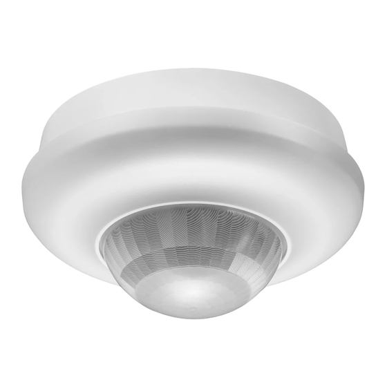
Presence and motion detector DALI-2 BMS
41-742, 41-743 and 41-745
Valid for software version 2 -
Use
DALI-2 BMS detector 360° is used to detect presence and to measure the
actual light level. The detector is connected directly to a DALI bus.
The detector can be installed in connection with a BMS / CTS system.
This gives an effective and energy-saving solution that is integrated with the
application controller.
The detector is DALI-2 compliant and complies with the relevant DALI
Standards. The detector has its own address range on the DALI bus,
which means that the number of detectors does not affect the number of
luminaires that can be connected to the DALI bus.
Function
The detector is connected to the DALI bus. To achieve complete coverage
when using several detectors, is an overlap of approximately 30 %
recommended.
Fig. 2.
The detector does not contain a full daylight control. It can only provide
information about presence and lux level. The underlying application
controller must be able to handle daylight control.
Installation
Location:
The detector responds to movement and heat in the surroundings. Avoid
positioning the detector close to heat sources such as cookers, electric
radiators or ventilation systems or moving objects such as hanging mobiles,
etc. This may result in unintended activation.
Niko-Servodan A/S
see version no.
Fig. 1.
Stenager 5
DK-6400 Sønderborg
•
•
Type no.
41-742
Flush mounted
Fig. 3.
Fig. 4.
Surface mounted
Installation height 2-3,4 m
Installation height 4-8 m
Installation height - type 41-742 and 41-743:
The recommended installation height for this detector is 2–3.4 m. 2.5 m is
the ideal installation height. At this height, the detector has a range of Ø20 m
on ground level and Ø13.5 m at 80 cm table height (without lens cover).
Fig. 6.
Installation - type 41-745:
The recommended installation height for this detector is 4–8 m. At this
height, the detector has a range of Ø16–32 m on ground level (without lens
cover).
Fig. 7.
Connection:
The detector must be connected to the DALI bus. Once connected, the
detector will be ready to operate after approx. 2 minutes (warm-up time).
Connect the detector according to the connection diagram.
Setting
Factory setting:
Sensitivity:
High sensitivity, all segments
0 - 1023 lux
All settings of sensitivity and lux are made via the application controller.
In addition, an IR remote control type 41-934 (accessory) can be used for
testing, settings of sensitivity and for software version control.
In order to use the IR remote, the detector must be provided via the DALI
bus.
In order to change settings, the detector must be unlocked. The detector
is automatically locked after five minutes if this is not done manually. Any
changes to settings will be saved. When settings have been programmed,
the green LED turns off briefly, acknowledging that information has been
received correctly.
Fig. 9.
Lock/unlock:
Press "Lock / unlock" once to unlock the detector for setting. The green LED
lights up when the detector is in the setting mode.
Press "Lock / unlock" again to lock the detector - operating mode. The green
LED turns off.
tel +45 7442 4726
info@niko.dk
•
•
User manual / EN
41-743
41-745
•
•
•
•
•
•
Fig. 8.
Table 1.
Fig. 10-14.
www.niko.dk
•
1(7)
Advertisement
Table of Contents

Subscribe to Our Youtube Channel
Related Manuals for Niko DALI-2 BMS 41-742


Summary of Contents for Niko DALI-2 BMS 41-742
- Page 1 Press "Lock / unlock" once to unlock the detector for setting. The green LED lights up when the detector is in the setting mode. Press "Lock / unlock" again to lock the detector - operating mode. The green LED turns off. Niko-Servodan A/S Stenager 5 DK-6400 Sønderborg tel +45 7442 4726 info@niko.dk...
- Page 2 Installation height ........4 – 8 m Certifications: CE in accordance with......EN 60669-2-1 Standards: DALI ............IEC 62386-101 IEC 62386-103 IEC 62386-303 IEC 62386-304 Niko-Servodan A/S Stenager 5 DK-6400 Sønderborg tel +45 7442 4726 info@niko.dk www.niko.dk 2(7) • •...
- Page 3 30 % Fig. 3 - type no. 41-742 Fig. 4 - type no. 41-743 and 41-745 117,3 88,5 Gasket for IP 54 Lens cover Lens cover Niko-Servodan A/S Stenager 5 DK-6400 Sønderborg tel +45 7442 4726 info@niko.dk www.niko.dk 3(7) •...
- Page 4 Burn in Status Burn in Status zone zone On/O Auto Dim - Dim + On/O Auto Dim - Dim + Niko-Servodan A/S Stenager 5 DK-6400 Sønderborg tel +45 7442 4726 info@niko.dk www.niko.dk 4(7) • • • • • Min./ Min./ 8 hour Sens.
- Page 5 60 min 45 min 60 min Min./ 8 hour Sens. Calib. Fact. Fact. Time Mode Time Mode set. set. Niko-Servodan A/S Stenager 5 DK-6400 Sønderborg tel +45 7442 4726 info@niko.dk www.niko.dk 5(7) • • • • • Burn in Status zone...
- Page 6 Sens. Calib. On/O Auto Dim - Dim + 4 = Minimum 0.5 s On/O Auto Dim - Dim + 5 = Off Niko-Servodan A/S Stenager 5 DK-6400 Sønderborg tel +45 7442 4726 info@niko.dk www.niko.dk 6(7) • • • • •...
- Page 7 0 = MAX, 1 = HIGH, 2 = LOW, 3 = MIN, 4 = OFF 0x06 LUX range 0x00 0 = NORMAL 0-1.023 Lux, 10-bit 1 = HIGH 0-10.360 Lux, 14-bit Niko-Servodan A/S Stenager 5 DK-6400 Sønderborg tel +45 7442 4726 info@niko.dk www.niko.dk 7(7) •...
Need help?
Do you have a question about the DALI-2 BMS 41-742 and is the answer not in the manual?
Questions and answers