
Related Manuals for National Instruments PXI-8195


Summary of Contents for National Instruments PXI-8195
- Page 1 NI PXI-8195/8196 User Manual NI PXI-8195/8196 User Manual March 2005 371445A-01...
- Page 2 For further support information, refer to the Technical Support and Professional Services appendix. To comment on National Instruments documentation, refer to the National Instruments Web site at ni.com/info and enter the info code feedback. © 2005 National Instruments Corporation. All rights reserved.
- Page 3 The reader should consult National Instruments if errors are suspected. In no event shall National Instruments be liable for any damages arising out of or related to this document or the information contained in it.
- Page 4 These classes are known as Class A (for use in industrial-commercial locations only) or Class B (for use in residential or commercial locations). All National Instruments (NI) products are FCC Class A products. Depending on where it is operated, this Class A product could be subject to restrictions in the FCC rules. (In Canada, the Department of Communications (DOC), of Industry Canada, regulates wireless interference in much the same way.) Digital...
-
Page 5: Table Of Contents
Description ......................1-1 Functional Overview ..................1-2 National Instruments Software ..................1-4 Chapter 2 Installation and Configuration Installing the NI PXI-8195/8196 ...................2-1 How to Remove the Controller from the PXI Chassis ........2-4 BIOS Setup ........................2-4 Entering BIOS Setup ..................2-4 Main Setup Menu ....................2-5 Advanced Setup Menu ..................2-6... - Page 6 Software Driver Installation ..................4-3 Chassis Configuration ....................4-4 Basic PXI System Configuration ..............4-5 Upgrade Information ..................... 4-6 PXI Configuration ......................4-8 Chapter 5 Troubleshooting Appendix A Specifications Appendix B Technical Support and Professional Services Glossary Index NI PXI-8195/8196 User Manual ni.com...
-
Page 7: About This Manual
This manual contains detailed instructions for installing and configuring your National Instruments NI PXI-8195/8196 embedded computer kit. How to Use the Documentation Set Begin by reading the NI PXI-8195/8196 Installation Guide, a brief quick-start guide that describes how to install and get started with your controller. -
Page 8: Related Documentation
PXI Hardware Specification, Revision 2.1, PXI Systems Alliance • PXI Software Specification, Revision 2.1, PXI Systems Alliance • Serialized IRQ Support for PCI Systems Specification, Revision 6.0, Compaq Computer et al. • ExpressCard Standard, Release 1.0, PCMCIA NI PXI-8195/8196 User Manual viii ni.com... -
Page 9: Introduction
Description The NI PXI-8195/8196 PXI/CompactPCI embedded computer is a high-performance PXI/CompactPCI-compatible system controller. The NI PXI-8195/8196 controller integrates standard I/O features in a single unit by using state-of-the-art packaging. Combining an NI PXI-8195/8196 embedded controller with a PXI-compatible chassis, such as the PXI-1042, results in a fully PC-compatible computer in a compact, rugged package. -
Page 10: Functional Overview
USB 2.0 ports, Gigabit ENET, a reset button, and a PXI trigger. The NI PXI-8195 has a 1.5 GHz processor, all the standard I/O, and a 30 GB (or larger) hard drive. The NI PXI-8196 has a 2.0 GHz processor, all the standard I/O, and a 30 GB (or larger) hard drive. - Page 11 Super I/O Watchdog COM 1 Figure 1-1. NI PXI-8195/8196 Block Diagram The NI PXI-8195/8196 consists of the following logic blocks on the CPU module and the I/O (daughter card) module. The CPU module has the following logic blocks: • Socket 479 CPU is the socket definition for the Intel Pentium M processor families.
-
Page 12: National Instruments Software
The PXI Connector connects the NI PXI-8195/8196 to the PXI/CompactPCI backplane. • The Super I/O block represents the other peripherals supplied by the NI PXI-8195/8196. The NI PXI-8195/8196 has one serial port, and an ECP/EPP parallel port. • The IDE block is dedicated PCI-IDE circuitry providing fast ATA-100 transfers to the internal 2.5 in. - Page 13 Chapter 1 Introduction You also can use the National Instruments LabVIEW, Measurement Studio, ™ ™ and LabWindows /CVI application programs and instrument drivers to ease your programming task. These standardized programs match the modular virtual instrument capability of PXI and can reduce your PXI software development time.
-
Page 14: Installation And Configuration
NI PXI-8195/8196 controller. Installing the NI PXI-8195/8196 This section contains general installation instructions for the NI PXI-8195/8196. Consult your PXI chassis user manual for specific instructions and warnings. Plug in your chassis before installing the NI PXI-8195/8196. The power cord grounds the chassis and protects it from electrical damage while you install the module. - Page 15 Figure 2-1. Removing Protective Screw Caps Make sure the injector/ejector handle is in its downward position. Align the NI PXI-8195/8196 with the card guides on the top and bottom of the system controller slot. Do not raise the injector/ejector handle as you insert the NI PXI-8195/8196.
- Page 16 What if the NI PXI-8195/8196 does not boot? section of Chapter 5, Troubleshooting. Figure 2-2 shows an NI PXI-8196 installed in the system controller slot of a National Instruments PXI-1042 chassis. You can place PXI devices in any other slot. 1 PXI-1042 Chassis 2 NI PXI-8196 Controller 3 Injector/Ejector Rail Figure 2-2.
-
Page 17: How To Remove The Controller From The Pxi Chassis
Chapter 2 Installation and Configuration How to Remove the Controller from the PXI Chassis The NI PXI-8195/8196 controller is designed for easy handling. To remove the unit from the PXI chassis, complete the following steps: Power off the chassis. Remove the bracket-retaining screws in the front panel. -
Page 18: Main Setup Menu
However, if an IDE/ATA device is not autodetected properly, you can specify it manually by pressing <Enter> on an item. • System Information—This setting displays a screen containing important system information about the NI PXI-8195/8196 controller. © National Instruments Corporation NI PXI-8195/8196 User Manual... -
Page 19: Advanced Setup Menu
Yes to force the BIOS to recreate the ESCD on the next reboot. This is rarely necessary. • Integrated Peripherals—Use this setting to bring up the Integrated Peripherals submenu. (Refer to the Integrated Peripherals Submenu section.) NI PXI-8195/8196 User Manual ni.com... - Page 20 Integrated Peripherals Submenu Use this submenu to apply nondefault configurations to the front panel peripherals of an NI PXI-8195/8196 controller. Normally, you do not need to modify these settings, as the factory default settings provide the most compatible and optimal configuration possible.
-
Page 21: Pxi Setup Menu
Per-Slot Device Settings Submenu Use this menu to configure options that can be modified for individual PCI devices in a PXI chassis. Note Scanning for Option ROMs on devices behind a PCI bridge cannot be disabled. NI PXI-8195/8196 User Manual ni.com... -
Page 22: Labview Rt Options Setup Menu
IDE 0—The internal IDE hard drive, connected to IDE Channel 0 master. • USB HDD—A USB based flash drive or hard disk drive. • USB CDROM—A USB based CD-ROM drive. • USB FDC—A USB based floppy disk drive. © National Instruments Corporation NI PXI-8195/8196 User Manual... -
Page 23: Exiting Bios Setup
Discarding Changes, however, the BIOS setup continues to be active. • Save Changes—Changes made to BIOS settings during this session are committed to battery-backed System CMOS. The setup program remains active, allowing further changes. NI PXI-8195/8196 User Manual 2-10 ni.com... -
Page 24: System Cmos
Chapter 2 Installation and Configuration System CMOS The NI PXI-8195/8196 contains a backed-up memory used to store BIOS configuration information. Complete the following steps to clear the CMOS contents: Power off the chassis. Remove the controller from the chassis. Move the jumper on W1 from pins 1–2 to pins 2–3, as shown in Figure 2-3. -
Page 25: Labview Rt Configuration Switches
OFF position. The controller reads these switches only after a system reset. You must reboot the controller for any changes to take place. The NI PXI-8195/8196 controller includes the following LabVIEW RT configuration switches: •... - Page 26 The switches are shown in the OFF position. 1 Switch 1—Boot LabVIEW RT 3 Switch 3—Disable Startup VI 2 Switch 2—Boot Safe Mode 4 Switch 4—Reset IP Address Figure 2-4. LabVIEW RT Configuration Switches © National Instruments Corporation 2-13 NI PXI-8195/8196 User Manual...
-
Page 27: Drivers And Software
PXI Features PXI Trigger Connectivity The SMB connector on the NI PXI-8195/8196 front panel can connect to or from any PXI backplane trigger line through software. A trigger allocation process is needed to prevent two resources from connecting to the same trigger line, resulting in the trigger being double-driven and possibly damaging the hardware. -
Page 28: Upgrading Ram
Chapter 2 Installation and Configuration Upgrading RAM You can change the amount of installed RAM on the NI PXI-8195/8196 by upgrading the SO-DIMM. To upgrade the RAM, remove the NI PXI-8195/8196 from the PXI chassis. To optimize both memory capacity and system performance, use the same size and speed memory module in each of the two module slots. -
Page 29: Hard Drive Recovery
Installation and Configuration 1 DDR2 SO-DIMM Module 2 DDR2 SO-DIMM Socket Figure 2-5. Installing a DDR2 SO-DIMM in an NI PXI-8195/8196 Controller Hard Drive Recovery NI PXI-8195/8196 controllers include Phoenix Technologies Ltd. Firstware tools, either Recover or Vault, or both. These tools allow you to recover the original factory condition of the hard disk from a small protected area of your hard drive. -
Page 30: Installing An Os
OS. When doing so, consider the following guidelines. Installing from a CD-ROM The NI PXI-8195/8196 supports the installation of Windows XP from a USB CD-ROM. However, many other operating systems do not support installation from a USB CD-ROM. For example, Windows 2000 aborts during the install process because it does not have drivers for the CD-ROM device. -
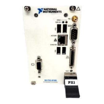
Page 31: Front Panel Connectors
I/O Information Front Panel Connectors Table 3-1 lists various peripherals and their corresponding NI PXI-8195/8196 external connectors, bus interfaces, and functions. Table 3-1. NI PXI-8195/8196 Peripherals Overview External PXI- 8195/8196 Peripheral Connector Description Models Video Intel Extreme Graphics (15-pin DSUB) -
Page 32: Front Panel
Front Panel Figure 3-1 shows the front panel layout and dimensions of the NI PXI-8196, and Figure 3-2 shows the front panel layout and dimensions of the NI PXI-8195. Dimensions are in inches [millimeters]. 4.39 [111.5] 3.84 [97.5] 3.55 [90.2] 3.29 [83.6]... -
Page 33: Vga
Figure 3-2. NI PXI-8195 Front Panel Layout and Dimensions Figure 3-3 shows the location and pinouts for the VGA connector on the NI PXI-8195/8196. Table 3-2 lists and describes the VGA connector signals. AMP manufactures a mating connector with part numbers 748364-1 (housing) and 748333-2 (pin contact). - Page 34 Figure 3-3. VGA Connector Location and Pinout Table 3-2. VGA Connector Signals Signal Name Signal Description Green Blue Not Connected Ground Ground Ground Ground Ground Not Connected Serial Data HSync Horizontal Sync VSync Vertical Sync Serial Clock NI PXI-8195/8196 User Manual ni.com...
-
Page 35: Com1
Chapter 3 I/O Information COM1 Figure 3-4 shows the location and pinouts for the COM1 connector on the NI PXI-8195/8196. Table 3-3 lists and describes the COM1 connector signal. AMP manufactures a serial port mating connector, part number 745491-5. COM1 Figure 3-4. -
Page 36: Ethernet
Chapter 3 I/O Information Ethernet Figure 3-5 shows the location and pinouts for the Ethernet connector on the NI PXI-8195/8196. Table 3-4 lists and describes the Ethernet connector signals. AMP manufactures a mating connector, part number 554739-1. Ethernet Figure 3-5. Ethernet Connector Location and Pinout Table 3-4. -
Page 37: Parallel Port
1000 Mbit/sec data rate is selected. Parallel Port Figure 3-6 shows the location and pinouts for the IEEE 1284 (parallel) connector on the NI PXI-8195/8196. Table 3-6 lists and describes the IEEE 1284 connector signals. Parallel port adapter cables are available from National Instruments, part number 777169-01. - Page 38 Data Bit 2 Data Bit 3 Data Bit 4 Data Bit 5 Data Bit 6 Data Bit 7 INIT* Initialize Printer STROBE* Strobe SLCTIN* Select Input AUTOFD* Auto Line Feed +5 V 19–35 Ground Not Connected NI PXI-8195/8196 User Manual ni.com...
-
Page 39: Universal Serial Bus
I/O Information Universal Serial Bus Figure 3-7 shows the location and pinouts for the Universal Serial Bus (USB) connector on the NI PXI-8195/8196. Table 3-7 lists and describes the USB connector signals. AMP manufactures a USB mating connector, part number 787633. -
Page 40: Trigger
The TRG connector is the software-controlled trigger connection for routing PXI triggers to or from the backplane trigger bus. Figure 3-8 shows the TRG connector location on the NI PXI-8195/8196. Table 3-8 lists and describes the trigger connector signals. Figure 3-8. TRG Connector Location and Pinout Table 3-8. -
Page 41: Gpib (Ieee 488.2)
Data Bit 2 DIO3* Data Bit 3 DIO4* Data Bit 4 EOI* End or Identify DAV* Data Valid NRFD* Not Ready for Data NDAC* Not Data Accepted IFC* Interface Clear SRQ* Service Request © National Instruments Corporation 3-11 NI PXI-8195/8196 User Manual... -
Page 42: Expresscard/34 Slot
Figure 3-10 shows the location and pinouts for the ExpressCard/34 slot on the NI PXI-8196. Table 3-10 lists and describes the ExpressCard connector signals. ExpressCard/34 Slot Figure 3-10. ExpressCard/34 Slot Location and Pinout NI PXI-8195/8196 User Manual 3-12 ni.com... - Page 43 REFCLK– Reference Clock – REFCLK+ Reference Clock + Ground PERn0 PE Data Receive – PERp0 PE Data Receive + Ground PETn0 PE Data Transmit – PETp0 PE Data Transmit + Ground © National Instruments Corporation 3-13 NI PXI-8195/8196 User Manual...
-
Page 44: Front Panel Features
OFF—The power to the controller is off. – The DRIVE LED indicates when an access to the internal hard disk is occurring. Data Storage The NI PXI-8195/8196 has the following data storage features: • Internal IDE hard drive – 2.5 in. notebook hard drive –... -
Page 45: Common Configuration Questions
This chapter answers common configuration questions you may have when using the NI PXI-8186/8187 embedded controller. General Questions What do the LEDs on the NI PXI-8195/8196 front panel mean? Refer to the LED status descriptions in the Front Panel Features... -
Page 46: Cables And Connections
Note can be installed from a USB CD-ROM, but earlier versions of Windows cannot. The NI PXI-8195/8196 BIOS configures the USB devices so that they will work in a DOS environment. How do I configure the controller to boot from these devices? There are two methods. -
Page 47: Software Driver Installation
How do I connect a standard 25-pin LPT cable to the NI PXI-8195/8196? The NI PXI-8195/8186 uses a type C LPT connector. Most parallel port devices use a type A connector. To use a device with a standard type A LPT connector, you need to use a type C-to-type A LPT adapter. -
Page 48: Chassis Configuration
Chapter 4 Common Configuration Questions How do I install software from a CD? The compact size of the NI PXI-8195/8196 does not allow for an integrated CD-ROM drive. If you are using Windows XP, you have the following options: •... -
Page 49: Basic Pxi System Configuration
Identify As submenu. Further expanding the PXI System branch shows all devices in the system that can be recognized by NI-VISA. When your controller and all your chassis are identified, the required file is complete. pxisys.ini © National Instruments Corporation NI PXI-8195/8196 User Manual... -
Page 50: Upgrade Information
Upgrade Information How do I upgrade system memory? You can change the amount of installed RAM on the NI PXI-8195/8196 by upgrading the DDR2 SO-DIMM. To upgrade the RAM, remove the NI PXI-8195/8196 from the PXI chassis. To optimize both memory capacity and system performance, use the same size and speed memory module in each of the two module slots. - Page 51 You can download the latest drivers from ni.com/support/ pxisupp.htm My NI PXI-8195/8196 does not have an internal floppy drive. Is there a way to use an external drive? Yes. The NI PXI-8195/8196 controller supports and can boot from USB floppy drives. A USB floppy drive will not work with Windows NT4, but will work with Windows 2000 or Windows XP.
-
Page 52: Pxi Configuration
Configuration. Why doesn’t the NI PXI-8195/8196 work with the PXI-8220? A serialized IRQ conflict with the PXI-8220 and the NI PXI-8195/8196 prevents PC cards using ISA interrupts from working with the NI PXI-8195/8196 controllers. The PXI-8221 is designed to work with the NI PXI-8195/8196 and should be used instead. -
Page 53: Troubleshooting
This chapter answers common troubleshooting questions you may have when using the NI PXI-8195/8196 embedded computer. What if the NI PXI-8195/8196 does not boot? Several problems can cause a controller not to boot. Here are some things to look for and possible solutions. - Page 54 Select Save and Exit Setup. As an alternative method, complete the following steps: Power off the chassis. Remove the controller from the chassis. Move the jumper on W4 from pins 1–2 to pins 2–3 as shown in Figure 5-1. NI PXI-8195/8196 User Manual ni.com...
- Page 55 Do not leave the jumper on pins 2–3. Doing so decreases battery life. Also, the Caution controller will not boot. 1 Normal Operation (Default) 2 Clear CMOS Contents 3 Pin 1 Figure 5-1. Clearing the CMOS Contents © National Instruments Corporation NI PXI-8195/8196 User Manual...
-
Page 56: Appendix A Specifications
Specifications This appendix lists the electrical, mechanical, and environmental specifications of the NI PXI-8195/8196 embedded computer. Electrical Current (A) Typical Maximum Voltage (V) NI PXI-8195 NI PXI-8196 NI PXI-8195 NI PXI-8196 +3.3 2.8 A 2.8 A 3.2 A 3.2 A 4.8 A... - Page 57 Relative humidity range......10% to 90%, noncondensing (Tested in accordance with IEC-60068-2-56.) Clean the NI PXI-8195/8196 with a soft nonmetallic brush. Make sure that the Caution device is completely dry and free from contaminants before returning it to service. Storage Environment NI PXI-8195/8196 Ambient temperature range .....–20 to 65 °C (Tested in...
- Page 58 FCC Part 15A above 1 GHz Immunity..........EN 61326:1997 + A2:2001, Table 1 EMC ............CE, C-Tick, and FCC Part 15 (Class A) compliant Note For full EMC compliance, operate this device with shielded cabling. © National Instruments Corporation NI PXI-8195/8196 User Manual...
- Page 59 Refer to the Declaration of Conformity (DoC) for this product for any additional regulatory compliance information. To obtain the DoC for this product, visit , search by model number or product line, and click the ni.com/certification appropriate link in the Certification column. NI PXI-8195/8196 User Manual ni.com...
- Page 60 Technical Support and Professional Services Visit the following sections of the National Instruments Web site at for technical support and professional services: ni.com • Support—Online technical support resources at ni.com/support include the following: – Self-Help Resources—For answers and solutions, visit the...
- Page 61 You also can visit the Worldwide Offices section of to access the branch ni.com/niglobal office Web sites, which provide up-to-date contact information, support phone numbers, email addresses, and current events. NI PXI-8195/8196 User Manual ni.com...
- Page 62 Glossary Symbol Prefix Value nano –9 µ micro – 6 –3 milli kilo mega giga tera Symbols ° Degrees. Ω Ohms. Percent. Amperes. Alternating Current. ASIC Application-specific integrated circuit. © National Instruments Corporation NI PXI-8195/8196 User Manual...
- Page 63 Direct Memory Access—A method by which data is transferred between devices and internal memory without intervention of the central processing unit. DRAM Dynamic RAM (Random Access Memory)—Storage that the computer must refresh at frequent intervals. NI PXI-8195/8196 User Manual ni.com...
- Page 64 Hertz—Cycles per second. Input/output—The techniques, media, and devices used to achieve communication between machines and users. Integrated Drive Electronics—Hard disk and built-in controller. IEEE Institute of Electrical and Electronics Engineers. © National Instruments Corporation NI PXI-8195/8196 User Manual...
- Page 65 A functional part of a PXI device that initiates data transfers on the PXI backplane. A transfer can be either a read or a write. Megabytes of memory. MTBF Mean time between failure. MTTR Mean time to repair. NI PXI-8195/8196 User Manual ni.com...
- Page 66 Glossary NI-488 or NI-488.2 The National Instruments software for GPIB systems. NI-DAQ The National Instruments software for data acquisition instruments. NI-VISA The National Instruments implementation of the VISA standard—An interface-independent software that provides a unified programming interface for VXI, GPIB, and serial instruments.
- Page 67 RAM chip, but it does take up more space and uses more power. Universal Serial Bus. Volts. Video Graphics Array—The minimum video display standard for all PCs. Watts. NI PXI-8195/8196 User Manual ni.com...
- Page 68 5-2 installing, 2-15, 4-6 COM1 connector figure, 2-16, 4-7 connector locations and pinout (figure), 3-5 DDR2 SO-DIMMs, from National Instruments connector signals (table), 3-5 (note), 2-15, 4-6 common configuration questions Declaration of Conformity (NI resources), B-1...
- Page 69 (figure), 2-2 connectors, 3-1 instrument drivers (NI resources), B-1 dimensions, 3-2 Integrated Peripherals menu, 2-7 features, 3-14 functional overview of NI PXI-8195/8196, 1-2 keyboard, plugging PS/2 mouse and keyboard into controller, 4-2 KnowledgeBase, B-1 NI PXI-8195/8196 User Manual ni.com...
- Page 70 3-1 os directory, 2-14 COM1 connector and signals, 3-5 OS installation ExpressCard/34 connector and from CD-ROM, 2-17 signals, 3-12 GPIB (IEEE 488.2) connector and signals, 3-11 parallel port connector and signals, 3-7 © National Instruments Corporation NI PXI-8195/8196 User Manual...
- Page 71 PXI Setup menu, 2-8 switches Per-Slot Device Settings, 2-8 LabVIEW RT configuration, 2-12 PXI trigger connectivity, 2-14 figure, 2-13 PXI-8220, using NI PXI-8195/8196 with, 4-8 system CMOS, 2-11 pxisys.ini file, 4-4 system reset pushbutton, 3-14 technical support, B-1 DDR2 SO-DIMMs from National...
- Page 72 4-3 using with PS/2 mouse and keyboard, 2-3 connector signals (table), 3-4 location and pinout (figure), 3-4 overview (table), 3-1 video, 3-1 See also VGA driver installation, 4-3 © National Instruments Corporation NI PXI-8195/8196 User Manual...
Need help?
Do you have a question about the PXI-8195 and is the answer not in the manual?
Questions and answers