Table of Contents
Advertisement
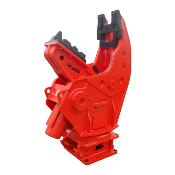
U and G-SERIES SECONDARY
CONCRETE CRUSHERS
MODELS U21J, U21JR, U31J, U31JR
OPERATION AND MAINTENANCE MANUAL
© Copyright 2018 NPK Construction Equipment, Inc.
G Series Crushers Operation Manual 10-18
U45J, U45JR, G7, G18J, G26J, G30JR
"Use Genuine NPK Parts"
"Use Genuine NPK Parts"
7550 Independence Drive
Walton Hills, OH 44146-5541
Phone (440) 232-7900
Toll-free (800) 225-4379
Fax (440) 232-6294
www.npkce.com
U000-9600B U and
Advertisement
Table of Contents


Need help?
Do you have a question about the U Series and is the answer not in the manual?
Questions and answers