Table of Contents
Advertisement
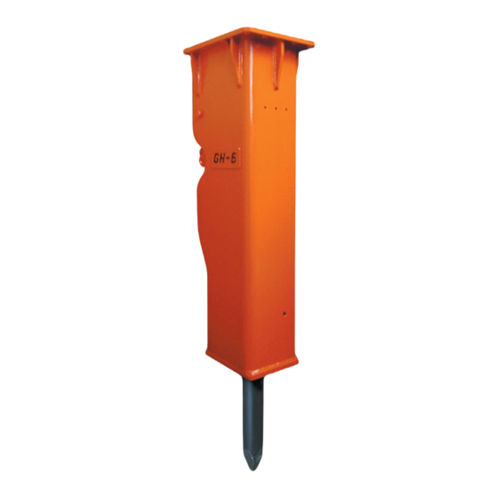
HYDRAULIC HAMMER
OPERATORS MANUAL
GH SERIES HAMMERS
GH06
GH07
© Copyright 2009 NPK Construction Equipment, Inc.
GHS2
GH1
GH2
"Use Genuine NPK Parts"
www.npkce.com
GH3
GH4
GH6
7550 Independence Drive
Walton Hills, OH 44146-5541
Phone (440) 232-7900
Toll-free (800) 225-4379
Fax (440) 232-6294
H050-9640A 03-09.doc
03/09
Advertisement
Table of Contents

Related Manuals for NPK GH06


Summary of Contents for NPK GH06
- Page 1 HYDRAULIC HAMMER OPERATORS MANUAL GH SERIES HAMMERS GH06 GHS2 GH07 "Use Genuine NPK Parts” 7550 Independence Drive Walton Hills, OH 44146-5541 Phone (440) 232-7900 Toll-free (800) 225-4379 Fax (440) 232-6294 © Copyright 2009 NPK Construction Equipment, Inc. www.npkce.com H050-9640A 03-09.doc 03/09...
-
Page 2: Table Of Contents
MOUNTING INSTALLATION ..................11 LUBRICATION ......................12 GREASING PROCEDURE ..................12 CORRECT GREASE AND GREASE INTERVALS ........... 13 NPK HAMMER GREASE ..................15 AUTOLUBE SYSTEMS..................... 15 LUBRICANT TERMS AND DEFINITIONS ..............16 START-UP OPERATION ....................18 HAMMERS THAT ARE NEW, REBUILT, OR HAVE BEEN INACTIVE ....18 BEFORE STARTING THE HAMMER ............... -
Page 3: Safety
WARNING and BASIC OPERATING INSTRUCTIONS decals are included with each NPK hammer and installation kit. Decals must be installed in the cab, visible to the operator while operating the hammer. STAY CLEAR, PRESSURE VESSEL, GAS PRESSURE and TOOL SHARPENING decals are installed on all NPK hammer models. - Page 4 See CARRIER MACHINE COMPATIBILITY section of the NPK instruction manual. 10. Do not make any alterations to the TOOL without authorization from NPK Engineering. 11. Use proper lifting equipment and tools when handling or servicing the HAMMER.
-
Page 5: Introduction
For additional information or help with any problem encountered, please contact your NPK authorized dealer. Whenever repair or replacement of component parts is required, only NPK parts should be used. NPK is not responsible for failures resulting from substitution of parts not sold or approved by NPK. - 4 -... -
Page 6: Carrier Machine Compatibility
Mounting a HAMMER that is too small for the carrier machine can damage the HAMMER, cause tool breakage and void Warranties. Please consult NPK Engineering for specific detailed information. CARRIER WEIGHT lbs. (kg) -
Page 7: Hammer Specifications
FREQUENCY WEIGHT STYLE WORKING CLASS LENGTH ft lb (Kg) in (mm) in (mm) GH06 480 – 1200 500 (225) Skid Steer 1.7 (42) 12.2 (311) 235 (107) Excavator GH07 500 – 1200 550 (250) Skid Steer 1.9 (47) 13.1 (333) 270 (125) Excavator 550 –... -
Page 8: Hydraulic Installation
Typically, the pressure line is arranged on the left side of the boom and the return line on the right side. Flow to the hammer is controlled from an auxiliary valve on the carrier or from an NPK supplied valve. Hydraulic oil, generally, is routed back to the tank thru the carrier’s oil cooler and filter. -
Page 9: Prevention Of Contamination
HYDRAULIC INSTALLATION PREVENTION OF CONTAMINATION ATTENTION 1. A hydraulic hammer is harder on oil than using a bucket, so the oil is apt to deteriorate and breakdown sooner. Neglect of the oil system can not only damage the hydraulic hammer but also cause problems in the carrier which could result in damaged components. -
Page 10: Hydraulic Quick Disconnects
This, again, can cause damage. 3. Most quick disconnects create a restriction in the circuit. NPK Hammers are not back pressure sensitive, but restrictions cause unnecessary heating of the oil. Also, the pressure required to operate the hammer, plus the restriction in the disconnects may push an older, low pressure, carrier machine to the limit of its hydraulic system. - Page 11 HYDRAULIC INSTALLATION HYDRAULIC QUICK DISCONNECTS If hydraulic quick disconnects are used with the NPK Hammer, it is recommended that the following precautions be followed. 1. Periodic inspection of both male and female ends is recommended to ensure the couplers are in good working condition.
-
Page 12: Mounting Installation
MOUNTING INSTALLATION NPK Mounting Installation Kits include the parts required to adapt the NPK HYDRAULIC HAMMER to the carrier. NPK mounting kits include the hammer mounting bracket, flow control valve (if required), and hoses to connect to the carrier hydraulic system. -
Page 13: Lubrication
3. Grease the hammer until grease begins to come out around the tool and lower bushing. 4. Grease hammer at least once an hour, or install an NPK Autolube System. See “Correct Grease and Grease Intervals” for a more exact greasing procedure. -
Page 14: Correct Grease And Grease Intervals
CORRECT GREASE The type of grease used is very important. NPK recommends a lithium soap base EP (Extreme Pressure) NLGI #2 Grease, with Moly (Molybdenum Disulfide) or other surface protecting additives. A high drop point (500° F, 260° C) grease is desirable. - Page 15 LUBRICATION CORRECT GREASE FOR HYDRAULIC HAMMERS MANUFACTURER BRAND NAME Amalie Oil Co. LI-2M Rykotac EP Grease Amoco Amolith Grease 94601 Rykon Premium Grease EP (Grade 94108) Rykon Premium Moly Grease (Grade 94114) Amoco Molylith Grease 92006 Amsoil, Inc. BP Oil, Inc. Bearing Gard-2 Caterpillar Multipurpose Molydbenum Grease (MPGM)
-
Page 16: Npk Hammer Grease
CORRECT GREASE FOR HYDRAULIC HAMMERS NPK HAMMER GREASE NPK now offers hammer grease specially formulated to meet severe job requirements. The grease is available in three different temperature ranges - 350°, 500°, and 2000°. All are compatible with Autolube systems. -
Page 17: Lubricant Terms And Definitions
LUBRICATION LUBRICANT TERMS AND DEFINITIONS TERM DEFINITION ADHESIVE The ability of grease, gear lubricant or oil to cling to metal. ANTI WEAR AGENTS Used to help combat metal-to-metal contact, thus reducing wear. The ability of grease, gear lube or oil to cling to itself, COHESIVE thus resisting tearing apart. - Page 18 LUBRICATION LUBRICANT TERMS AND DEFINITIONS TERM DEFINITION A container for keeping a supply of working fluid in a RESERVOIR hydraulic system. VIBRATION A quivering or trembling motion. VISCOSITY Is the actual SAE weight of the product. Example motor oils come in 10, 20, 30, 40, 50 and 15/40 SAE weight. The viscosity designation of a lubricant indicates its internal resistance to flow.
-
Page 19: Start-Up Operation
1. Check the nitrogen gas pressure. The nitrogen gas pre-charge is factory checked before shipment. However, it is recommended the pressure be checked before using the NPK HYDRAULIC HAMMER for the first time. For the inspection procedure, see CHECKING THE GAS PRESSURE, page 37. -
Page 20: Before Starting The Hammer
Before operating the NPK HYDRAULIC HAMMER, be sure to perform the specified ROUTINE INSPECTION, see page 26. Warm up the NPK HYDRAULIC HAMMER, see below, and the base machine in accordance with the machine manufacturer’s instruction manual. This is especially important during cold weather operation. -
Page 21: Operation
OPERATION SAFE OPERATING INSTRUCTIONS DO NOT OPERATE THE HAMMER WITHOUT AN IMPACT RESISTANT CAB WINDOW OR SHIELD IN PLACE BEWARE OF FLYING DEBRIS FROM THE HAMMER TOOL POINT An impact resistant cab window or shield must be in place to protect the operator. Do not use the hammer in a way as to cause rock, etc. -
Page 22: Operating Techniques & Precautions
NPK HYDRAULIC HAMMER. Applying excessive force to the hammer will raise the carrier too high and jolt the operator when the material breaks. Let the NPK HYDRAULIC HAMMER do the work. AVOID BLANK HAMMERING As soon as the material is broken, release the control lever or pedal to prevent unnecessary blank hammering. - Page 23 OPERATION OPERATING TECHNIQUES & PRECAUTIONS ATTENTION DO NOT SLANT HAMMER For the most efficient demolition, align the direction of force (51) from the boom with the penetration direction (52) of the tool (HH). Failure to do this decreases the transfer of energy from the piston to the rock and increases the bending forces at the fulcrum of the tool.
- Page 24 OPERATION OPERATING TECHNIQUES & PRECAUTIONS ATTENTION DO NOT USE THE HAMMER TOOL AS A PRY BAR Excessive prying cause premature bushing wear and tool or tie rod breakage. When hammering materials that allow the tool to penetrate before breaking, move the hammer slightly fore and aft to create a cone-shaped hole.
- Page 25 OPERATION OPERATING TECHNIQUES & PRECAUTIONS ATTENTION DO NOT DROP THE HAMMER RAPIDLY ON AN OBJECT Remember, the hydraulic hammer is heavier than an empty bucket and will move faster than expected. DO NOT USE THE HAMMER BRACKET MOVE LARGE OBJECTS Do not use the hammer bracket for purposes other than for what is was intended.
- Page 26 Underwater operation will damage the hammer and allow water to enter the hydraulic system. The hammer can be modified for underwater operation - contact the NPK Dealer for more information. DO NOT SUBMERGE A HOT TOOL IN WATER The tip of the tool may be hot from operation.
-
Page 27: Routine Inspection And Maintenance
Check for oil leaks, loose clamps and hose abrasion. HYDRAULIC OIL MAINTAIN A CLEAN HYDRAULIC SYSTEM If non-petroleum oil is used, contact NPK Service Department for compatibility. Keep hoses clean and capped when dismounting or storing hammer. Change oil and filters as recommended by carrier manufacturer. Periodic oil sampling is recommended. -
Page 28: Weekly Inspection
WEEKLY INSPECTION 1. WELDS Check for cracks, repair as necessary. Consult your authorized NPK Dealer or NPK Service Department for additional information. 2. TOOL RETAINING PIN Remove the retaining pin and inspect for peening caused by excessive blank hammering. If necessary, grind edges smooth as shown in TOOL RETAINING PIN INSPECTION, see page 32. -
Page 29: Tools
TOOLS STANDARD TOOLS DEMOLITION TOOL SHAPE APPLICATIONS • Trenching CHISEL (FX) • Cutting casting gates The cross cut (FX) tool • Breaking oversize cuts at right angle, or • General demolition crosswise, to the stick and boom of the excavator. •... -
Page 30: Changing The Tool
TOOLS CHANGING THE TOOL REMOVAL 1. Remove the retaining pin ring (E) by using pliers or a screwdriver (t22), see Figures 1 and 2. It will easily come out if pulled at an angle as shown in Figure 2. Figure 1 Figure 2 2. -
Page 31: Maximum Tool To Tool Bushing Clearance
Measure the tool to bushing gap (d15) with the hammer horizontal, as illustrated below. If the clearance is at or greater than the charted maximum clearance, then move on to the next steps. MAXIMUM CLEARANCE MODEL INCH (mm) (d15) GH06 1/4 (6.5) GH07 1/4 (6.5) 1/4 (6.5) GH2 / GHS2 1/4 (6.5) - Page 32 NEW BUSHING MAXIMUM BUSHING MODEL INSIDE DIAMETER INSIDE DIAMETER INCH (mm) INCH (mm) GH06 1.67 (42.4) 1.87 (47.4) GH07 1.87 (47.4) 2.07 (52.6) 2.26 (57.4) 2.46 (62.6) GH2 / GHS2 2.61 (66.4)
-
Page 33: Tool Retaining Pin Inspection
Deformation may occur on the retaining pin in the tool contact area (AN). If this area is mushroomed, the retaining pin may become difficult to remove. Dress areas shown (AN) with a grinder. HAMMER MODELS GH06, GH07, GH1, GH2 / GHS2, GH3, GH4, GH6 - 32 -... -
Page 34: Tool Inspection
TOOLS TOOL INSPECTION 1. Deformation may occur on the tool in the retaining pin contact area (15) or thrust surface (31). If these areas are mushroomed, the tool may become difficult to remove from the tool holder. Dress with a grinder. 2. -
Page 35: Torque Values For Hammer Fasteners
If hammer or hammer bracket fasteners are found to be loose, use the following charts. If repairs are to be made, see the NPK Hydraulic Hammer Service Manual. Medium strength thread adhesive should be used on all the valve assembly bolts and the gas charge valve. -
Page 36: Gas Charge
See the chart “Ambient Temperature” below. ATTENTION DO NOT OVERCHARGE THE HAMMER! Exceeding the gas pre-charge specifications can result in damaging hammer components. The NPK WARRANTY does not cover failures resulting from exceeding the specified nitrogen gas pressure. NITROGEN GAS PRE-CHARGE AT AMBIENT TEMPERATURE... -
Page 37: Gas Charging Kit
(g13), pin (g15) should move downward approximately 1/8” as the T-handle (g2) is turned clockwise. NOTE: If the pin (g14) in the center of the NPK gas charge valve (g1) is bent, checking and charging the hammer may not be possible. - 36 -... -
Page 38: Checking The Gas Pressure
THE HAMMER MUST NOT BE RESTING ON THE POINT. 2. Remove the charge valve cap (M1). 3. Turn the NPK charging adapter T- handle (g2) full counterclockwise. 4. MODELS GH06, GH07, GH1, 4. - Page 39 9. Slowly loosen the charge adapter cap to relieve the nitrogen gas pressure trapped in the charge valve. 10. Remove the charge adapter from the hammer charge valve. 11. Remove NPK adapter part no. 30604100. 12. Reinstall existing plug. - 38 -...
-
Page 40: Charging The Hammer
GAS CHARGE CHARGING THE HAMMER USE NITROGEN GAS ONLY . STAY CLEAR OF THE TOOL WHILE CHARGING THE HAMMER WITH GAS. The tool may be impacted by the piston and forced out abruptly. PROCEDURE 1. Carry out steps 1 thru 4 of CHECKING THE GAS PRESSURE, see page 37. 2. -
Page 41: Discharging The Gas Pressure
1. Remove the charge valve cap (M1). 2. Turn the NPK charging adapter T- handle (g2) counterclockwise until it stops. 3. The NPK GH06, GH07, GH1 and 4. Install the NPK charging adapter (g1) GH2/GHS2 hydraulic hammers have a on the hammer charge valve (M). - Page 42 GAS CHARGE DISCHARGING THE GAS PRESSURE PROCEDURE Remove the valve cap only, not the charge valve assembly! 5. Tighten the charging 6. Turn the T-handle (g2) 7. Loosen the charge adapter adapter cap (g6). clockwise. As the T- cap (g6) VERY SLOWLY. handle is screwed in, a pressure will...
-
Page 43: Warranty Registration For New Units
WARRANTY REGISTRATION FOR NEW UNITS Complete and send to NPK after installation or complete on line at www.npkce.com Online warranty registration can be done by the dealer or the end user. The registration can be done in any of the following ways. -
Page 44: Warranty Statement
WARRANTY STATEMENT - 43 -... -
Page 45: Storage Of Hydraulic Hammer
(t20). Be sure the tool is liberally greased and the hydraulic hoses are capped (AO). Cover with a waterproof tarp (t21), not shown. If the NPK HYDRAULIC HAMMER is not to be used for a long period of time (months), it is recommended the gas pressure be discharged (M). The tool (HH) should be removed, and the piston pushed all the way in. -
Page 46: Notes And Records
NOTES AND RECORDS NPK HYDRAULIC HAMMER MODEL NUMBER _______________ SERIAL NUMBER _______________ NPK INSTALLATION KIT NUMBER ___________________________ CARRIER MANUFACTURER MODEL NUMBER SERIES SERIAL NUMBER DATE OF INSTALLATION _________________ DATE OF 20 HOUR INSPECTION ___________ WARRANTY REGISTRATION SENT - 45 -... - Page 47 © Copyright 2009 NPK Construction Equipment, Inc. www.npkce.com H050-9640A 03-09.doc 03/09...
Need help?
Do you have a question about the GH06 and is the answer not in the manual?
Questions and answers