Table of Contents
Advertisement
HYDRAULIC HAMMER
OPERATORS MANUAL
GH SERIES HAMMERS
© Copyright 2014 NPK Construction Equipment, Inc.
Hyd Ham Operators Manual 4-14
GH7
GH9
GH10
GH12
GH15
"Use Genuine NPK Parts"
GH18
GH23
GH30
GH40
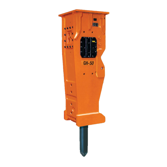
GH50
7550 Independence Drive
Walton Hills, OH 44146-5541
www.npkce.com
H050-9630G GH7 - GH50
Phone (440) 232-7900
Toll-free (800) 225-4379
Fax (440) 232-6294
Advertisement
Table of Contents

Related Manuals for NPK GH7


Summary of Contents for NPK GH7
- Page 1 GH40 GH15 GH50 "Use Genuine NPK Parts” 7550 Independence Drive Walton Hills, OH 44146-5541 Phone (440) 232-7900 Toll-free (800) 225-4379 Fax (440) 232-6294 © Copyright 2014 NPK Construction Equipment, Inc. www.npkce.com H050-9630G GH7 - GH50 Hyd Ham Operators Manual 4-14...
-
Page 2: Table Of Contents
CHANGING THE TOOL ......................... 38 MAXIMUM TOOL TO TOOL BUSHING CLEARANCE ................39 CHISEL TOOL RESHARPENING ......................41 TOOLS ................................ 42 STANDARD LENGTH FOR NPK TOOLS ....................42 TOOL RETAINING PIN INSPECTION ....................43 TOOL INSPECTION ..........................44 - 1 -... - Page 3 TOOL BREAKAGE DUE TO CORROSION ................... 54 TOOL BREAKAGE DUE TO DEFECTIVE MATERIAL ................54 TORQUE VALUES FOR HAMMER FASTENERS ..................55 HAMMER BRACKET – GH7 THROUGH GH50 ..................56 GAS CHARGE ............................57 NITROGEN GAS PRESSURE ....................... 57 GAS CHARGING KIT ..........................57 CHECKING THE GAS PRESSURE .......................
-
Page 4: Safety
WARNING and BASIC OPERATING INSTRUCTIONS decals are included with each NPK hammer and installation kit. Decals must be installed in the cab, visible to the operator while operating the hammer. STAY CLEAR, PRESSURE VESSEL, GAS PRESSURE and TOOL SHARPENING decals are installed on all NPK hammer models. - Page 5 See CARRIER MACHINE COMPATIBILITY section of the NPK Service Manual. 10. Do not make any alterations to the TOOL without authorization from NPK Engineering. 11. Use proper lifting equipment and tools when handling or servicing the HAMMER.
-
Page 6: Introduction
NPK authorized dealer. Whenever repair or replacement of component parts is required, only NPK parts should be used. NPK is not responsible for failures resulting from substitution of parts not sold or approved by NPK. This manual will also assist NPK Dealers and Customers to obtain the longest possible life from the NPK Demolition Tools. -
Page 7: Carrier Machine Compatibility
Verify carrier stability with HAMMER before transport or operation. Mounting a HAMMER that is too small for the carrier machine can damage the HAMMER, cause tool breakage and void Warranties. Please consult the NPK Sales Department for specific detailed information. CARRIER WEIGHT lbs. (kg) -
Page 8: Hammer Specifications
HAMMER SPECIFICATIONS IMPACT TOOL HAMMER ENERGY FREQUENCY WORKING WORKING MODEL CLASS WEIGHT LENGTH ft lb (Kg) in (mm) in (mm) 2500 400 - 750 2900 (1320) 4.6 (116) 23 (583) 3000 500 - 670 3600 (1635) 5.0 (126) 24 (608) GH10 4000 400 - 550... -
Page 9: Hammer Serial Number Location
HAMMER SERIAL NUMBER LOCATION NPK HAMMER MODELS GH7 through GH50 The serial number location (sn1) is right of center on the body above the Autolube port. - 8 -... -
Page 10: Hydraulic Installation
Typically, the pressure line is arranged on the left side of the boom and the return line on the right side. Flow to the hammer is controlled from an auxiliary valve on the carrier or from an NPK supplied valve. Hydraulic oil is routed back to the tank through the carrier’s oil cooler and filter. -
Page 11: Prevention Of Contamination
HYDRAULIC INSTALLATION ATTENTION PREVENTION OF CONTAMINATION 1. A hydraulic hammer is harder on oil than using a bucket, so the oil is apt to deteriorate and breakdown sooner. Neglect of the hydraulic oil can not only damage the hydraulic hammer but also cause problems in the carrier, which could result in damaged components. -
Page 12: Hydraulic Quick Disconnects
This, again, can cause damage. 3. Most quick disconnects create a restriction in the circuit. NPK Hammers are not back pressure sensitive, but restrictions cause unnecessary heating of the oil. Also, the pressure required to operate the hammer, plus the restriction of the disconnects may push an older, low pressure, carrier machine to the limit of its hydraulic system. - Page 13 HYDRAULIC INSTALLATION HYDRAULIC QUICK DISCONNECTS If hydraulic quick disconnects are used with the NPK Hammer, it is recommended that the following precautions be followed. 1. Periodic inspection of both male female ends (32) recommended ensure couplers are in good working condition.
-
Page 14: Mounting Installation
MOUNTING INSTALLATION NPK Mounting Installation Kits include the parts required to adapt the NPK HYDRAULIC HAMMER to the carrier. NPK mounting kits include the top bracket (m7), flow control valve (if required), and hoses to connect to the carrier hydraulic system. -
Page 15: Mounting To The Carrier
MOUNTING INSTALLATION MOUNTING TO THE CARRIER 1. Place the hammer horizontal on wood blocks (t20), as shown. 2. Align the boom pin holes. Install the stick pin (m1) before the cylinder link pin (m2). 3. Clean away any dirt found on the hose connections and connect hoses. -
Page 16: Lubrication
LUBRICATION GREASING PROCEDURE Manual greasing for hammers without AUTOLUBE system IMPORTANT: 1. The hammer must be in a vertical position with downforce applied to push the tool all the way in. This prevents grease from entering piston impact area. 2. Turn the machine off. 3. -
Page 17: Correct Grease And Grease Intervals
CORRECT GREASE The type of grease used is very important. NPK recommends a lithium soap base EP (Extreme Pressure) NLGI #2 Grease, with Moly (Molybdenum Disulfide) or other surface protecting additives. A high drop point 500° F (260° C) grease is desirable. - Page 18 LUBRICATION CORRECT GREASE FOR HYDRAULIC HAMMERS MANUFACTURER BRAND NAME LI-2M Amalie Oil Co. Amoco Rykotac EP Grease Amolith Grease 94601 Rykon Premium Grease EP (Grade 94108) Rykon Premium Moly Grease (Grade 94114) Amoco Molylith Grease 92006 Amsoil, Inc. BP Oil, Inc. Bearing Gard-2 Caterpillar Multipurpose Molydbenum Grease (MPGM)
-
Page 19: Autolube Systems
NPK GH series hammer models have a connection port (26) for an automatic greasing system. Refer to the NPK AUTOLUBE Instruction Manual for details. - 18 -... -
Page 20: Autolube Grease Line Pre-Filling
2. Turn the machine off. 3. Fill the NPK Autolube pump reservoir with a power greaser through the fill fitting on the side of the pump, or from the top by removing the fill cover. Use a premium quality grade EP-2, high temperature grease with wear inhibiting additive. - Page 21 LUBRICATION AUTOLUBE GREASE LINE PRE-FILLING 8. Pump grease through the grease line (29) until a steady stream of grease (28) is realized at the opposite (hammer) end. 9. Re-attach the grease line (29) to the hammer (KK). 10. Pump twenty more shots of grease into the grease line (29).
- Page 22 LUBRICATION AUTOLUBE GREASE LINE PRE-FILLING G100-8050 Hose Fill Assembly B160-4010 Grease Fitting – ¼” NPT male K301-6620 Male x Female Adapter - #6 JIC male x ¼” NPT female - 21 -...
-
Page 23: Lubricant Terms And Definitions
LUBRICATION LUBRICANT TERMS AND DEFINITIONS TERM DEFINITION The ability of grease, gear lubricant or oil to cling to ADHESIVE metal. ANTI WEAR AGENTS Used to help combat metal-to-metal contact, thus reducing wear. COHESIVE The ability of grease, gear lube or oil to cling to itself, thus resisting tearing apart. - Page 24 LUBRICATION LUBRICANT TERMS AND DEFINITIONS TERM DEFINITION A container for keeping a supply of working fluid in a RESERVOIR hydraulic system. A quivering or trembling motion. VIBRATION VISCOSITY Is the actual SAE weight of the product. Example motor oils come in 10, 20, 30, 40, 50 and 15/40 SAE weight. The viscosity designation of a lubricant indicates its internal resistance to flow.
-
Page 25: Start-Up Operation
1. Check the nitrogen gas pressure. The nitrogen gas pre-charge is factory checked before shipment. However, it is recommended the pressure be checked before using the NPK hydraulic hammer for the first time. See CHECKING THE GAS PRESSURE section for procedure. -
Page 26: Before Starting The Hammer
Before operating the NPK hydraulic hammer, be sure to perform the specified routine inspection in the ROUTINE INSPECTION AND MAINTENANCE section of this manual. Warm up the NPK hydraulic hammer, see below, and the carrier machine in accordance with the machine manufacturer’s instruction manual. This is especially important during cold weather operation. -
Page 27: Operation
OPERATION SAFE OPERATING INSTRUCTIONS DO NOT OPERATE THE HAMMER WITHOUT AN IMPACT RESISTANT CAB WINDOW OR SHIELD IN PLACE BEWARE OF FLYING DEBRIS FROM THE HAMMER TOOL POINT An impact resistant cab window or shield must be in place to protect the operator. DO NOT USE THE HAMMER AS A HOIST The hammer is not intended to lift an... -
Page 28: Operating Techniques & Precautions
TOOL Raise the front of the machine slightly (104) by applying downforce on the demolition tool. Press the control lever or the foot pedal to start the NPK HYDRAULIC HAMMER. Applying excessive force hammer will raise the carrier too high and jolt the operator when the material breaks. - Page 29 OPERATION OPERATING TECHNIQUES & PRECAUTIONS DO NOT SLANT HAMMER For the most efficient demolition, align the direction of force (51) from the boom with the penetration direction (52) of the tool (HH). Failure to do this decreases the transfer of energy from the piston to the rock and increases the bending forces at the fulcrum of the tool.
- Page 30 OPERATION OPERATING TECHNIQUES & PRECAUTIONS DO NOT USE THE HAMMER TOOL AS A PRY BAR Excessive prying cause premature bushing wear and tool or tie rod breakage. When hammering materials that allow tool penetrate before breaking, move the hammer slightly fore and aft to create a cone-shaped hole.
- Page 31 OPERATION OPERATING TECHNIQUES & PRECAUTIONS DO NOT DROP THE HAMMER RAPIDLY ON AN OBJECT Remember, the hydraulic hammer is heavier than an empty bucket and will move faster than expected. DO NOT USE THE HAMMER BRACKET MOVE LARGE OBJECTS Do not use the hammer bracket for purposes other than for what is was intended.
- Page 32 Underwater operation will damage the hammer and allow water to enter the hydraulic system. The hammer can be modified for underwater operation - contact NPK at 800-225-4379 for more information. DO NOT SUBMERGE A HOT TOOL IN WATER The tip of the tool may be hot from operation.
-
Page 33: Impact Energy Transmission Through Tools
IMPACT ENERGY TRANSMISSION THROUGH TOOLS A hydraulic hammer converts hydraulic power to kinetic energy. The kinetic energy is delivered by the hammer piston to the tool as an impact force. Unlike a slowly transmitted force, such as the force with which a hydraulic cylinder extends, the impact force produced by the piston when it hits the tool is transmitted through the interior of the tool as a compression stress wave until it reaches the rock, concrete, or other material that the tool is about to break. -
Page 34: Impact Stress Waves At The End Of The Tool
IMPACT ENERGY TRANSMISSION THROUGH TOOLS IMPACT STRESS WAVES AT THE END OF THE TOOL When the tool is in contact with the material to be broken, most of the compression stress waves are transferred to the material, and the energy of the compression waves then... -
Page 35: Routine Inspection And Maintenance
Do not hardface or sharpen the tool point with a cutting torch. Excessive heat from torching or welding causes embrittlement, breakage, and flying pieces. Re-sharpen only with a surface grinder or milling machine using sufficient cooling. Please consult your authorized NPK Dealer or NPK Service Department for additional information. - 34 -... -
Page 36: Weekly Inspection
WEEKLY INSPECTION 1. WELDS Check for cracks, repair as necessary. Consult your authorized NPK Dealer or NPK Service Department for additional information. 2. TOOL RETAINING PIN Remove the retaining pin and inspect for peening caused by excessive blank hammering. If necessary, grind edges smooth as shown in TOOL RETAINING PIN INSPECTION section. -
Page 37: Types And Applications Of Tool
TYPES AND APPLICATIONS OF TOOL STANDARD TOOLS DEMOLITION TOOL SHAPE APPLICATIONS Trenching CHISEL (FX) Cutting casting gates The cross cut (FX) tool Breaking oversize cuts at right angle, or General demolition crosswise, to the stick and boom of the excavator. -
Page 38: Tool Identification
TOOL IDENTIFICATION NPK demolition tools can be identified by the numbers found stamped in the retaining pin slot area. These numbers must be included in all warranty correspondences regarding a broken tool. Photos must also be included. - 37 -... -
Page 39: Changing The Tool
TOOLS CHANGING THE TOOL REMOVAL 1. Remove the retaining ring by using pliers or screwdrivers, see Figures 1 and 2. It will easily come out if pulled at an angle as shown in Figure 2. 2. Screw an M12 bolt or cap screw into the retainer pin. 3. -
Page 40: Maximum Tool To Tool Bushing Clearance
Step 1 Measure the tool to bushing gap (d15) with the hammer horizontal, as illustrated below. If the clearance is at or greater than the charted maximum clearance, consult the NPK Hydraulic Hammer Service Manual to determine which component requires replacement. - Page 41 TOOLS MAXIMUM TOOL TO TOOL BUSHING CLEARANCE Step 3 Measure the inside diameter of the lower and upper tool bushings. The maximum tool bushing inside diameter is compared to a new tool only. If the tool bushing dimensions are at or above the charted value, the bushing must be replaced. NEW BUSHING MAXIMUM BUSHING MODEL...
-
Page 42: Chisel Tool Resharpening
TOOLS CHISEL TOOL RESHARPENING Worn chisel tools can be re-sharpened by machining according to the dimensions below. DO NOT hardface or sharpen the tool point with a cutting torch! Re-sharpen only by milling or grinding, using sufficient coolant. MODEL NO. inch inch 4.50... -
Page 43: Tools
TOOLS STANDARD LENGTH FOR NPK TOOLS d23 = Length of tool from top to bottom. d22 = Length of tool exposed from bottom of tool bushing to end of tool. d16 = Diameter of bearing surface of tool. NEW TOOL... -
Page 44: Tool Retaining Pin Inspection
TOOLS TOOL RETAINING PIN INSPECTION The tool retaining pin (D) serves to keep the tool in the hammer when the hammer is raised off the ground for repositioning. Additionally, the retaining pin will become worn during normal use. Figure “A” shows the retaining pin when it is new. Note: the two guide grooves (AN). -
Page 45: Tool Inspection
TOOLS TOOL INSPECTION 1. Deformation may occur on the tool in the retaining pin contact area (15) or thrust surface (31). If these areas are mushroomed, the tool may become difficult to remove from the tool holder. Dress with a grinder. 2. -
Page 46: Tool Warranty
Custom or special application tools which are excluded from warranty. NPK RESPONSIBILITY NPK will, at its option, replace with a new or reconditioned tool, any warranted tool that fails by reason of defective material or workmanship, free of charge delivered at a place of business of an NPK Dealer. - Page 47 Installations not approved by NPK. Use of parts not sold by NPK. THE USE OF “WILL FIT” PARTS WILL VOID THE WARRANTIES OF ANY AND ALL PARTS DAMAGED AS A RESULT OF THE FAILURE OF THE “WILL FIT” PARTS.
-
Page 48: Tool Breakage
1. Properly position the hammer so as not to develop a bending moment in the tool. 2. Apply sufficient grease to prevent the tool from developing cracks due to galling. This will also assure longer tool bushing life. WARRANTY NPK Warranty does not apply to this type of failure. - 47 -... -
Page 49: Tool Breakage Due To Excessive Wear Of The Tool Holder Bushings
TOOL BREAKAGE TOOL BREAKAGE DUE TO EXCESSIVE WEAR OF THE TOOL HOLDER BUSHINGS If the hydraulic hammer is used with tool holder bushings worn beyond specifications, the tool will be at an excessive angle to the piston at the moment of impact. The entire force of the piston is concentrated in a small area of the impact head of the tool (Fig. - Page 50 GH7, GH9, GH10 3/8 (10) GH12, GH15, 1/2 (13) GH18 GH23, GH30, 5/8 (16) GH40, GH50 Tool Bushing Tool d15. Clearance d16. Tool Diameter WARRANTY NPK Warranty does not cover tool failure caused by worn tool holder bushings. - 49 -...
-
Page 51: Chipping In Retaining Pin Slot
TOOL BREAKAGE A. CHIPPING IN RETAINING PIN SLOT The tool may become chipped at the upper end of the retaining pin slot where it contacts the retaining pin. Free standing oversize rock may sometimes be broken with only a few hammer blows. If the operator does not stop hammering immediately, the tool will hit the retaining pin (blank hammering), and can chip the upper end of the retaining pin slot. -
Page 52: Deformation Of The Tool Tip
TOOL BREAKAGE C. DEFORMATION OF THE TOOL TIP Hammering continuously in one position for over 30 seconds will overheat the tool tip. If this is done repeatedly, the tip will lose temper and mushroom. Overheating wears the tip faster and can allow the tip to chip. PREVENTATIVE MEASURES Move tool position if material is not broken after 30 seconds of hammering. -
Page 53: Chipping Of A Moil Point Tool Tip
Overheating tool by hammering for more than 30 seconds in one spot can cause chipping. PREVENTATIVE MEASURES Use correct size hammer for job conditions. Do not hammer for more than 30 seconds without moving hammer. WARRANTY NPK Warranty does not cover types A, B, C, D and E problems. - 52 -... -
Page 54: Temperature Related Tool Problems
Warm the tool before starting to operate the hammer when temperature is below 32° F, (0° C). WARRANTY NPK Warranty does not cover this type of failure. EXCESSIVE SLANT HAMMERING When constant slant hammering is performed while using boom downforce, the tool may become deformed as shown in the picture below. -
Page 55: Tool Breakage Due To Corrosion
Dry the tool and coat it with grease to protect it from corrosion. WARRANTY NPK Warranty does not cover this type of failure. TOOL BREAKAGE DUE TO DEFECTIVE MATERIAL If metal fatigue originates from the interior, not the exterior, the material has some defect and fatigue will break the tool. -
Page 56: Torque Values For Hammer Fasteners
155 (210) GH50 1400 (1900) 1400 (1900) 155 (210) See HAMMER DISASSEMBLY AND ASSEMBLY – TOOLS AND EQUIPMENT section of the Service Manual for NPK hex key wrench part numbers. HEX HEAD BOLTS TOP ADAPTER HAMMER BRACKET RUBBER MOUNTS BRACKET... -
Page 57: Hammer Bracket - Gh7 Through Gh50
HAMMER FASTENER TORQUE HAMMER BRACKET – GH7 THROUGH GH50 The bolt torque for the lower support block bolt in Location (L2) has been reduced. Please see the following chart showing the torque values. Bolts marked Location (L1) are not affected and the standard torque remains the same. Lube all bolts. -
Page 58: Gas Charge
GH50 GAS CHARGING KIT ALL NPK HYDRAULIC HAMMERS are furnished with the following gas charging kit. In addition, a nitrogen tank and pressure regulator valve (not furnished with the hammer) are required. These can be obtained from your local welding supply house. A regulator valve is available from NPK. -
Page 59: Checking The Gas Pressure
3. Turn the NPK charge adapter T-handle (g2) to a full counterclockwise position. 4. Install the NPK charge adapter (g1) onto the hammer charge valve located on the hammer gas head (L). 5. Tighten the charge adapter cap (g6). - Page 60 GAS CHARGE CHECKING THE GAS PRESSURE 6. Turn the T-handle (g2) clockwise. As the T-handle is screwed in, a resistance is encountered. By turning the T-handle further, the nitrogen gas pressure will be indicated on the pressure gauge (g8). Stop turning the T-handle when the gauge reads pressure.
-
Page 61: Charging The Hammer
GAS CHARGE CHARGING THE HAMMER USE NITROGEN GAS ONLY STAY CLEAR TOOL WHILE CHARGING THE HAMMER WITH GAS. The tool may be impacted by the piston and forced out abruptly. PROCEDURE 1. Carry out steps 1 thru 4 of CHECKING THE GAS PRESSURE. 2. - Page 62 GAS CHARGE CHARGING THE HAMMER Nitrogen gas may be trapped in the hose. Loosen fittings slowly to release pressure! 10. Remove the charge adapter from the hammer charge valve. 11. Replace the charge valve cap - 61 -...
-
Page 63: Discharging The Gas Pressure
GAS CHARGE DISCHARGING THE GAS PRESSURE PROCEDURE 1. Remove charge 2. Turn the NPK charge 3. Install the NPK charge valve cap (M1) from the adapter T-handle (g2) to adapter (g1) onto charge valve (M). a full counterclockwise hammer charge valve position. -
Page 64: Warranty Registration For New Units
WARRANTY REGISTRATION FOR NEW UNITS Complete and send to NPK after installation or complete online at www.npkce.com. Online warranty registration can be done by the dealer or the end user. The registration can be done in any of the following ways: 1. -
Page 65: Storage Of Hydraulic Hammer
(t20). Be sure the tool (HH) is liberally greased and the hydraulic hoses (AO) are capped. Cover with a waterproof tarp (t21), not shown. If the NPK HYDRAULIC HAMMER is not to be used for a long period of time (months), the following storage procedure is recommended: 1. -
Page 66: Warranty Statements
WARRANTY STATEMENTS - 65 -... - Page 67 WARRANTY STATEMENTS - 66 -...
- Page 68 WARRANTY STATEMENTS - 67 -...
- Page 69 WARRANTY STATEMENTS - 68 -...
-
Page 70: Notes And Records
NOTES AND RECORDS NPK HYDRAULIC HAMMER MODEL NUMBER _______________ SERIAL NUMBER _______________ NPK INSTALLATION KIT NUMBER ________________________ CARRIER MANUFACTURER MODEL NUMBER SERIES SERIAL NUMBER DATE OF INSTALLATION _________________ DATE OF 20 HOUR INSPECTION ___________ WARRANTY REGISTRATION SENT - 69 -... - Page 71 © Copyright 2014 NPK Construction Equipment, Inc. www.npkce.com H050-9630G GH7 - GH50 Hyd Ham Operators Manual 4-14...
Need help?
Do you have a question about the GH7 and is the answer not in the manual?
Questions and answers