Table of Contents
Advertisement
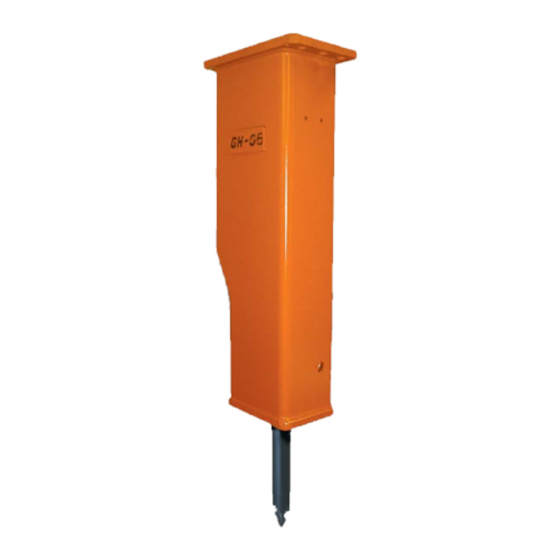
HYDRAULIC HAMMER
SERVICE MANUAL
GH SERIES HAMMERS
GH06
GH07
GH1
GH2/GHS2
© Copyright 2009 NPK Construction Equipment, Inc.
"Use Genuine NPK Parts"
GH3
GH4
GH6
Walton Hills, OH 44146-5541
www.npkce.com
7550 Independence Drive
Phone (440) 232-7900
Toll-free (800) 225-4379
Fax (440) 232-6294
H055-9640A.doc
03/09
Advertisement
Table of Contents

Subscribe to Our Youtube Channel
Related Manuals for NPK GH Series


Summary of Contents for NPK GH Series
- Page 1 HYDRAULIC HAMMER SERVICE MANUAL GH SERIES HAMMERS GH06 GH07 GH2/GHS2 “Use Genuine NPK Parts” 7550 Independence Drive Walton Hills, OH 44146-5541 Phone (440) 232-7900 Toll-free (800) 225-4379 Fax (440) 232-6294 © Copyright 2009 NPK Construction Equipment, Inc. www.npkce.com H055-9640A.doc 03/09...
-
Page 2: Safety
WARNING and BASIC OPERATING INSTRUCTIONS decals are included with each NPK hammer and installation kit. Decals must be installed in the cab, visible to the operator while operating the hammer. STAY CLEAR, PRESSURE VESSEL, GAS PRESSURE and TOOL SHARPENING decals are installed on all NPK hammer models. - Page 3 8. Operate HAMMER from operator’s seat only. 9. Match HAMMER size to carrier according to NPK recommendations, see page 7. The carrier must be stable during hammer operation and during transport. 10. Do not make any alterations to the TOOL without authorization from NPK Engineering.
-
Page 4: Table Of Contents
CONTENTS SAFETY ........................1 INTRODUCTION.....................5 BASIC OPERATING INSTRUCTIONS..............5 PRECAUTIONS FOR USING THE NPK HYDRAULIC HAMMER ......6 CARRIER MACHINE COMPATIBILITY ..............7 HAMMER SPECIFICATIONS .................8 STRUCTURE ......................9 HAMMER SERIAL NUMBER LOCATION...............11 PRINCIPLE OF OPERATION .................12 HYDRAULIC INSTALLATION .................13 MOUNTING INSTALLATION ..................17 ROUTINE INSPECTION AND MAINTENANCE............18 WEEKLY INSPECTION ..................19... - Page 5 CONTENTS MAXIMUM TOOL TO TOOL BUSHING CLEARANCE ...........84 NPK HYDRAULIC HAMMER IMPACT BUSHINGS ..........86 TOOL INSPECTION....................87 CHISEL TOOL RESHARPENING ................88 STANDARD LENGTH FOR NPK TOOLS ...............89 RETAINING PIN......................90 LUBRICATION ......................91 AUTOLUBE/UNDERWATER PORT IDENTIFICATION ..........94 TOOL BUSHING REPLACEMENT .................95 TOOL HOLDER BUSHING BORE REPAIR............98 TOOL HOLDER ......................101...
-
Page 6: Introduction
INTRODUCTION NPK is a leading manufacturer of boom mounted HYDRAULIC HAMMERS, and has the most complete product line available anywhere. The success of NPK is due to our commitment to quality, dependability and long life. The HYDRAULIC HAMMER has many unique designed features and it is a company philosophy that the NPK HYDRAULIC HAMMER can be brought to "like new”... -
Page 7: Precautions For Using The Npk Hydraulic Hammer
• Operate the hammer in a safe manor. Read the NPK Hydraulic Hammer Operators Manual. If additional safety information is needed, consult the AEM Hydraulic Mounted Safety Manual. To request a free copy, please contact NPK at 800-225-4379 or e-mail us at www.npkce.com. - 6 -... -
Page 8: Carrier Machine Compatibility
Mounting a HAMMER that is too small for the carrier machine can damage the HAMMER, cause tool breakage and void Warranties. Please consult NPK Engineering for specific detailed information. CARRIER WEIGHT lbs. (kg) -
Page 9: Hammer Specifications
HAMMER SPECIFICATIONS HAMMER IMPACT WORKING MOUNTING TOOL MODEL FREQUENCY WEIGHT STYLE ENERGY WORKING CLASS LENGTH ft lb (Kg) in (mm) in (mm) GH06 480 – 1200 500 (225) Skid Steer 1.7 (42) 12.2 (311) 235 (107) Excavator GH07 500 – 1200 550 (250) Skid Steer 1.9 (47) -
Page 10: Structure
STRUCTURE STRUCTURAL DRAWING MODELS GH06 – GH3 MAIN BODY DRAIN PLUG TOOL HOLDER RETAINING PIN RETAINING RING UPPER TOOL BUSHING (GH3 ONLY) LOWER TOOL BUSHING SPACER SECTION GAS HEAD CHARGE VALVE PISTON MAIN BODY SLEEVE (B) TOP NUT WASHER BOTTOM NUT VALVE BODY VALVE BOTTOM CAP VALVE SPOOL... - Page 11 STRUCTURE STRUCTURAL DRAWING MODELS GH4 – GH6 MAIN BODY DRAIN PLUG TOOL HOLDER RETAINING PIN RETAINING RING IMPACT BUSHING w/ UPPER TOOL BUSHING LOWER TOOL BUSHING SPACER SECTION GAS HEAD CHARGE VALVE PISTON MAIN BODY SLEEVE (A) MAIN BODY SLEEVE (B) TOP NUT WASHER BOTTOM NUT...
-
Page 12: Hammer Serial Number Location
HAMMER SERIAL NUMBER LOCATION SERIAL NUMBER LOCATION (sn1) - 11 -... -
Page 13: Principle Of Operation
IN PORT UPSTROKE OF PISTON Hydraulic oil supplied by the carrier machine hydraulic pump enters the NPK HAMMER "IN" port (6) and is directed through port (h1) to the top of the valve plunger, forcing the main valve spool (Z) to the down position. Oil flows through the main valve spool (Z) to the lower chamber of the piston (35). -
Page 14: Hydraulic Installation
Typically, the pressure line is arranged on the left side of the boom and the return line on the right side. Flow to the hammer is controlled from an auxiliary valve on the carrier or from an NPK supplied valve. Hydraulic oil, generally, is routed back to the tank thru the excavator’s oil cooler and filter. - Page 15 HYDRAULIC INSTALLATION PREVENTION OF CONTAMINATION 1. A hydraulic hammer is harder on oil than using a bucket, so the oil is apt to deteriorate and breakdown sooner. Neglect of the oil system can not only damage the hydraulic hammer but also cause problems in the carrier which could result in damaged components.
- Page 16 This, again, can cause damage. 3. Most quick disconnects create a restriction in the circuit. NPK Hammers are not back pressure sensitive, but restrictions cause unnecessary heating of the oil. Also, the pressure required to operate the hammer, plus the restriction in the disconnects may push an older, low pressure, carrier machine to the limit of its hydraulic system.
- Page 17 HYDRAULIC INSTALLATION HYDRAULIC QUICK DISCONNECTS If hydraulic quick disconnects (32) are used with the NPK Hammer, it is recommended that the following precautions be followed. 1. Periodic inspection of both male and female ends is recommended to ensure couplers good working condition.
-
Page 18: Mounting Installation
MOUNTING INSTALLATION NPK Mounting Installation Kits include the parts required to adapt the NPK HYDRAULIC HAMMER to the carrier. NPK mounting kits include the hammer mounting bracket, flow control valve (if required), and hoses to connect to the carrier hydraulic system. -
Page 19: Routine Inspection And Maintenance
Resharpen only with a lathe or milling machine using sufficient cooling. Please consult your authorized NPK Dealer or NPK Service Department for additional information. • DO NOT SUBMERGE HAMMER UNDERWATER Unless modified for underwater operation. -
Page 20: Weekly Inspection
1. TIE RODS AND FASTENERS Inspect tie rod assemblies for cracked or missing lock plates and lock rings. If lock plates are missing, consult the NPK Service Department at 800-225-4379. Inspect all fasteners and retighten as necessary, see pages 105 and 106. -
Page 21: Changing The Tool
CHANGING THE TOOL REMOVAL 1. Remove the retaining pin ring (E) by using a screwdriver (t22), see Figures 1 and 2. It will easily come out if pulled at an angle as shown in Figure 2. 2. Screw an M12 bolt (AF) or cap screw into the retaining pin (D), as shown in Figure 3. 1. - Page 22 CHANGING THE TOOL RE-INSTALLATION 1. Clean the retaining pin housing hole and retaining ring groove. 2. Coat the surface of the tool with grease, then install. 3. Apply grease to the retaining ring housing groove. 4. Coat the retaining pin with grease, then install. 5.
-
Page 23: Troubleshooting
NPK Hydraulic Hammers are self-regulating for hydraulic pressure. 2. The NPK HYDRAULIC HAMMER energy per blow is determined by the nitrogen gas pre-charge pressure, not the pump volume. Impact energy is proportional to gas pressure. -
Page 24: Checking The Hydraulic Pressures
3. Determine Hammer Operating Pressure Open both shut-off valves. Operate the hammer and note the operating pressure. The operating pressure of the NPK HYDRAULIC HAMMER is self-regulating, determined by the gas pressure. If the operating pressure is low, check the gas pressure, see pages 29 through 30. -
Page 25: Checking The Hydraulic Flow To The Hammer
CHECKING THE HYDRAULIC FLOW AT RATED PRESSURE 1. Installation of a Flow Meter Equipped with Pressure Loading Valve. Install the flow meter between the hammer pressure line and return as shown below. Generally, the pressure line is on the left and the return is on the right. 2. - Page 26 CHECKING THE HYDRAULIC FLOW AT RATED PRESSURE 3. Determine Relief Valve Pressure and Oil Flow. Measure flow and pressure with the flow meter. Adjust the load valve to zero restriction. Warm up the hydraulic system of the excavator to normal operating temperature.
-
Page 27: Oil Leakage
OIL LEAKAGE Exceeding 180°F (80°C) hydraulic operating temperature reduces seal life. A small amount of oil leakage between the tool and tool bushing at location (pr2) is considered normal. If oil leak is significant, locate the point of origin. Oil running down the tool may be coming from a loose hose. -
Page 28: Gas Leakage
GAS LEAKAGE (If the gas pressure drops over 25 psi (2 bar) per day). Exceeding 180°F (80°C) hydraulic operating temperature reduces seal life. TO LOCATE GAS LEAK, APPLY SOAPY WATER (t23) AT THE POINTS INDICATED. PROBLEM CAUSE REMEDY (pr1) Leakage through vent plug. Seal in main body sleeve A. -
Page 29: Excess Oil In The Gas Head Inspection Procedure
EXCESS OIL IN THE GAS HEAD INSPECTION PROCEDURE As the low pressure oil piston seal in the “A” Sleeve starts to wear out, the piston may pull oil into the gas head. The gas volume is then decreased and the hydraulic oil pressure required to move the piston to its full upstroke position increases. -
Page 30: Nitrogen Gas Pressure
390 (27) 450 (31) GAS CHARGING KIT / PART NO. 7300588 ALL NPK HYDRAULIC HAMMERS are furnished with the following gas charging kit. In addition, a nitrogen tank and pressure regulator valve (not furnished with the hammer) are required. These can be obtained from your local welding supply house. -
Page 31: Checking The Gas Pressure
THE HAMMER MUST NOT BE RESTING ON THE POINT. 2. Remove the charge valve cap (M1). 3. Turn the NPK charging adapter T- handle (g2) full counterclockwise. 4. MODELS GH06, GH07, GH1, GH2/GHS2 4. - Page 32 9. Slowly loosen the charge adapter cap to relieve the nitrogen gas pressure trapped in the charge valve. 10. Remove the charge adapter from the hammer charge valve. 11. Remove NPK adapter part no. 30604100. 12. Reinstall existing plug. - 31 -...
-
Page 33: Gas Charging The Hammer
GAS CHARGING THE HAMMER PROCEDURE USE NITROGEN GAS ONLY. STAY CLEAR OF THE TOOL WHILE CHARGING THE HAMMER WITH GAS. The tool may be impacted by the piston and forced out abruptly. PROCEDURE 1. Carry out steps 1 thru 4 of CHECKING THE GAS PRESSURE, see page 30. 2. -
Page 34: Removal And Mounting Of Hydraulic Hammer
REMOVAL AND MOUNTING OF HYDRAULIC HAMMER REMOVAL FROM THE CARRIER 1. Close pressure and return line shut-off valves (k4). 2. Disconnect hydraulic hoses (AO) before laying the hammer down. 3. Cap the pressure and return lines on the carrier and connect the hammer whip hoses. -
Page 35: Tools Required For Disassembly
LONG HEX KEY SOCKETS When repairing NPK hammers, it is sometimes necessary to remove the socket head cap screws on the main valve. NPK has available 1” drive long sockets (t24) to aid disassembly. Use with a hex key wrench (t25) modified into a straight key by cutting (40) off the short end of the wrench as shown. -
Page 36: Npk Start-Up Kit
NPK START-UP KIT All new NPK Hammers are shipped with a start-up kit, part number H251-5100. This kit will contain the following: Two (2) tubes of NPK grease for start up Gas Charging Kit (Red Box) Plugs and Caps Manuals and Warranty Information... -
Page 37: Npk Assembly Lubricant
3. Spray liberally on areas requiring lubrication. NPK ASSEMBLY LUBRICANT contains NPK-10 Metal Treatment and is ideal for use in the assembly of all NPK products. NPK ASSEMBLY LUBRICANT comes in a 16 ounce bottle with sprayer and can be ordered using part number H010-5010. -
Page 38: Disassembly Procedure
DISASSEMBLY PROCEDURE A sturdy work bench is recommended for disassembly and assembly of an NPK HYDRAULIC HAMMER. REMOVE THE HAMMER FROM THE BRACKET 1. Place the hammer on blocks (t20). Make sure the hammer is stable. NOTE: DO NOT REMOVE TOOL FROM HAMMER AT THIS TIME! 2. -
Page 39: Discharging Gas Pressure
DISCHARGING THE GAS PRESSURE PROCEDURE 1. Remove the charge valve cap (M1). 2. Turn the NPK charging adapter T- handle (g2) counterclockwise until it stops. 3. The NPK GH06, GH07, GH1 and 4. Install the NPK charging adapter (g1) GH2/GHS2 hydraulic hammers have a on the hammer charge valve (M). - Page 40 8. Remove the charge indicated on the adapter (g1) from the pressure gauge (g8). hammer. Stop turning the T- handle when the gauge 9. Remove NPK adapter reads pressure. Do not part no. 30604100. over tighten. 10. Install existing plug. - 39 -...
-
Page 41: Disassembling The Main Body
DISASSEMBLING THE MAIN BODY Check to see that the nitrogen gas has been completely discharged. 1. Remove the top nuts. Loosen the pair ‘A’ and ‘D’ or ‘B’ and ‘C’ first. Then, loosen the remaining pair uniformly until the spacer spring tension is relieved. 2. - Page 42 DISASSEMBLING THE MAIN BODY 4. Remove the gas head and spacer springs. a. Pry off the gas head using screwdrivers or pry bars as levers. Care should be exercised so as not to apply undue force. Remove the gas head from the tie rods.
- Page 43 DISASSEMBLING THE MAIN BODY Loosen the tie rods (Q) with a wrench (t6) 6. Pull out the tie rods (Q). by hand. If a tie rod (Q) should fail to turn, rap the bottom nut (V) with a hammer (t29). If the tie rods (Q) are still tight, re- position the tool holder to remove the bind on the tie rods (Q).
- Page 44 DISASSEMBLING THE MAIN BODY MODELS GH4 – GH6 9. Remove the dowel pins (K) from the main body “B” sleeve (P). 10. Remove the piston and “A” and “B” sleeves as one unit. a. Bump a nylon bar (t3) on the end of the piston at the tool holder end (1) and drive the sleeves (O,P) and piston out.
- Page 45 Alternate method of piston and sleeve removal - pin chain to diagonally opposite tie rod holes in main body at tool end (1). String chain through tie rod holes and wrap around back of portable power unit, NPK part no. T000-1031.
- Page 46 DISASSEMBLING THE MAIN BODY MODELS GH4 – GH6 f. Keep the sleeves (O,P) level by adjusting tension on the sling (t27). When the sleeves come out of the body, hydraulic oil flows out. Have an oil pan ready to catch it. g.
-
Page 47: Disassembly Of Main Valve
DISASSEMBLY OF MAIN VALVE 1. Remove the bottom cap (Y) from b. Remove the bottom cap (Y). Use a the main body (W). screwdriver (t22) (or pry bar) to remove cap (Y). a. Remove the cap screws from the bottom cap (Y) with a hex wrench (t25) and extension bar (t32). - Page 48 DISASSEMBLY OF MAIN VALVE c. Remove the valve spool (Z) from d. Remove the plunger (BB) from the the valve body (W). plunger bushing (AA). e. Remove the swivel adapters. f. Remove the main valve body. It is rarely necessary to remove the 1.
-
Page 49: Inspection And Repair After Disassembly
Check damage, breakage, damage and repair or replace if deformation, wear and rust and necessary. Complete hammer repair or replace, if necessary. check sheets and fax to NPK for b. Check contamination advice reuse main remove, if any. components. -
Page 50: Repair Section Introduction
The NPK replaceable sleeve concept is an exclusive feature that greatly extends the useful service life of the NPK HYDRAULIC HAMMER. When competitive products without this exclusive feature must be scrapped, the NPK HYDRAULIC HAMMER can be completely rebuilt. -
Page 51: Hammer Sleeve And Piston Reconditioning Tools
RECONDITIONING TOOLS When repairing NPK Hammers, it is sometimes necessary to polish the piston, sleeves or main body bore. NPK has available for purchase, a hand held, long shaft straight grinder. NPK also sells the appropriate polishing and groove cleaning wheels to be used in reconditioning these parts. - Page 52 IN HAMMER MAIN BODY. PRESSURE BALANCING GROOVES IN NPK “A” AND “B” SLEEVES. NOTE: WHEN RECONDITIONING PARTS, IF YOU ARE UNSURE OF THE PROPER PROCEDURES, CONSULT THE NPK SERVICE MANUAL OR CONTACT THE NPK SERVICE DEPARTMENT AT 1-800-225-4379. - 51 -...
-
Page 53: Main Body Bore Repair
MAIN BODY BORE REPAIR INSPECTION AND GENERAL POLISHING OF MAIN BODY After disassembly and cleaning of the hammer components, it is important to carefully inspect the hammer main body bore. 1. Using a light, look into the bore and identify all locations (9) of the o-rings that seal the sleeve O.D. - Page 54 DO NOT HONE THE BODY! 1. Take an NPK polishing wheel, part no. 25026030 (gray) (t8) and taper (45) each side so that the wheel is “V” shaped. This can be done by holding the wheel against the edge of a metal surface for several seconds.
- Page 55 MAIN BODY BORE REPAIR REPAIR OF BODY BORE BY GRINDING AND POLISHING (10) POLISHED AREA IDENTIFY O-RING AREAS (9) The areas (9) of the bore that are sealed by o-rings can be located by the discoloration. To prevent oil and/or gas leakage, special care must be taken to obtain a smooth finish with no pinholes, undercut, or uneven finish in the o-ring areas.
- Page 56 MAIN BODY BORE REPAIR REPAIR OF BODY BORE BY GRINDING AND POLISHING GRIND ROUGH EDGES OF THE ENTIRE POLISH SCRATCHES IN THE O-RING AREAS (9) LENGTH OF THE SCRATCH. TO A SMOOTH SURFACE. BLEND THIS AREA TO THE SURROUNDING SURFACE. DO NOT (t8) POLISHING WHEEL (GRAY) OVER POLISH! CHECK BORE DIMENSION WITH A BORE GAUGE (t11), COMPARE WITH SPECIFICATIONS...
- Page 57 REPAIR OF BODY BORE BY GRINDING AND POLISHING After polishing, remove all o-rings from the “B” sleeve (longest sleeve). Apply a light coat of NPK Assembly Lubricant, part no. H010-5010. Pass the sleeve in and out through the bore to check for any high spots, which require additional polishing.
- Page 58 MAIN BODY BORE REPAIR REPAIRING DEEP BODY BORE SCRATCHES BY WELDING AND POLISHING If a deep score or scratch (11) (deeper than .006 inch (.15 mm), that cannot be repaired by grinding is found in the body bore, repair this by welding. The areas of the bore that are sealed by o-rings can be located by the discoloration (9).
- Page 59 MAIN BODY BORE REPAIR REPAIRING DEEP BODY BORE SCRATCHES BY WELDING AND POLISHING 2. Clean and mark the o-ring areas. (weld should extend 1/2” on either side of the o- ring contact area). Preheat the area(s) to be welded to approximately 300°F (150°C).
- Page 60 REPAIRING DEEP BODY BORE SCRATCHES BY WELDING AND POLISHING 5. Remove all o-rings from the “B” sleeve (longest sleeve). Apply a light coat of NPK Assembly Lubricant, part no. H010-5010. Pass the sleeve in and out through the bore to check for any high spots, which require additional polishing.
- Page 61 I.D. of the body as close to the new standard dimension as possible. However, when honing is required, the use of a ball hone is recommended. Using a fixed power hone is not recommended, (consult NPK before using a fixed power hone). The guidelines for using a ball hone are outlined below: 1.
- Page 62 6” T050-7610 5.905 150.00 27.56 700.0 NOTE: *Body bore maximum I.D. is not to exceed .010” (.25 mm) above standard (new) dimension. If bore is at or above this dimension, call the NPK Service Department at 1-800-225-4379. - 61 -...
-
Page 63: Piston Active Seal Area Repair
After repairing a piston in areas d10, d11, or d12, measure the diameters with a micrometer and contact the NPK Service Department to confirm that the piston is still within usable specifications. Areas d8 and d9 are not critical. Light buffing to smooth out scratches is all that is required. -
Page 64: Piston To Sleeve Running Clearances
Measure the inside diameter of the sleeve and subtract the outside diameter of the piston at each location shown. Note, in the NPK Hydraulic Hammer Service Manual, the drawing of a piston shown in the piston repair section. -
Page 65: Repair The Striking End Of Piston
REPAIR THE STRIKING END OF PISTON The NPK piston is designed for maximum fatigue resistance to failure of the striking face. The striking face can become indented and mushroomed when the hammer has been used for a long time or operated with worn-out tool bushings. To repair the piston, dress the tool striking end with a grinder. -
Page 66: Replacing The Seals
REPLACING THE SEALS If the gas pressure drops more than 25 psi (2 bar) a day or a large oil leak is found, replace the seals. Check the seals, seal grooves, and piston active seal areas for damage. 1. Small nicks may be removed with a suitable hone. 2. - Page 67 REPLACING THE SEALS 1. INSTALLING THE U-CUP SEALS a. One method of folding u-cup seals (PP) is illustrated below. Insert flat side into groove. HOW TO HOLD THE U-CUP SEAL b. Installation should be performed quickly, taking care to observe the correct direction.
-
Page 68: Reassembly Of The Hammer
3. Install “B” sleeve. a. Apply hydraulic oil on the seals and install them in “B” sleeve (P). b. Apply hydraulic oil or NPK assembly lube to the bore of the main body. c. Push “B” sleeve (P) into the... - Page 69 REASSEMBLY OF THE HAMMER MODELS GH4 – GH6 4. Install the piston (N). a. Apply hydraulic oil or NPK assembly lube to the inner surface of “B” sleeve (P). b. Insert the piston into “B” sleeve (P) by moving the free end up and down.
- Page 70 REASSEMBLY OF THE HAMMER ALTERNATE METHOD OF INSTALLING THE PISTON AND SLEEVES INTO THE MAIN BODY This is the preferred method as it keeps the piston and sleeves together as one unit. This prevents sleeve separation, which could allow dowels to drop out of place. Also, the steady push of the portable power unit reduces the possibility of cutting o-rings or back up rings.
- Page 71 4. Install the piston (N). 5. Install “A” sleeve (O). Carefully insert the piston (N) into “B” Apply lubricating oil or NPK assembly lube sleeve from the gas end of the main body. to inside and outside diameters of “A”...
- Page 72 REASSEMBLY OF THE HAMMER 6. Use portable power unit (t33) to push “A” sleeve (O), piston, and “B” sleeve into position from the gas end (1). Use the dimensions in the chart on page 72 to locate final position. Take care to watch o-rings and back up rings on the sleeves as they enter the bore.
- Page 73 REASSEMBLY OF THE HAMMER MODELS GH06 – GH3 A. MAIN BODY P. MAIN BODY “B” SLEEVE d1. DIMENSION (END GAP) BOTTOM 1. TOOL END 2. GAS END 5. OUT PORT (TANK) 6. IN PORT (PRESSURE) MODELS GH4 – GH6 A. MAIN BODY O.
- Page 74 REASSEMBLY OF THE HAMMER 8. Apply a thin coat of grease on the o- ring (RR) and push it into the body bore (7) and up against the end of the “B” sleeve (P). 9. Install the o-ring (RR) into the counter bores of the grease passage of the spacer section (J).
- Page 75 REASSEMBLY OF THE HAMMER 12. Install the tool holder and tie rods. a. Check the threads in the tool holder. b. Apply anti-seize compound to the threads of the tie rods. c. Hoist the tool holder by a crane (t34), using slings or a hammer hook (t28), and install it onto the spacer section with the retaining pin plug (I) facing upward as...
- Page 76 REASSEMBLY OF THE HAMMER e. Turn each of the tie rods (Q) clockwise with a hand wrench (t6) until several threads are engaged. Turn each tie rod until it bottoms in the bottom nut (V) then back off tie rods two turns. Support tool holder (C).
- Page 77 REASSEMBLY OF THE HAMMER b. Install the o-ring (RR) on the boss of the gas head. Apply grease on the surface o-ring before installing it on the gas head. ATTENTION Be careful pushing the gas head into position so as not to disturb the spring washers.
- Page 78 REASSEMBLY OF THE HAMMER 15. Install the top nuts (R) and tighten by hand. a. If a gap (d3) of about .19 - .25 inch (7 to 8 mm) is formed between the main body (A) and the gas head (L) when the top nuts (R) are tightened fully by hand, the setting may be regarded as normal.
- Page 79 REASSEMBLY OF THE HAMMER 17. Prepare for main valve installation. 17.1 Install the o-rings. a. Install the o-rings and the back up rings on the main body. b. Install the o-ring and the back up ring on the underside of the valve body. c.
- Page 80 Tighten the bolts evenly to the specified torque, see page 106. 17.5 Install the valve spool (Z). Apply hydraulic oil or NPK assembly lube to the surface of the valve spool (Z). Then insert the valve spool (Z) from the top side into valve body (W).
- Page 81 REASSEMBLY OF THE HAMMER b. Apply grease to the surface of the plunger (BB). Insert grease into the plunger bore of the plunger bushing (AA). Then insert the plunger (BB) into the plunger bushing (AA). c. Insert the plunger bushing in the valve body with the plunger operation pilot hole upward (8).
- Page 82 REASSEMBLY OF THE HAMMER 17.7 Install the swivel flange (EE). a. Apply grease (28) to the o-rings (RR) and the back up rings (SS), then install them on the swivel flange (EE). Install the swivel flange on the valve body. b.
- Page 83 REASSEMBLY OF THE HAMMER 18. Install the tool and retaining pin. 21. Install the hammer into the hammer bracket. 19. Charge with nitrogen gas and inspect for gas leaks. a. Charge nitrogen gas to the specified gas pressure. “Gas Charging the Hammer” pages 29 through 32.
-
Page 84: Standard Tools
16” x 16” for GH3 thru GH4 • Driving guard rails POST and PIPE DRIVER • Driving fence posts (use with adapter tool) for GH1 thru GH4 TOOLS FROM H & E SERIES HAMMERS WILL NOT FIT ATTENTION GH SERIES! - 83 -... -
Page 85: Maximum Tool To Tool Bushing Clearance
MAXIMUM TOOL TO TOOL BUSHING CLEARANCE Replace the tool bushing upper (F) or lower (G), and/or tool (HH), when the tool to bushing gap reaches the maximum clearance. To determine whether the bushing or tool requires replacement, follow the instructions and charts shown below: Step 1 Measure the tool to bushing gap (d15) with the hammer horizontal, as illustrated below. - Page 86 MAXIMUM TOOL TO TOOL BUSHING CLEARANCE Step 3 Measure the inside diameter of the lower and upper tool bushings. The maximum tool bushing inside diameter is compared to a new tool only. If the tool bushing dimensions are at or above the charted value, the bushing must be replaced. NEW BUSHING MAXIMUM BUSHING MODEL...
-
Page 87: Npk Hydraulic Hammer Impact Bushings
NPK HYDRAULIC HAMMER IMPACT BUSHINGS The impact bushing is the stop for the tool when down pressure is applied to the hydraulic hammer. In time, the impact bushing will wear through contact with the tool. The two main wear surfaces are the center bore and the beveled stop surface. -
Page 88: Tool Inspection
TOOL INSPECTION 1. Deformation may occur on the tool in the retaining pin contact area (15) or thrust surface (31). If these areas are mushroomed, the tool may become difficult to remove from the tool holder. Dress with a grinder. 2. -
Page 89: Chisel Tool Resharpening
CHISEL TOOL RESHARPENING Worn chisel tools can be resharpened by machining according to the dimensions below. DO NOT hardface or sharpen the tool point with a cutting torch! Resharpen only with a lathe or milling machine using sufficient coolant. d16 (REF.) MODEL INCH INCH... -
Page 90: Standard Length For Npk Tools
STANDARD LENGTH FOR NPK TOOLS d23 = Length of tool from top to bottom. d22 = Length of tool exposed from bottom of tool bushing to end of tool. d16 = Diameter of bearing surface of tool. NEW TOOL NEW TOOL... -
Page 91: Retaining Pin
RETAINING PIN Deformation may occur on the retaining pin in the tool contact area (AN). If this area is mushroomed, the retaining pin may become difficult to remove. Dress areas shown (AN) with a grinder. HAMMER MODELS GH06, GH07, GH1, GH2/GHS2, GH3, GH4, GH6 - 90 -... -
Page 92: Lubrication
CORRECT GREASE The type of grease used is very important. NPK recommends a lithium soap base EP (Extreme Pressure) NLGI #2 Grease, with Moly (Molybdenum Disulfide) or other surface protecting additives. A high drop point 500° F (260° C) grease is desirable. - Page 93 LUBRICATION CORRECT GREASE FOR HYDRAULIC HAMMERS BRAND NAME MANUFACTURER Amalie Oil Co. LI-2M Amoco Rykotac EP Grease Amolith Grease 94601 Rykon Premium Grease EP (Grade 94108) Rykon Premium Moly Grease (Grade 94114) Amoco Molylith Grease 92006 Amsoil, Inc. BP Oil, Inc. Bearing Gard-2 Caterpillar Multipurpose Molydbenum Grease (MPGM)
- Page 94 CORRECT GREASE FOR HYDRAULIC HAMMERS NPK HAMMER GREASE NPK now offers hammer grease specially formulated to meet severe job requirements. The grease is available in three different temperature ranges - 350°, 500°, and 2000°. All are compatible with Autolube systems.
-
Page 95: Autolube/Underwater Port Identification
AUTOLUBE / UNDERWATER PORT IDENTIFICATION NPK GH Series Hammers are equipped with two ports on the spacer section (J) below the main valve for use in adapting for AUTOLUBE and underwater use. The air port (17) on the left will allow the connection of an airline that will allow the hammer to be used underwater. -
Page 96: Tool Bushing Replacement
TOOL BUSHING REPLACEMENT 1. TOOL BUSHING REMOVAL The tool bushings can be removed with either a hydraulic press or a carbon arc. CARBON ARC METHOD Drive out lock pin on lower tool bushing. NOTE: The lock pin has thread adhesive applied at assembly. - Page 97 TOOL BUSHING REPLACEMENT HYDRAULIC PRESS METHOD All tool bushings may be removed with a hydraulic press. Weld a steel plate (UU) to the bushing and press out as shown. HYDRAULIC PRESS REQUIREMENT: 100 ton minimum – All Models - 96 -...
- Page 98 TOOL BUSHING REPLACEMENT 2. TOOL BUSHING INSTALLATION New tool holder bushings can be installed with either a hydraulic press, or shrink fitted with liquid nitrogen. HYDRAULIC PRESS METHOD Clean the bore of the tool holder. The surface must have no sharp edges or high spots. Grind smooth, if necessary.
-
Page 99: Tool Holder Bushing Bore Repair
TOOL HOLDER BUSHING BORE REPAIR If the lower tool bushing bore in the tool holder becomes oversized and will no longer maintain a press fit to the tool bushing, the following repair must be made. The tool holder requires its bore to be cut oversize, then welded, then cut to original size. 1. - Page 100 TOOL HOLDER BUSHING BORE REPAIR 3. Machine the bore to Dimension d25. DIMENSION d25 MODEL INCH GH06 2.481 63.03 2.480 63.00 GH07 2.678 68.03 2.677 68.00 3.426 87.03 3.425 87.00 GH2/GHS2 3.820 97.03 3.819 97.00 4.214 107.03 4.213 107.00 4.607 117.03 4.606 117.00...
- Page 101 TOOL HOLDER BUSHING BORE REPAIR 5. Dimension d28 is the distance from the center of the bushing retaining pin bore to the bottom of the bushing bore. This dimension must be maintained to ensure that the retaining pin groove around the outside of the tool bushing lines up with the bushing retaining pin in the tool holder.
-
Page 102: Tool Holder
TOOL HOLDER REPAIR OF EXTERIOR When the hammer has been used for a long period of time, or operated with penetration of the tool holder into the material being broken, the exterior of the tool holder may become worn. REBUILD PROCEDURE 1. -
Page 103: Replacement Of Tie Rods
REPLACEMENT OF TIE RODS A loose tie rod is susceptible to stretching or breakage. The tie rods are designed with a locking plate to prevent the tie rod nut from turning and loosening. PROCEDURE: If a hammer with a failed tie rod is stopped immediately, only the failed tie rod must be replaced. - Page 104 REPLACEMENT OF TIE RODS After the hammer tie rods have been torqued, install grease fittings (30) as shown. Grease until no more grease is accepted. Remove the grease fittings (30) and install plugs (TT). - 103 -...
-
Page 105: Maximum Elongation Of Tie Rods
MAXIMUM ELONGATION OF TIE RODS Tie rods may become stretched due to severe operating conditions or age in normal operating conditions. When the maximum length is reached, the tie rod must be replaced. The chart below gives the new and maximum lengths. A tape measure is all that is required. -
Page 106: Torque Chart
1-1/16” GH07 150 (200) 1-1/16” 185 (250) 1-1/4” GH2/GHS2 295 (400) 1-7/16” 370 (500) 1-5/8” 480 (650) 1-13/16” 850 (1150) 2-1/2” *Sweeney 503 Anti-seize recommended. If you have any questions call the NPK Service Department at 800-225-4379. - 105 -... -
Page 107: Torque Values For Hammer Fasteners
TORQUE VALUES FOR HAMMER FASTENERS If hammer or hammer bracket fasteners are found to be loose, use the following charts. Medium strength thread adhesive should be used on all the valve assembly bolts and the gas charge valve. All other bolts should be lubed with anti-seize compound. VALVE TOP AND VALVE CASE BOTTOM CAP... -
Page 108: Mounting Plate
MOUNTING PLATE If the hammer has been overstressed due to improper operation or installed on too large a carrier, the mounting bracket may develop a fatigue crack. EXAMPLE OF REPAIRING A CRACKED PLATE 1. Drill 3/16” (5 mm) hole through the bracket at the end of the crack to prevent further crack propagation. -
Page 109: Warranty Registration For New Units
WARRANTY REGISTRATION FOR NEW UNITS Complete and send to NPK after installation or complete on line at www.npkce.com. Online warranty registration can be done by the dealer or the end user. The registration can be done in any of the following ways. -
Page 110: Warranty Statement
WARRANTY STATEMENT - 109 -... -
Page 111: Storage Of Hydraulic Hammer
Cover with a waterproof tarp (t21), not shown. If the NPK HYDRAULIC HAMMER is not to be used for a long period of time (months), it is recommended the nitrogen gas be discharged through the gas charge valve (M). -
Page 112: Decimal Conversion Chart
DECIMAL CONVERSION CHART DECIMAL INCH TO FRACTIONS FRACTIONS DECIMALS FRACTIONS DECIMALS 32nds 2 Place 3 Place 32nds 2 Place 3 Place .016 .516 .031 .531 .047 .547 1/16 .062 9/16 .562 .078 .578 .094 .594 .109 .609 .125 .625 .141 .641 .156 .656... -
Page 113: Rebuild Specifications Check Sheets
REBUILD SPECIFICATIONS CHECK SHEETS When rebuilding an NPK Hydraulic Hammer, it is necessary to inspect the piston (N), hammer body (A), “A” sleeve (O), “B” sleeve (P), cylinder spacer/impact ring (J), tool (HH), and tool bushings (F and G). Check tolerances after these components have been repaired or polished. - Page 114 REBUILD SPECIFICATIONS CHECK SHEETS DEALER__________________________ BRANCH________________________ NAME____________________________ TITLE__________________________ TELEPHONE______________________ FAX____________________________ CUSTOMER_______________________ DATE___________________________ NPK HAMMER MODEL______________ SERIAL NO.______________________ MAIN BODY GH06 – GH3 GH4 – GH6 REFERENCE: 1 – TOOL END, 2 – GAS END DIAMETER LENGTH Dimensions to 0.000 inch (0.00 mm)
- Page 115 REBUILD SPECIFICATIONS CHECK SHEETS IMPACT BUSHING DIMENSIONS GH06 thru GH6 Indentation Dimensions to 0.00 inch (0.0 mm) COMMENTS: ______________________________________________________________________ ______________________________________________________________________ ______________________________________________________________________ ______________________________________________________________________ - 114 -...
- Page 116 REBUILD SPECIFICATIONS CHECK SHEETS TOOL: 50 = STAMPING ___________________ ___________________ ___________________ DIAMETER d16a d16b Dimensions to 0.00 inch (0.0 mm) GH3 thru GH6 UPPER TOOL BUSHING:___________ I.D. (d41) Dimensions to 0.00 inch (0.0 mm) LOWER TOOL BUSHING: __________ I.D. (d41) Dimensions to 0.00 inch (0.0 mm) COMMENTS: ______________________________________________________________________...
- Page 117 REBUILD SPECIFICATIONS CHECK SHEETS PISTON PISTON SERIAL NO.____________ REFERENCE: 1 – TOOL END, 2 – GAS END DIAMETER LENGTH Dimensions to 0.000 inch (0.00 mm) COMMENTS: ______________________________________________________________________ ______________________________________________________________________ ______________________________________________________________________ ______________________________________________________________________ - 116 -...
- Page 118 REBUILD SPECIFICATIONS CHECK SHEETS “A” SLEEVE SLEEVE SERIAL NO.____________ GH06 – GH3 GH4 – GH6 REFERENCE: 2 – GAS END INSIDE DIAMETER d45 (GH06 – GH3) d42 (GH4 – GH6) Dimensions to 0.000 inch (0.00 mm) COMMENTS: ______________________________________________________________________ ______________________________________________________________________ ______________________________________________________________________ ______________________________________________________________________ - 117 -...
- Page 119 SLEEVE SERIAL NO.____________ REFERENCE: 1 – TOOL END, 2 – GAS END INSIDE DIAMETER d44a d44b Dimensions to 0.000 inch (0.00 mm) COMMENTS: ______________________________________________________________________ ______________________________________________________________________ ______________________________________________________________________ ______________________________________________________________________ FAX ALL SHEETS TO THE NPK SERVICE DEPARTMENT (440) 232-6294 - 118 -...
-
Page 120: Notes
NOTES AND RECORDS NPK HYDRAULIC HAMMER MODEL NUMBER ______________________ SERIAL NUMBER_______________________ NPK INSTALLATION KIT NUMBER ________________________________ CARRIER MANUFACTURER MODEL NUMBER SERIES SERIAL NUMBER DATE OF INSTALLATION _________________ DATE OF 20 HOUR INSPECTION ______________ WARRANTY REGISTRATION SENT SERVICE RECORD - 119 -... - Page 121 © Copyright 2009 NPK Construction Equipment, Inc. www.npkce.com H055-9640A.doc 03/09...
Need help?
Do you have a question about the GH Series and is the answer not in the manual?
Questions and answers