Summary of Contents for Mastervolt Mass SINE 24/1000
Page 1
Mass SINE 12/1000 & 24/1000 - 117V / 60Hz Mass SINE 12/1200 & 24/1500 - 230V / 50Hz 
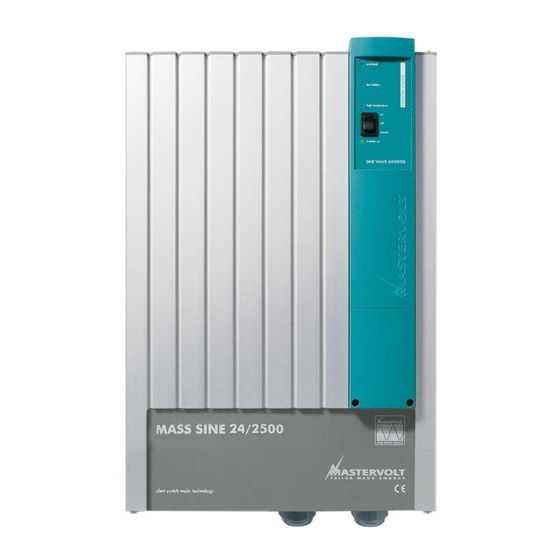
Mass SINE 12/2000, 24/2500 & 48/2500 - 230V / 50Hz Mass SINE 12/2000 & 24/2500 - 117V / 60Hz MASTERVOLT Snijdersbergweg 93, 1105 AN Amsterdam The Netherlands Tel.: +31-20-3422100 V3.
Page 2
CONTENTS GENERAL INFORMATION ............. .24 Use of this manual .
• possible errors in the manuals and the results thereof. GUARANTEE SPECIFICATIONS Mastervolt guarantees that this unit has been built CAREFUL ! according to the legally applicable standards and Never remove the type specifications. Should work take place, which is not number plate.
Mastervolt is not liable for any damage resul- ting from failure to comply with the above. 3 Check the wiring at least once a year. Defects such as loose connections, heat damaged cables etc.
In addition such manufactu- rer must agree to indemnify Mastervolt from any claims arising from the use of Mastervolt parts in the life support equipment. November 2000 / Mass Sine 12/1200, 12/2000, 24/1500, 24/2500 & 48/2500/ EN...
INSTALLATION INSTALLATION During installation and commissioning of Never remove the type number plate! the MASS inverter, the Safety Guidelines Important technical data required for servi- and Measures are applicable at all times. ce, maintenance and later delivery of parts See chapter 2 of this manual. can be obtained from the type number plate (see fig.
INSTALLATION MOUNTING OF THE CABINET To mount the MASS inverter follow the described instructions: 3 Mount the MASS inverter with four screws or 1 Determine the mounting points (see fig. 2 and 3). bolts (M6) to the wall. 2 Drill mounting holes for the cabinet. 4 Fasten all screws or bolts securely.
INSTALLATION CONNECTING The Mastervolt Service Centers have all accessories Connect the AC on-board system brown phase 1.5- available, e.g. battery terminals and supply cables in 2.5 mm wire to terminal L1, the blue 0-phase wire to all sizes. terminal N and the green/yellow earth wire to Before beginning to connect the wiring, terminal PE (see fig.
Use DC cables of the correct size. INVERTER, THE AC GENSET AND/OR SHORE POWER CONNECTING THE REMOTE CONTROL Please contact your Mastervolt supplier if you intend PANEL to use the inverter with a genset or shore power connection. Handswitched or simple relay switching...
Page 11
INSTALLATION Fig. 4: Connection of the Mass Sine. C4-RI, remote control panel. Inverter Control failure Fig. 5: Connection cable for panel C4-RI (not delivered as a standard). EN / Mass Sine 12/1200, 12/2000, 24/1500, 24/2500 & 48/2500 / June 2000...
OPERATION ON THE REMOTE CONTROL Remove the short circuit and reset the inverter by If you use a remote control panel, put the on/off switching it off and on. switch to ‘remote’, and put the on/off switch on the re- mote control panel to ‘on’.
MAINTENANCE MAINTENANCE For a reliable and optimum function of the inverter, the following is required: • Check at least once a year if all cable and wire connections are still firmly connected. • Keep the inverter dry, clean and dust-free, in order to ensure good heat discharge.
If you cannot correct a problem with the aid of the malfunction table, contact your Mastervolt Service Center or Mastervolt Amsterdam for an extended service list, tel: INT+ 31-20-3422100. EN / Mass Sine 12/1200, 12/2000, 24/1500, 24/2500 & 48/2500 / June 2000...
TECHNICAL DATA TECHNICAL DATA 230V INVERTERS GENERAL Function apparatus supplying of AC equipment Models Mass Sine 12/1200, 24/1500, 12/2000, 24/2500 and 48/2500 Manufacturer Mastervolt, Amsterdam INPUT 12/1200 12/1200 24/1500 12/2000 24/2500 48/2500 Battery voltage nominal 12 Volt 24 Volt 12 Volt...
Page 17
TECHNICAL DATA TECHNICAL DATA 117V INVERTERS GENERAL Function apparatus supplying of AC equipment Models Mass Sine 12/1000, 24/1000, 12/2000 and 24/2500 Manufacturer Mastervolt, Amsterdam INPUT 12/1000 12/1000 24/1000 12/2000 24/2500 Battery voltage nominal 12 Volt 24 Volt 12 Volt 24 Volt...
ENERGY SAVING MODES ENERGY SAVING MODES LOW ENERGY MODE For applications that require a very low energy mo- de, it is possible to set the inverter into “low energy mode”. The “low energy mode” can be selected by placing a jumper (black) on the two metal pins on the bottom left of the unit (see fig.
Product: MASS sine wave inverters Models: Mass Sine 12/1200-230V Mass Sine 12/1000-117V Mass Sine 24/1500-230V Mass Sine 24/1000-117V Mass Sine 12/2000-230V Mass Sine 12/2000-117V Mass Sine 24/2500-230V Mass Sine 24/2500-117V Mass Sine 48/2500-230V Conform with the provision of the EC: EMC directive 89/336/EEC and amendments 92/31/EEC, 93/68/EEC.
Page 20
MASTERVOLT Snijdersbergweg 93, 1105 AN Amsterdam, The Netherlands Tel.: INT+ 31-20-3422100 Fax: INT+ 31-20-6971006...