Table of Contents
Advertisement
USER'S AND INSTALLATION MANUAL / GEBRUIKERS- EN INSTALLATIEHANDLEIDING
BEDIENUNGS- UND INSTALLATIONSANLEITUNG / MANUEL UTILISATEURS ET D'INSTALLATION
MANUAL DEL USUARIO Y DE INSTALACIÓN / MANUALE DI USO E MANUTENZIONE
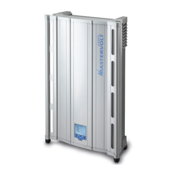
CS15TL / CS20TL
High power grid connected solar inverter
MASTERVOLT
Snijdersbergweg 93,
1105 AN Amsterdam
The Netherlands
Tel.: +31-20-3422100
Fax.: +31-20-6971006
www.mastervolt.com
Sunmaster
ENGLISH:
NEDERLANDS:
DEUTSCH:
FRANÇAIS:
CASTELLANO:
ITALIANO:
Copyright © 2010 Mastervolt, v 1.4 August 2010
PAGE 1
PAGINA 37
SEITE 73
PAGINA 109
PÁGINA 145
PÁGINA 181
Advertisement
Table of Contents


Need help?
Do you have a question about the Sunmaster CS15TL and is the answer not in the manual?
Questions and answers
How many 370w 45v solar panel will I use to install the. CT15TL